2003 JEEP GRAND CHEROKEE spec
[x] Cancel search: specPage 1482 of 2199

(8) Start engine and let idle long enough to circu-
late power steering fluid through flow/pressure test
gauge.
(9) Shut off the engine and check the fluid level,
add fluid as necessary. Start engine again and let
idle.
(10) The initial pressure reading should be
345-552 kPa (50-80 psi). If pressure is higher inspect
the hoses for restrictions and repair as necessary.
(11) Increase the engine speed to 1500 RPM and
read the flow meter. The reading should be 2.4 - 2.8
GPM, if the reading is below this specification the
pump should be replaced.
CAUTION: This next step involves testing maximum
pump pressure output and flow control valve oper-
ation. Do not leave valve closed for more than three
seconds as the pump could be damaged.
(12) Close valve fully three times for three seconds
and record highest pressure indicated each time.All
three readings must be at pump relief pressure
specifications and within 345 kPa (50 psi) of
each other.
²Pressures above specifications but not within
345 kPa (50 psi) of each other, replace pump.
²Pressures within 345 kPa (50 psi) of each other
but below specifications, replace pump.
CAUTION: Do not force the pump to operate against
the stops for more than 2 to 4 seconds at a time
because, pump damage will result.
(13) Open the test valve and turn the steering
wheel to the extreme left and right positions against
the stops. Record the highest pressure reading at
each position. Compare readings to the pump specifi-
cations chart. If pressures readings are not within 50
psi. of each other, the gear is leaking internally and
must be repaired.
GEAR INLET SPECIFICATIONS 4.0L & 4.7L
ENGINERELIEF
PRESSURE 50FLOW RATE
(GPM)
4.0L 9653 kPa (1400 psi)
1500 RPM 2.4 - 2.8
GPM
4.7L 9653 kPa (1450 psi)
PUMP MOTOR SPECIFICATIONS 4.7L
ENGINERELIEF
PRESSURE 50FLOW RATE
(GPM)
4.7L 9653 kPa (1900 psi)1100 RPM 2.4-2.8
GPM Minium
@ 200 psi
DIAGNOSIS AND TESTING - 4.7L -
HYDRAULIC
The following procedures are used to test the oper-
ation of the power steering and hydraulic fan sys-
tems on the vehicle. This test will provide the gallons
per minute (GPM) or flow rate of the power steering
pump along with any maximum relief pressure. Per-
form test anytime a power steering system problem
is present. This test will determine if the power
steering pump, hydraulic fan, and power steering
gear are not functioning properly. It will also deter-
mine if the flow coming out of the hydraulic fan
motor is sufficient for the power steering gear. The
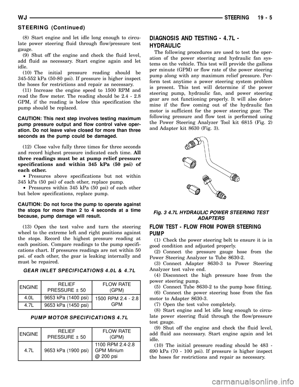
following pressure and flow test is performed using
the Power Steering Analyzer Tool kit 6815 (Fig. 2)
and Adapter kit 8630 (Fig. 3).
FLOW TEST - FLOW FROM POWER STEERING
PUMP
(1) Check the power steering belt to ensure it is in
good condition and adjusted properly.
(2) Connect the pressure gauge hose from the
Power Steering Analyzer to Tube 8630-2.
(3) Connect Adapter 8630-3 to Power Steering
Analyzer test valve end.
(4) Disconnect the high pressure hose from the
power steering pump.
(5) Connect Tube 8630-2 to the pump hose fitting.
(6) Connect the power steering hose from the fan
motor to Adapter 8630-3.
(7) Open the test valve completely.
(8) Start engine and let idle long enough to circu-
late power steering fluid through the flow/pressure
test gauge.
(9) Shut off the engine and check the fluid level,
add fluid ass necessary. Start engine again and let
idle.
(10) The initial pressure reading should be 483 -
690 kPa (70 - 100 psi). If pressure is higher inspect
the hoses for restrictions and repair as necessary.
Fig. 3 4.7L HYDRAULIC POWER STEERING TEST
ADAPTERS
WJSTEERING 19 - 5
STEERING (Continued)
Page 1483 of 2199

(11) Increase the engine speed to 1100 rpm and
read the flow meter. The reading should be 2.6 GPM
minimum, if the reading is below this specification,
the pump should be replaced.
FLOW AND PRESSURE TEST - FLOW FROM
HYDRAULIC FAN MOTOR TO STEERING GEAR
(should be done if necessary after the Pump flow
test)
(1) Connect the pressure gauge hose from the
Power Steering Analyzer to Fitting 8630-1.
(2) Connect Adapter 8630-4 to Power Steering
Analyzer test valve end.
(3) Disconnect the high pressure hose from the
power steering gear.
(4) Connect Fitting 8630-1 to the high pressure
hose.
(5) Connect Adapter 8630-4 to the power steering
gear.
(6) Open the test valve completely.
(7) Start engine and let idle long enough to circu-
late power steering fluid through the flow/pressure
test gauge.
(8) Shut off the engine and check the fluid level,
add fluid ass necessary. Start engine again and let
idle.
(9) The initial pressure reading should be 345-552
kPa (50-80 psi). If pressure is higher inspect the
hoses for restrictions and repair as necessary.(10) Increase the engine speed to 1500 RPM and
read the flow meter. The reading should be 2.4 - 2.8
GPM if the reading is below this specification the fan
should be replaced.
CAUTION: This next step involves testing maximum
fan motor steering relief pressure. Do not leave the
valve closed for more than three seconds.
(11) Close the valve fully three times for three sec-
onds and record highest pressures indicated each
time. All three readings must be at fan motor steer-
ing relief pressures.
(12) Open the test valve and turn the steering
wheel to the extreme left and right positions against
the stops. Record the highest pressure readings at
each position. If pressure readings are not within 50
psi from each other, the gear is leaking internally
and must be repaired.
PUMP MOTOR SPECIFICATIONS 4.7L
ENGINERELIEF
PRESSURE 50FLOW RATE
(GPM)
4.7L 9653 kPa (1900 psi)1100 RPM 2.4-2.8
GPM Minium
@ 200 psi
19 - 6 STEERINGWJ
STEERING (Continued)
Page 1484 of 2199

COLUMN
TABLE OF CONTENTS
page page
COLUMN
DESCRIPTION
SERVICE WARNINGS AND CAUTIONS......7
REMOVAL.............................8
INSTALLATION.........................11
SPECIFICATIONS
TORQUE CHART......................12
SPECIAL TOOLS
STEERING COLUMN...................12
IGNITION SWITCH
DESCRIPTION.........................12
DIAGNOSIS AND TESTING - IGNITION
SWITCH............................12
REMOVAL
IGNITION SWITCH REMOVAL............13INSTALLATION
IGNITION SWITCH INSTALLATION........13
KEY-IN IGNITION SWITCH
DESCRIPTION.........................14
OPERATION...........................14
DIAGNOSIS AND TESTING
KEY-IN IGNITION SWITCH..............14
LOCK CYLINDER
REMOVAL.............................14
INSTALLATION.........................15
STEERING WHEEL
REMOVAL.............................15
INSTALLATION.........................15
COLUMN
DESCRIPTION
SERVICE WARNINGS AND CAUTIONS
DESCRIPTION
The tilt column (Fig. 1) has been designed to be
serviced as an assembly, less the wiring, switches,
shrouds, steering wheel, etc. Most steering column
components can be serviced without removing the
steering column from the vehicle.To service the steering wheel, switches or air-
bag,(Refer to 8 - ELECTRICAL/RESTRAINTS -
WARNING).
WARNING: THE AIRBAG SYSTEM IS A SENSITIVE,
COMPLEX ELECTRO-MECHANICAL UNIT. BEFORE
ATTEMPTING TO DIAGNOSE, REMOVE OR INSTALL
THE AIRBAG SYSTEM COMPONENTS YOU MUST
FIRST DISCONNECT AND ISOLATE THE BATTERY
NEGATIVE (GROUND) CABLE. THEN WAIT TWO
MINUTES FOR THE SYSTEM CAPACITOR TO DIS-
CHARGE. FAILURE TO DO SO COULD RESULT IN
ACCIDENTAL DEPLOYMENT OF THE AIRBAG AND
POSSIBLE PERSONAL INJURY. THE FASTENERS,
SCREWS, AND BOLTS, ORIGINALLY USED FOR
THE AIRBAG COMPONENTS, HAVE SPECIAL COAT-
INGS AND ARE SPECIFICALLY DESIGNED FOR THE
AIRBAG SYSTEM. THEY MUST NEVER BE
REPLACED WITH ANY SUBSTITUTES. ANYTIME A
NEW FASTENER IS NEEDED, REPLACE WITH THE
CORRECT FASTENERS PROVIDED IN THE SERVICE
PACKAGE OR FASTENERS LISTED IN THE PARTS
BOOKS.
CAUTION: Safety goggles should be worn at all
times when working on steering columns.
Fig. 1 Steering Column
WJCOLUMN 19 - 7
Page 1489 of 2199

SPECIFICATIONS
TORQUE CHART
TORQUE SPECIFICATIONS
DESCRIPTION N´m Ft. Lbs. In. Lbs.
Steering Column
Steering Wheel Nut61 45 Ð
Steering Column
Column Bracket Nuts12 Ð 105
Steering Column
Shaft Coupler Bolts49 36 Ð
SPECIAL TOOLS
STEERING COLUMN
IGNITION SWITCH
DESCRIPTION
The electrical ignition switch is located on the
steering column. It is used as the main on/off switch-
ing device for most electrical components. The
mechanical key lock cylinder is used to engage/disen-
gage the electrical ignition switch.
DIAGNOSIS AND TESTING - IGNITION SWITCH
ELECTRICAL DIAGNOSIS
For ignition switch electrical schematics, refer to
Ignition Switch in Wiring Diagrams.
MECHANICAL DIAGNOSIS (KEY DIFFICULT TO
ROTATE)
Vehicles equipped with an automatic trans-
mission and a floor mounted shifter:a cable is
used to connect the interlock device in the steering
column assembly, to the transmission floor shift
lever. This interlock device is used to lock the trans-
mission shifter in the PARK position when the key
lock cylinder is rotated to the LOCKED or ACCES-
SORY position. The interlock device within the steer-
ing column is not serviceable. If repair is necessary,the steering column assembly must be replaced,(Re-
fer to 19 - STEERING/COLUMN - REMOVAL).
If the ignition key is difficult to rotate to or from
the LOCK or ACCESSORY position, it may not be
the fault of the key cylinder or the steering column
components. The brake transmission shift interlock
cable may be out of adjustment,(Refer to 21 -
TRANSMISSION/TRANSAXLE/AUTOMATIC -
44RE/SHIFT INTERLOCK MECHANISM - ADJUST-
MENTS) .
Vehicles equipped with an automatic trans-
mission and a steering column mounted shifter:
an interlock device is located within the steering col-
umn. This interlock device is used to lock the trans-
mission shifter in the PARK position when the key
lock cylinder is in the LOCKED or ACCESSORY
position. If it is difficult to rotate the key to or from
the LOCK or ACCESSORY position, the interlock
device within the steering column may be defective.
This device is not serviceable. If repair is necessary,
the steering column assembly must be replaced,(Re-
fer to 19 - STEERING/COLUMN - REMOVAL).
Vehicles equipped with a manual transmis-
sion and a floor mounted shifter:on certain mod-
els, a lever is located on the steering column behind
the ignition key lock cylinder. The lever must be
manually operated to allow rotation of the ignition
key lock cylinder to the LOCK or ACCESSORY posi-
tion. If it is difficult to rotate the key to the LOCK or
ACCESSORY position, the lever mechanism may be
defective. This mechanism is not serviceable. If
repair is necessary, the steering column assembly
must be replaced,(Refer to 19 - STEERING/COL-
UMN - REMOVAL).
On other models, the ignition key cylinder must be
depressed to allow it to be rotated into the LOCK or
ACCESSORY position. If it is difficult to rotate the
key to the LOCK or ACCESSORY position, the lock
mechanism within the steering column may be defec-
tive. This mechanism is not serviceable. If repair is
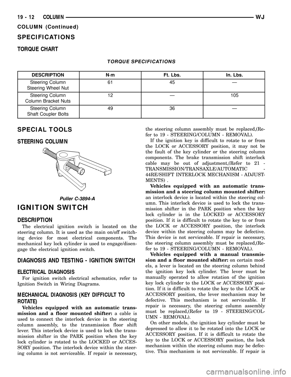
Puller C-3894-A
19 - 12 COLUMNWJ
COLUMN (Continued)
Page 1493 of 2199

GEAR
TABLE OF CONTENTS
page page
GEAR
DESCRIPTION.........................16
OPERATION...........................16
REMOVAL.............................16
INSTALLATION.........................16
ADJUSTMENTS
STEERING GEAR.....................18
SPECIFICATIONS
POWER STEERING GEAR..............18
SPECIAL TOOLS
POWER STEERING GEAR..............19
PITMAN SHAFT
REMOVAL.............................20INSTALLATION.........................20
PITMAN SHAFT BEARING
REMOVAL.............................22
INSTALLATION.........................22
PITMAN SHAFT SEAL
REMOVAL.............................22
INSTALLATION.........................23
RACK PISTON/VALVE ASSEMBLY
REMOVAL.............................23
INSTALLATION.........................25
STUB SHAFT HOUSING
REMOVAL.............................25
INSTALLATION.........................25
GEAR
DESCRIPTION
The power steering gear is a recirculating ball type
gear (Fig. 1) .
The following gear components can be serviced:
²Pitman Shaft and Cover
²Pitman Shaft Bearings
²Pitman Shaft Oil Seal/Dust Seal
²Stud Shaft Housing with Seal
²O-Rings and Teflon Rings
NOTE: If rack piston assembly is damaged the gear
must be replaced.
OPERATION
The gear acts as a rolling thread between the
worm shaft and rack piston. The worm shaft is sup-
ported by a thrust bearing at the lower end and a
bearing assembly at the upper end. When the worm
shaft is turned the rack piston moves. The rack pis-
ton teeth mesh with the pitman shaft. Turning the
worm shaft turns the pitman shaft, which turns the
steering linkage.
REMOVAL
(1) Place the front wheels in the straight ahead
position with the steering wheel centered and locked.
(2) Remove the air cleaner housing,(Refer to 9 -
ENGINE/AIR INTAKE SYSTEM/AIR CLEANER
HOUSING - REMOVAL).
(3) Drain or siphon the power steering system.(4) Remove the pressure and return lines (Fig.
2)from the steering gear. Refer to hose removal in
this section.
(5) Remove the column coupler shaft bolt (Fig.
2)and remove the shaft from the gear.
(6) Raise and support the vehicle.
(7) Remove the left front wheel and tire assembly.
(8) Remove the pitman arm from gear with Puller
C-4150A.
(9) Remove the windshield washer reservoir,(Refer
to 8 - ELECTRICAL/WIPERS/WASHERS/WASHER
RESERVOIR - REMOVAL).
(10) Remove the steering gear mounting bolts.
Remove the steering gear out of the engine compart-
ment (Fig. 3).
INSTALLATION
(1) Position the steering gear on the frame rail and
install the bolts. Tighten the bolts to 108 N´m (80 ft.
lbs.) torque.
(2) Install the pitman arm and tighten nut to 251
N´m (185 ft. lbs.).
(3) Install windshield washer reservoir,(Refer to 8 -
ELECTRICAL/WIPERS/WASHERS/WASHER RES-
ERVOIR - INSTALLATION).
(4) Install the wheel and tire assembly.
(5) Remove the support and lower the vehicle.
(6) Install the pressure and return hoses to the
steering gear and tighten to 20-38 N´m (14-28 ft.
lbs.).
(7) Install the column coupler shaft.
(8) Install the air cleaner housing,(Refer to 9 -
ENGINE/AIR INTAKE SYSTEM/AIR CLEANER
HOUSING - INSTALLATION).
19 - 16 GEARWJ
Page 1495 of 2199

ADJUSTMENTS
STEERING GEAR
NOTE: Adjusting the steering gear in the vehicle is
not recommended. Remove gear from the vehicle
and drain the fluid. Then mount gear in a vise to
perform adjustments.
OVER-CENTER
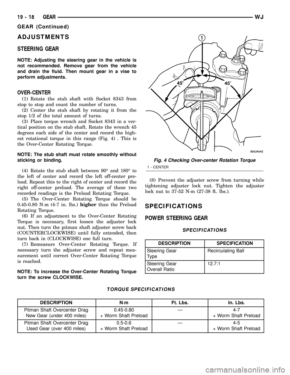
(1) Rotate the stub shaft with Socket 8343 from
stop to stop and count the number of turns.
(2) Center the stub shaft by rotating it from the
stop 1/2 of the total amount of turns.
(3) Place torque wrench and Socket 8343 in a ver-
tical position on the stub shaft. Rotate the wrench 45
degrees each side of the center and record the high-
est rotational torque in this range (Fig. 4) . This is
the Over-Center Rotating Torque.
NOTE: The stub shaft must rotate smoothly without
sticking or binding.
(4) Rotate the stub shaft between 90É and 180É to
the left of center and record the left off-center pre-
load. Repeat this to the right of center and record the
right off-center preload. The average of these two
recorded readings is the Preload Rotating Torque.
(5) The Over-Center Rotating Torque should be
0.45-0.80 N´m (4-7 in. lbs.)higherthan the Preload
Rotating Torque.
(6) If an adjustment to the Over-Center Rotating
Torque is necessary, first loosen the adjuster lock
nut. Then turn the pitman shaft adjuster screw back
(COUNTERCLOCKWISE) until fully extended, then
turn back in (CLOCKWISE) one full turn.
(7) Remeasure Over-Center Rotating Torque. If
necessary turn the adjuster screw and repeat mea-
surement until correct Over-Center Rotating Torque
is reached.
NOTE: To increase the Over-Center Rotating Torque
turn the screw CLOCKWISE.(8) Prevent the adjuster screw from turning while
tightening adjuster lock nut. Tighten the adjuster
lock nut to 37-52 N´m (27-38 ft. lbs.).
SPECIFICATIONS
POWER STEERING GEAR
SPECIFICATIONS
DESCRIPTION SPECIFICATION
Steering Gear
TypeRecirculating Ball
Steering Gear
Overall Ratio12.7:1
TORQUE SPECIFICATIONS
DESCRIPTION N´m Ft. Lbs. In. Lbs.
Pitman Shaft Overcenter Drag
New Gear (under 400 miles)0.45-0.80
+ Worm Shaft PreloadÐ 4-7
+ Worm Shaft Preload
Pitman Shaft Overcenter Drag
Used Gear (over 400 miles)0.5-0.6
+ Worm Shaft PreloadÐ 4-5
+ Worm Shaft Preload
Fig. 4 Checking Over-center Rotation Torque
1 - CENTER
19 - 18 GEARWJ
GEAR (Continued)
Page 1496 of 2199

SPECIAL TOOLS
POWER STEERING GEAR
Puller Seal 7794-A
Slide Hammer C-637
Remover, Pitman Arm C-4150A
Handle C-4171
Driver 8277
Driver 8294
Scoket 8343
WJGEAR 19 - 19
GEAR (Continued)
Page 1498 of 2199

(2) Install lower pitman shaft bearing with the
other side Driver 8294 and Handle C-4171 (Fig. 11).
Drive bearing into housing until the bearing shoulder
is seated against the housing.
(3) Coat the oil seal and backup washers withspe-
cial greasesupplied with the new seal.
(4) Install the oil seal with Driver 8294 and Han-
dle C-4171.
(5) Install plastic backup washer.
NOTE: The plastic backup washer has a lip on the
inside diameter that faces down towards the oil
seal.
(6) Install metal backup washer.
(7) Install the retainer ring with snap ring pliers.(8) Coat the dust seal withspecial greasesup-
plied with the new seal.
(9) Install dust seal with Driver 8294 and Handle
C-4171.
(10) Install new pitman shaft cover o-ring.
(11) Install pitman shaft assembly into the hous-
ing.
(12) Install cover bolts and tighten to 62 N´m (46
ft. lbs.).
(13) Perform over-center rotation torque adjust-
ment.
Fig. 8 Oil Seal Retaining Ring
1 - SNAP RING PLIERS
2 - RETAINING RING
Fig. 9 Bearing Driver
1 - UPPER BEARING
2 - LOWER BEARING
3 - DRIVER
Fig. 10 Upper Pitman Shaft Bearing
1 - DRIVER
2 - UPPER BEARING
Fig. 11 Lower Pitman Shaft Bearing
1 - STEERING GEAR
2 - BEARING SHOULDER
3 - DRIVER
4 - LOWER BEARING
WJGEAR 19 - 21
PITMAN SHAFT (Continued)