Page 1888 of 2199
INSTALLATION
(1) Position hinge on ªAº pillar. (Use 3MtFast and
Firm or equivalent on the hinge to body mating sur-
face as a sealant.)
(2) Install hinge to body bolts, but do not tighten.
(3) Align the hinge to the reference marks and
torque the bolts to 35N´m (26 ft. lbs.).
(4) Install the door on the hinge and align with the
reference marks.
(5) Tighten the door to hinge fasteners.
(6) For adjustment see door adjustment procedure.
INSIDE HANDLE ACTUATOR
REMOVAL
(1) Remove door trim panel, refer to (Refer to 23 -
BODY/DOOR - FRONT/TRIM PANEL - REMOVAL).
(2) Disconnect latch and lock rods from inside han-
dle actuator.
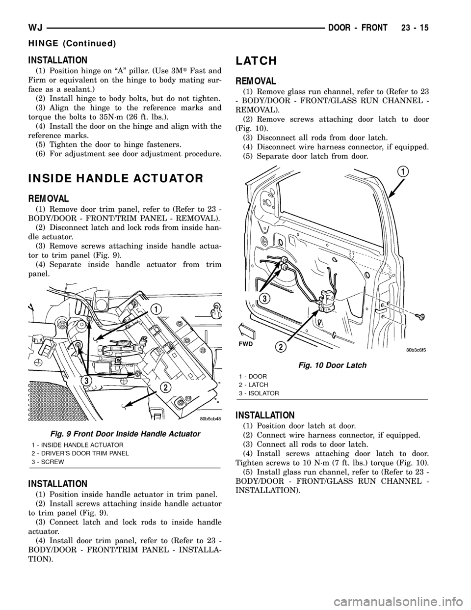
(3) Remove screws attaching inside handle actua-
tor to trim panel (Fig. 9).
(4) Separate inside handle actuator from trim
panel.
INSTALLATION
(1) Position inside handle actuator in trim panel.
(2) Install screws attaching inside handle actuator
to trim panel (Fig. 9).
(3) Connect latch and lock rods to inside handle
actuator.
(4) Install door trim panel, refer to (Refer to 23 -
BODY/DOOR - FRONT/TRIM PANEL - INSTALLA-
TION).
LATCH
REMOVAL
(1) Remove glass run channel, refer to (Refer to 23
- BODY/DOOR - FRONT/GLASS RUN CHANNEL -
REMOVAL).
(2) Remove screws attaching door latch to door
(Fig. 10).
(3) Disconnect all rods from door latch.
(4) Disconnect wire harness connector, if equipped.
(5) Separate door latch from door.
INSTALLATION
(1) Position door latch at door.
(2) Connect wire harness connector, if equipped.
(3) Connect all rods to door latch.
(4) Install screws attaching door latch to door.
Tighten screws to 10 N´m (7 ft. lbs.) torque (Fig. 10).
(5) Install glass run channel, refer to (Refer to 23 -
BODY/DOOR - FRONT/GLASS RUN CHANNEL -
INSTALLATION).
Fig. 9 Front Door Inside Handle Actuator
1 - INSIDE HANDLE ACTUATOR
2 - DRIVER'S DOOR TRIM PANEL
3 - SCREW
Fig. 10 Door Latch
1 - DOOR
2-LATCH
3 - ISOLATOR
WJDOOR - FRONT 23 - 15
HINGE (Continued)
Page 1889 of 2199
ADJUSTMENTS
DOOR LATCH
DOOR LATCH ADJUSTMENT
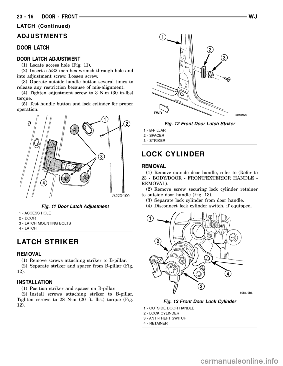
(1) Locate access hole (Fig. 11).
(2) Insert a 5/32-inch hex-wrench through hole and
into adjustment screw. Loosen screw.
(3) Operate outside handle button several times to
release any restriction because of mis-alignment.
(4) Tighten adjustment screw to 3 N´m (30 in-lbs)
torque.
(5) Test handle button and lock cylinder for proper
operation.
LATCH STRIKER
REMOVAL
(1) Remove screws attaching striker to B-pillar.
(2) Separate striker and spacer from B-pillar (Fig.
12).
INSTALLATION
(1) Position striker and spacer on B-pillar.
(2) Install screws attaching striker to B-pillar.
Tighten screws to 28 N´m (20 ft. lbs.) torque (Fig.
12).
LOCK CYLINDER
REMOVAL
(1) Remove outside door handle, refer to (Refer to
23 - BODY/DOOR - FRONT/EXTERIOR HANDLE -
REMOVAL).
(2) Remove screw securing lock cylinder retainer
to outside door handle (Fig. 13).
(3) Separate lock cylinder from door handle.
(4) Disconnect lock cylinder switch, if equipped.
Fig. 11 Door Latch Adjustment
1 - ACCESS HOLE
2 - DOOR
3 - LATCH MOUNTING BOLTS
4-LATCH
Fig. 12 Front Door Latch Striker
1 - B-PILLAR
2 - SPACER
3 - STRIKER
Fig. 13 Front Door Lock Cylinder
1 - OUTSIDE DOOR HANDLE
2 - LOCK CYLINDER
3 - ANTI-THEFT SWITCH
4 - RETAINER
23 - 16 DOOR - FRONTWJ
LATCH (Continued)
Page 1891 of 2199
WINDOW REGULATOR
REMOVAL
(1) Remove front door glass, refer to (Refer to 23 -
BODY/DOOR - FRONT/DOOR GLASS - REMOVAL).
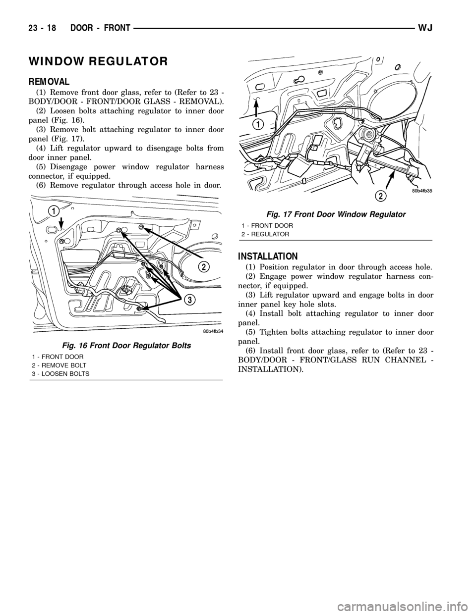
(2) Loosen bolts attaching regulator to inner door
panel (Fig. 16).
(3) Remove bolt attaching regulator to inner door
panel (Fig. 17).
(4) Lift regulator upward to disengage bolts from
door inner panel.
(5) Disengage power window regulator harness
connector, if equipped.
(6) Remove regulator through access hole in door.
INSTALLATION
(1) Position regulator in door through access hole.
(2) Engage power window regulator harness con-
nector, if equipped.
(3) Lift regulator upward and engage bolts in door
inner panel key hole slots.
(4) Install bolt attaching regulator to inner door
panel.
(5) Tighten bolts attaching regulator to inner door
panel.
(6) Install front door glass, refer to (Refer to 23 -
BODY/DOOR - FRONT/GLASS RUN CHANNEL -
INSTALLATION).
Fig. 16 Front Door Regulator Bolts
1 - FRONT DOOR
2 - REMOVE BOLT
3 - LOOSEN BOLTS
Fig. 17 Front Door Window Regulator
1 - FRONT DOOR
2 - REGULATOR
23 - 18 DOOR - FRONTWJ
Page 1894 of 2199
INSTALLATION
(1) Position outside handle in door.
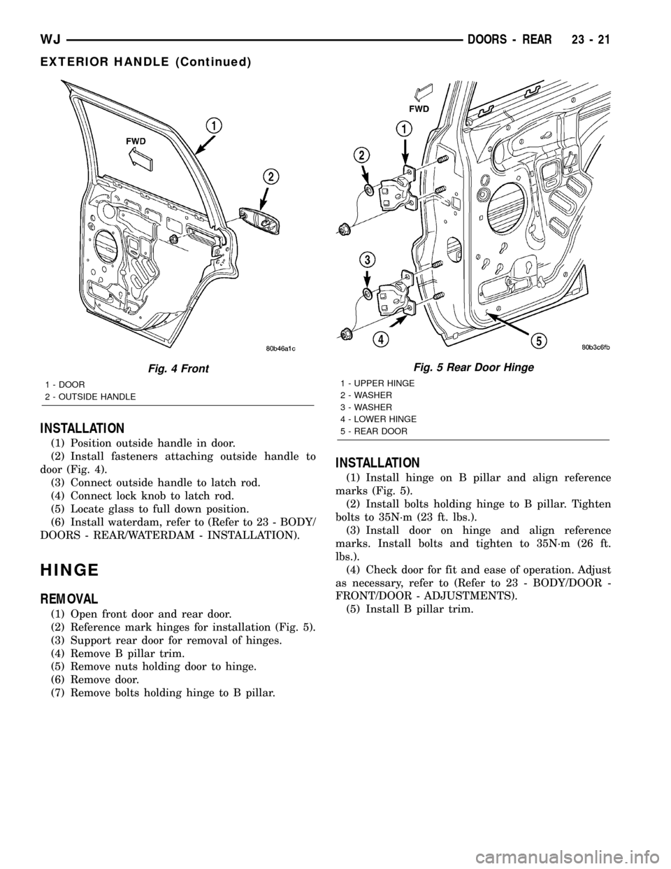
(2) Install fasteners attaching outside handle to
door (Fig. 4).
(3) Connect outside handle to latch rod.
(4) Connect lock knob to latch rod.
(5) Locate glass to full down position.
(6) Install waterdam, refer to (Refer to 23 - BODY/
DOORS - REAR/WATERDAM - INSTALLATION).
HINGE
REMOVAL
(1) Open front door and rear door.
(2) Reference mark hinges for installation (Fig. 5).
(3) Support rear door for removal of hinges.
(4) Remove B pillar trim.
(5) Remove nuts holding door to hinge.
(6) Remove door.
(7) Remove bolts holding hinge to B pillar.
INSTALLATION
(1) Install hinge on B pillar and align reference
marks (Fig. 5).
(2) Install bolts holding hinge to B pillar. Tighten
bolts to 35N´m (23 ft. lbs.).
(3) Install door on hinge and align reference
marks. Install bolts and tighten to 35N´m (26 ft.
lbs.).
(4) Check door for fit and ease of operation. Adjust
as necessary, refer to (Refer to 23 - BODY/DOOR -
FRONT/DOOR - ADJUSTMENTS).
(5) Install B pillar trim.
Fig. 4 Front
1 - DOOR
2 - OUTSIDE HANDLE
Fig. 5 Rear Door Hinge
1 - UPPER HINGE
2 - WASHER
3 - WASHER
4 - LOWER HINGE
5 - REAR DOOR
WJDOORS - REAR 23 - 21
EXTERIOR HANDLE (Continued)
Page 1903 of 2199
(3) Install fascia, refer to (Refer to 13 - FRAMES
& BUMPERS/BUMPERS/FRONT FASCIA - INSTAL-
LATION).
HEADLAMP MOUNTING
MODULE
REMOVAL
CAUTION: Take special care when handling the
HMM not to damage the upper mounting tabs. Step
#3 must be performed prior to removing HMM from
the vehicle to prevent damage to HMM.
(1) Remove fascia, refer to (Refer to 13 - FRAMES
& BUMPERS/BUMPERS/FRONT FASCIA - REMOV-
AL).
(2) Remove inner fender liner.
(3) Reach into the wheelhouse opening and disen-
gage the retainer attaching the HMM to each side of
the body.
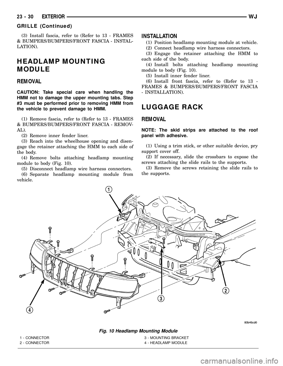
(4) Remove bolts attaching headlamp mounting
module to body (Fig. 10).
(5) Disconnect headlamp wire harness connectors.
(6) Separate headlamp mounting module from
vehicle.
INSTALLATION
(1) Position headlamp mounting module at vehicle.
(2) Connect headlamp wire harness connectors.
(3) Engage the retainer attaching the HMM to
each side of the body.
(4) Install bolts attaching headlamp mounting
module to body (Fig. 10).
(5) Install inner fender liner.
(6) Install front fascia, refer to (Refer to 13 -
FRAMES & BUMPERS/BUMPERS/FRONT FASCIA
- INSTALLATION).
LUGGAGE RACK
REMOVAL
NOTE: The skid strips are attached to the roof
panel with adhesive.
(1) Using a trim stick, or other suitable device, pry
support cover off.
(2) If necessary, slide the crossbars to expose the
screws attaching the slide rails to the supports.
(3) Remove the screws retaining the slide rails to
the supports.
Fig. 10 Headlamp Mounting Module
1 - CONNECTOR
2 - CONNECTOR3 - MOUNTING BRACKET
4 - HEADLAMP MODULE
23 - 30 EXTERIORWJ
GRILLE (Continued)
Page 1905 of 2199
ROCK RAIL
REMOVAL
(1) Remove the bolts and remove the rock rail.
(Fig. 12)
INSTALLATION
NOTE: Shims may be used to adjust rock rail posi-
tioning, if required.
(1) Loosen the rear bracket slide bolts. (Fig. 13)
(2) Install the rock rail and install the bolts.
(3) Tighten the front bolts to 27 N´m (20 ft. lbs.).
(4) Slide the rear bracket to contact the mounting
surface and tighten the rear mounting bolts to 27
N´m (20 ft. lbs.).
(5) Tighten the slide bolts to 27 N´m (20 ft. lbs.).
(6) Loosen the end cap bolts and slide the end caps
against the body.
(7) Tighten the end cap bolts.
Fig. 12 ROCK RAIL
1 - ROCK RAIL
2 - J-NUTS (3)
3 - J-NUTS (3)
4 - BOLTS (3)
5 - BOLTS (3)
Fig. 13 REAR ROCK RAIL BRACKET
1 - REAR BRACKET
2 - ROCK RAIL
3 - REAR BRACKET BOLTS (2)
4 - END CAP BOLTS (2 PER CAP)
5 - END CAP (2)
23 - 32 EXTERIORWJ
Page 1906 of 2199
HOOD
TABLE OF CONTENTS
page page
GAS PROP
REMOVAL.............................33
INSTALLATION.........................33
HINGE
REMOVAL.............................33
INSTALLATION.........................33
HOOD
REMOVAL.............................33
INSTALLATION.........................34
ADJUSTMENTS
HOOD ADJUSTMENT..................34INSULATION
REMOVAL.............................34
INSTALLATION.........................34
LATCH
REMOVAL.............................34
INSTALLATION.........................34
LATCH RELEASE CABLE
REMOVAL.............................35
INSTALLATION.........................35
GAS PROP
REMOVAL
(1) Raise and support hood.
(2) Using a small flat blade, pry the retainer
attaching hood support prop to lower ball stud.
(3) Slide retainer attaching hood support prop
upper ball stud downward.
(4) Disconnect hood support prop from lower ball
stud and rotate support prop upward and disconnect
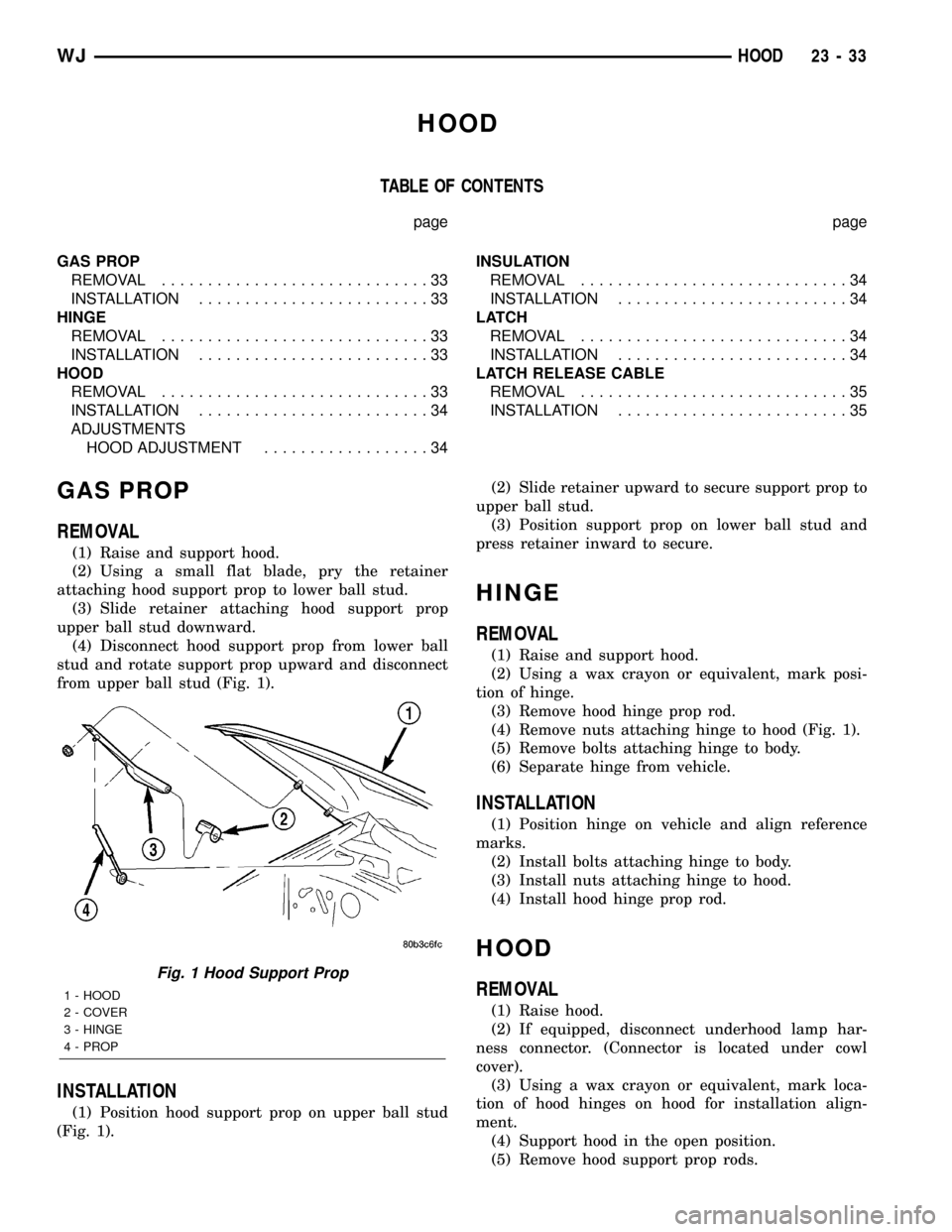
from upper ball stud (Fig. 1).
INSTALLATION
(1) Position hood support prop on upper ball stud
(Fig. 1).(2) Slide retainer upward to secure support prop to
upper ball stud.
(3) Position support prop on lower ball stud and
press retainer inward to secure.
HINGE
REMOVAL
(1) Raise and support hood.
(2) Using a wax crayon or equivalent, mark posi-
tion of hinge.
(3) Remove hood hinge prop rod.
(4) Remove nuts attaching hinge to hood (Fig. 1).
(5) Remove bolts attaching hinge to body.
(6) Separate hinge from vehicle.
INSTALLATION
(1) Position hinge on vehicle and align reference
marks.
(2) Install bolts attaching hinge to body.
(3) Install nuts attaching hinge to hood.
(4) Install hood hinge prop rod.
HOOD
REMOVAL
(1) Raise hood.
(2) If equipped, disconnect underhood lamp har-
ness connector. (Connector is located under cowl
cover).
(3) Using a wax crayon or equivalent, mark loca-
tion of hood hinges on hood for installation align-
ment.
(4) Support hood in the open position.
(5) Remove hood support prop rods.
Fig. 1 Hood Support Prop
1 - HOOD
2 - COVER
3 - HINGE
4 - PROP
WJHOOD 23 - 33
Page 1907 of 2199
(6) Remove bolts attaching hinges to hood.
(7) With the aid of a helper, remove hood from
vehicle.
INSTALLATION
(1) Position hood on hinges.
(2) Install bolts finger-tight.
(3) Align hinges with installation reference marks
and tighten bolts.
(4) Install hood support prop rods.
(5) Connect underhood lamp connector.
(6) Inspect hood for proper alignment and adjust
as necessary.
ADJUSTMENTS
HOOD ADJUSTMENT
The hood attaching holes are enlarged to aid front,
back and side to side adjustment.
(1) If hood is low in relation to cowl panel, insert
shims between hinge and hood.
(2) Adjust hood bumper in or out to adjust hood-
to-fender height alignment.
(3) Adjust the hood latch as necessary. Tighten the
nuts to 11N´m (8 ft. lbs.).
(4) Align the latch striker so that striker enters
the latch squarely and without binding.
INSULATION
REMOVAL
(1) Raise the hood.
(2) Remove the insulation panel fasteners.
(3) Remove the hood insulation panel.
INSTALLATION
(1) Position the insulation panel on the underside
of the hood.
(2) Install the insulation panel fasteners.
(3) Close the hood.
LATCH
REMOVAL
(1) Remove nuts attaching latch to radiator cross-
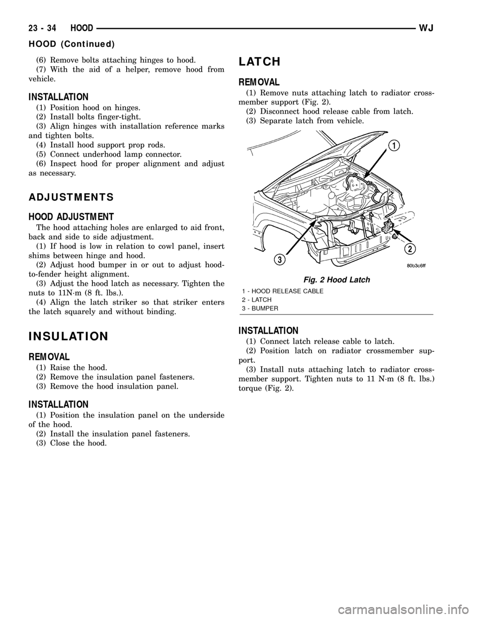
member support (Fig. 2).
(2) Disconnect hood release cable from latch.
(3) Separate latch from vehicle.
INSTALLATION
(1) Connect latch release cable to latch.
(2) Position latch on radiator crossmember sup-
port.
(3) Install nuts attaching latch to radiator cross-
member support. Tighten nuts to 11 N´m (8 ft. lbs.)
torque (Fig. 2).
Fig. 2 Hood Latch
1 - HOOD RELEASE CABLE
2-LATCH
3 - BUMPER
23 - 34 HOODWJ
HOOD (Continued)