Page 1837 of 2199
REAR RETAINER AND OIL PUMP
(1) Remove rear retainer bolts (Fig. 6).
(2) Remove rear bearing locating ring access plug
(Fig. 7).(3) Loosen rear retainer with pry tool to break
sealer bead. Pry only against retainer boss as shown
(Fig. 8).
(4) Remove rear retainer as follows:
(a) Spread rear bearing locating ring with snap
ring pliers (Fig. 9).
(b) Then slide retainer off mainshaft and rear
bearing (Fig. 10).
Fig. 5 Transfer Case Mounting
1 - NV247 TRANSFER CASE
Fig. 6 Rear Retainer Bolt Removal
1 - REAR RETAINER
Fig. 7 Remove Rubber Access Plug
1 - PLUG
Fig. 8 Loosening Rear Retainer
1 - RETAINER BOSS
2-PRYTOOL
3 - SEALER BEAD
4 - REAR RETAINER
21 - 318 TRANSFER CASE - NV247WJ
TRANSFER CASE - NV247 (Continued)
Page 1839 of 2199
REAR CASE
(1) Support transfer case so rear case is facing
upward.
(2) Remove bolts holding front case to rear case.
The case alignment bolt require flat washers (Fig.
13).
(3) Loosen rear case with flat blade screwdriver to
break sealer bead. Insert screwdriver blade only into
notches provided at each end of case (Fig. 14).
(4) Remove rear case (Fig. 15).
PROGRESSIVE COUPLING
(1) Remove oil pump locating snap-ring and pro-
gressive coupling thrust washer from the mainshaft
(Fig. 16).
(2) Remove progressive coupling from mainshaft
(Fig. 16).
Fig. 13 Rear Case Alignment Bolt Locations
1 - ALIGNMENT BOLT AND WASHER (AT EACH END OF CASE)
Fig. 14 Loosening Rear Case
1 - REAR CASE
2 - PRY TOOL (IN CASE SLOT)
3 - FRONT CASE
Fig. 15 Rear Case Removal
1 - REAR HOUSING
2 - MAINSHAFT
3 - TRANSFER CASE
Fig. 16 Progressive Coupling Removal
1 - SNAP-RING
2 - PROGRESSIVE COUPLING
21 - 320 TRANSFER CASE - NV247WJ
TRANSFER CASE - NV247 (Continued)
Page 1841 of 2199

(7) Remove range clutch sleeve, blockout spring,
locking clutch, and locking clutch spring from main-
shaft (Fig. 20).
(8) Remove shift sector. Rotate and tilt sector as
needed to remove it (Fig. 21).
(9) Remove shift sector bushing and O-ring (Fig.
22).
INPUT GEAR/LOW RANGE ASSEMBLY
(1) Turn front case on side so front bearing
retainer is accessible.
(2) Remove front bearing retainer bolts (Fig. 23).
(3) Remove front bearing retainer as follows:(a) Loosen retainer with flat blade screwdriver
to break sealer bead.To avoid damaging case
and retainer, position screwdriver blade only
in slots provided in retainer (Fig. 24).
(b) Then remove retainer from case and gear.
Fig. 20 Range Clutch Sleeve, Blockout Spring,
Locking Clutch and Spring
1 - LOCKING CLUTCH SPRING
2 - BLOCKOUT SPRING
3 - SNAP-RING
4 - RANGE CLUTCH SLEEVE
5 - LOCKING CLUTCH
6 - DRIVE SPROCKET HUB
Fig. 21 Shift Sector Removal
1 - SHIFT SECTOR
Fig. 22 Sector Bushing And O-Ring Removal
1 - SHIFT SECTOR BUSHING
2 - O-RING
Fig. 23 Front Bearing Retainer Bolt Removal
1 - FRONT BEARING RETAINER
21 - 322 TRANSFER CASE - NV247WJ
TRANSFER CASE - NV247 (Continued)
Page 1849 of 2199

(7) Install snap-ring to hold input/low range gear
into front bearing (Fig. 47).
(8) Clean gasket sealer residue from retainer and
inspect retainer for cracks or other damage.
(9) Applya3mm(1/8 in.) bead of Mopartgasket
maker or silicone adhesive to sealing surface of
retainer.
(10) Align cavity in seal retainer with fluid return
hole in front of case.
CAUTION: Do not block fluid return cavity on seal-
ing surface of retainer when applying MoparTgas-
ket maker or silicone adhesive sealer. Seal failure
and fluid leak can result.
(11) Install bolts to hold retainer to transfer case
(Fig. 48). Tighten to 21 N´m (16 ft. lbs.) of torque.SHIFT FORKS AND MAINSHAFT
(1) Install new sector shaft O-ring and bushing
(Fig. 49).
(2) Install shift sector (Fig. 50).
(3) Install locking clutch spring, locking clutch,
blockout spring, and range clutch sleeve, to main-
shaft as shown in (Fig. 51). Install snap ring.
(4) Install drive sprocket hub to mainshaft and
manually load the needle bearings.
(5) Install new pads on range fork, if necessary.
Fig. 47 Install Input Gear Snap-Ring
1 - INPUT GEAR
2 - SNAP-RING
Fig. 48 Install Front Bearing Retainer
1 - FRONT BEARING RETAINER
Fig. 49 Sector O-Ring And Bushing Installation
1 - SECTOR BUSHING
2 - O-RING
Fig. 50 Shift Sector Installation
1 - SHIFT SECTOR
21 - 330 TRANSFER CASE - NV247WJ
TRANSFER CASE - NV247 (Continued)
Page 1852 of 2199

(12) Clean sealing flanges of front case and rear
case with a wax and grease remover.
(13) Apply 3 mm (1/8 in.) wide bead of Mopart
gasket maker or silicone adhesive sealer to mounting
flange of front case. Work sealer bead around bolt
holes as shown (Fig. 58).
(14) Align and install rear case on front case (Fig.
59).(15) Verify that oil pickup tube is still seated in
case notch and tube end is pointed toward mainshaft
(Fig. 60).
(16) Install case attaching bolts. Alignment bolts
at each end of case are only ones requiring washers
(Fig. 61).
(17) Tighten case bolts to 27-34 N´m (20-25 ft. lbs.)
torque.
Fig. 58 Applying Sealer To Front Case Flange
1 - FRONT CASE FLANGE
2 - SEALER BEAD
Fig. 59 Rear Case Installation
1 - REAR CASE
2 - FRONT CASE
Fig. 60 Checking Position Of Oil Pickup Tube
1 - TUBE O-RING
2 - CORRECT PICKUP TUBE POSITION
Fig. 61 Alignment Bolt
1 - ALIGNMENT BOLT AND WASHER (AT EACH END OF CASE)
WJTRANSFER CASE - NV247 21 - 333
TRANSFER CASE - NV247 (Continued)
Page 1854 of 2199

(7) Apply 3 mm (1/8 in.) wide bead of Mopartgas-
ket maker or silicone adhesive sealer to mounting
surface of rear retainer. Allow sealer to set-up
slightly before proceeding.
(8) Slide rear retainer onto mainshaft (Fig. 67).
(9) Spread rear bearing locating ring and slide
rear retainer into place on rear case (Fig. 68).
(10) Install and tighten rear retainer bolts to 27-34
N´m (20-25 ft. lbs.).
(11) Install rubber access plug (Fig. 69).
FINAL ASSEMBLY
(1) Install drain plug. Tighten plug to 41-54 N´m
(30-40 ft. lbs.) torque.(2) Level transfer case and fill it with Mopart
Transfer Case Lubricant. Correct fill level is to bot-
tom edge of fill plug hole.
(3) Install and tighten fill plug to 41-54 N´m
(30-40 ft. lbs.) torque.
INSTALLATION
(1) Mount transfer case on a transmission jack.
(2) Secure transfer case to jack with chains.
(3) Position transfer case under vehicle.
(4) Align transfer case and transmission shafts
and install transfer case on transmission.
(5) Install and tighten transfer case attaching nuts
to 35 N´m (26 ft. lbs.) torque (Fig. 70).Fig. 67 Rear Retainer Installation
1 - REAR CASE
2 - REAR RETAINER
Fig. 68 Engaging Rear Bearing Locating Ring
1 - REAR RETAINER
2 - PARALLEL JAW SNAP-RING PLIERS
Fig. 69 Installing Rubber Access Plug
1 - PLUG
Fig. 70 Install Transfer Case
1 - NV247 TRANSFER CASE
WJTRANSFER CASE - NV247 21 - 335
TRANSFER CASE - NV247 (Continued)
Page 1855 of 2199

(6) Connect front propeller shaft and install rear
propeller shaft. (Refer to 3 - DIFFERENTIAL &
DRIVELINE/PROPELLER SHAFT/PROPELLER
SHAFT - INSTALLATION)
(7) Fill transfer case with correct fluid. Check
transmission fluid level. Correct as necessary.
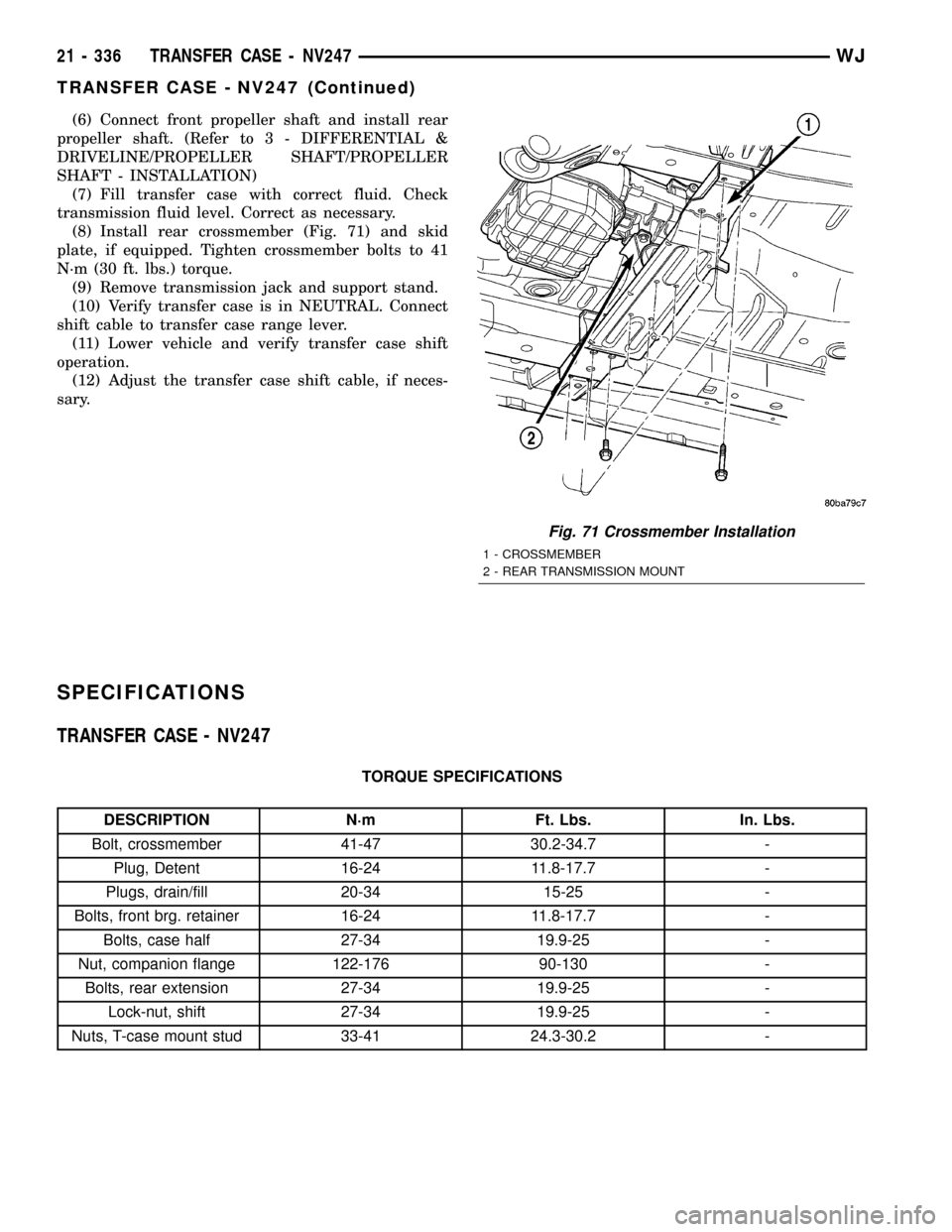
(8) Install rear crossmember (Fig. 71) and skid
plate, if equipped. Tighten crossmember bolts to 41
N´m (30 ft. lbs.) torque.
(9) Remove transmission jack and support stand.
(10) Verify transfer case is in NEUTRAL. Connect
shift cable to transfer case range lever.
(11) Lower vehicle and verify transfer case shift
operation.
(12) Adjust the transfer case shift cable, if neces-
sary.
SPECIFICATIONS
TRANSFER CASE - NV247
TORQUE SPECIFICATIONS
DESCRIPTION N´m Ft. Lbs. In. Lbs.
Bolt, crossmember 41-47 30.2-34.7 -
Plug, Detent 16-24 11.8-17.7 -
Plugs, drain/fill 20-34 15-25 -
Bolts, front brg. retainer 16-24 11.8-17.7 -
Bolts, case half 27-34 19.9-25 -
Nut, companion flange 122-176 90-130 -
Bolts, rear extension 27-34 19.9-25 -
Lock-nut, shift 27-34 19.9-25 -
Nuts, T-case mount stud 33-41 24.3-30.2 -
Fig. 71 Crossmember Installation
1 - CROSSMEMBER
2 - REAR TRANSMISSION MOUNT
21 - 336 TRANSFER CASE - NV247WJ
TRANSFER CASE - NV247 (Continued)
Page 1877 of 2199

SPECIFICATIONS - TORQUE
TORQUE SPECIFICATIONS
DESCRIPTION N´m Ft. Lbs. In. Lbs.
BUCKET SEAT BACK FRAME RECLINER BOLTS TO SEAT CUSHION
FRAME28 20 Ð
BUCKET SEAT RECLINER TO SEAT BACK FRAME BOLTS 28 20 Ð
BUCKET SEAT TRACK ADJUSTER NUTS TO SEAT CUSHION FRAME 28 20 Ð
FRONT BUCKET SEAT TO FLOOR PAN BOLTS 40 30 Ð
FRONT BUCKET SEAT TO FLOOR PAN FRONT BOLTS 40 30 Ð
FRONT DOOR HINGE BOLTS 35 26 Ð
FRONT DOOR LATCH TO DOOR SCREWS 10 Ð 89
FRONT DOOR STRIKER TO B-PILLAR 28 20 Ð
HOOD LATCH TO RADIATOR CROSSMEMBER 11 8 Ð
LIFT GATE LATCH STRIKER TO D-PILLAR NUTS 10 Ð 89
REAR DOOR LATCH TO DOOR SCREWS 10 Ð 89
REAR DOOR STRIKER TO C-PILLAR SCREWS 28 20 Ð
REAR SEAT BACK LATCH/HINGE TO SEAT BACK FRAME 28 20 Ð
REAR SEAT BACK LEFT SIDE SUPPORT BRACKET TO CENTER PIVOT
BRACKET28 20 Ð
REAR SEAT BACK RIGHT SIDE SUPPORT BRACKET 28 20 Ð
REAR SEAT CUSHION LATCH BASE PANEL SCREWS 8 Ð 75
REAR SEAT CUSHION TO FLOOR PAN BOLTS 11 8 Ð
SUNROOF MODULE TO ROOF PANEL NUTS 11 8 Ð
SPECIAL TOOLS
BODY
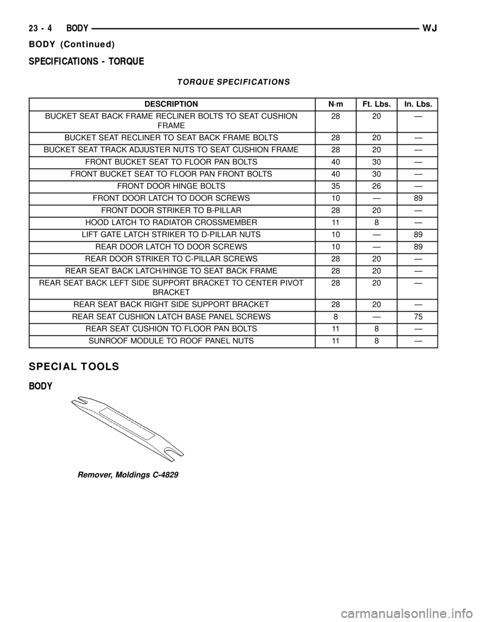
Remover, Moldings C-4829
23 - 4 BODYWJ
BODY (Continued)