Page 1846 of 2199
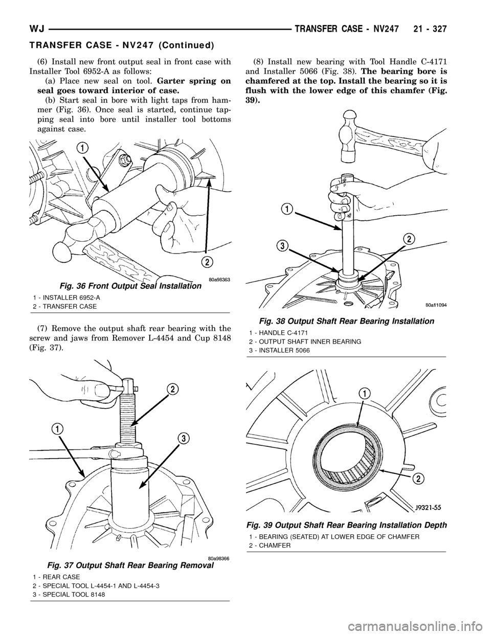
(6) Install new front output seal in front case with
Installer Tool 6952-A as follows:
(a) Place new seal on tool.Garter spring on
seal goes toward interior of case.
(b) Start seal in bore with light taps from ham-
mer (Fig. 36). Once seal is started, continue tap-
ping seal into bore until installer tool bottoms
against case.
(7) Remove the output shaft rear bearing with the
screw and jaws from Remover L-4454 and Cup 8148
(Fig. 37).(8) Install new bearing with Tool Handle C-4171
and Installer 5066 (Fig. 38).The bearing bore is
chamfered at the top. Install the bearing so it is
flush with the lower edge of this chamfer (Fig.
39).
Fig. 37 Output Shaft Rear Bearing Removal
1 - REAR CASE
2 - SPECIAL TOOL L-4454-1 AND L-4454-3
3 - SPECIAL TOOL 8148
Fig. 36 Front Output Seal Installation
1 - INSTALLER 6952-A
2 - TRANSFER CASE
Fig. 38 Output Shaft Rear Bearing Installation
1 - HANDLE C-4171
2 - OUTPUT SHAFT INNER BEARING
3 - INSTALLER 5066
Fig. 39 Output Shaft Rear Bearing Installation Depth
1 - BEARING (SEATED) AT LOWER EDGE OF CHAMFER
2 - CHAMFER
WJTRANSFER CASE - NV247 21 - 327
TRANSFER CASE - NV247 (Continued)
Page 1847 of 2199
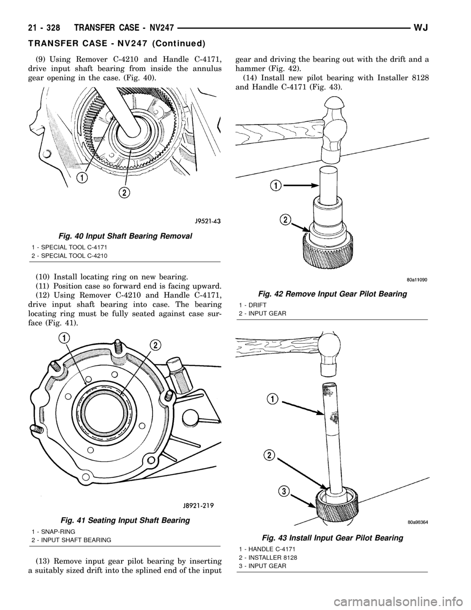
(9) Using Remover C-4210 and Handle C-4171,
drive input shaft bearing from inside the annulus
gear opening in the case. (Fig. 40).
(10) Install locating ring on new bearing.
(11) Position case so forward end is facing upward.
(12) Using Remover C-4210 and Handle C-4171,
drive input shaft bearing into case. The bearing
locating ring must be fully seated against case sur-
face (Fig. 41).
(13) Remove input gear pilot bearing by inserting
a suitably sized drift into the splined end of the inputgear and driving the bearing out with the drift and a
hammer (Fig. 42).
(14) Install new pilot bearing with Installer 8128
and Handle C-4171 (Fig. 43).
Fig. 40 Input Shaft Bearing Removal
1 - SPECIAL TOOL C-4171
2 - SPECIAL TOOL C-4210
Fig. 41 Seating Input Shaft Bearing
1 - SNAP-RING
2 - INPUT SHAFT BEARING
Fig. 42 Remove Input Gear Pilot Bearing
1 - DRIFT
2 - INPUT GEAR
Fig. 43 Install Input Gear Pilot Bearing
1 - HANDLE C-4171
2 - INSTALLER 8128
3 - INPUT GEAR
21 - 328 TRANSFER CASE - NV247WJ
TRANSFER CASE - NV247 (Continued)
Page 1848 of 2199

(15) Remove front bearing retainer seal with suit-
able pry tool.
(16) Install new front bearing retainer with
Installer 7884 (Fig. 44).
INPUT AND LOW RANGE GEAR
(1) Lubricate gears and thrust washers (Fig. 45)
with transfer case lubricant.
(2) Install first thrust washer in low range gear
(Fig. 45). Be sure washer tabs are properly aligned in
gear notches.
(3) Install input gear in low range gear. Be sure
input gear is fully seated.
(4) Install remaining thrust washer in low range
gear and on top of input gear. Be sure washer tabs
are properly aligned in gear notches.
(5) Install retainer on input gear and install snap-
ring.
(6) Align and install low range/input gear assem-
bly in front case (Fig. 46). Be sure low range gear
pinions are engaged in annulus gear and that input
gear shaft is fully seated in front bearing.
Fig. 44 Install Front Bearing Retainer Seal
1 - FRONT BEARING RETAINER
2 - SPECIAL TOOL 7884
Fig. 45 Input/Low Range Gear Components
1 - SNAP-RING
2 - RETAINER PLATE
3 - INPUT GEAR
4 - LOW RANGE GEAR
5 - THRUST WASHERS
Fig. 46 Input/Low Range Gear Installation
1 - ANNULUS GEAR
2 - INPUT/LOW RANGE GEAR
WJTRANSFER CASE - NV247 21 - 329
TRANSFER CASE - NV247 (Continued)
Page 1851 of 2199
(6) Install roller bearings if removed.
(7) Install progressive coupling (Fig. 55).
(8) Install the progressive coupling thrust washer
over the output shaft and against the coupling.
(9) Install the oil pump locating snap-ring onto the
output shaft.(10) Install oil pickup tube in rear case. Be sure
tube is seated in case notch as shown (Fig. 56).
(11) Install magnet in front case pocket (Fig. 57).
Fig. 54 Installing Drive Sprocket Snap-Ring
1 - MAINSHAFT DRIVE SPROCKET
2 - DRIVE SPROCKET SNAP-RING
3 - SNAP-RING PLIERS
Fig. 55 Progressive Coupling Installation
1 - SNAP-RING
2 - PROGRESSIVE COUPLING
Fig. 56 Oil Pickup Tube Installation
1 - CASE NOTCH
2 - OIL PICKUP TUBE ASSEMBLY
3 - CASE SLOT
Fig. 57 Installing Case Magnet
1 - MAGNET
21 - 332 TRANSFER CASE - NV247WJ
TRANSFER CASE - NV247 (Continued)
Page 1852 of 2199
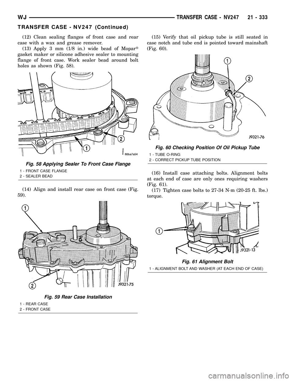
(12) Clean sealing flanges of front case and rear
case with a wax and grease remover.
(13) Apply 3 mm (1/8 in.) wide bead of Mopart
gasket maker or silicone adhesive sealer to mounting
flange of front case. Work sealer bead around bolt
holes as shown (Fig. 58).
(14) Align and install rear case on front case (Fig.
59).(15) Verify that oil pickup tube is still seated in
case notch and tube end is pointed toward mainshaft
(Fig. 60).
(16) Install case attaching bolts. Alignment bolts
at each end of case are only ones requiring washers
(Fig. 61).
(17) Tighten case bolts to 27-34 N´m (20-25 ft. lbs.)
torque.
Fig. 58 Applying Sealer To Front Case Flange
1 - FRONT CASE FLANGE
2 - SEALER BEAD
Fig. 59 Rear Case Installation
1 - REAR CASE
2 - FRONT CASE
Fig. 60 Checking Position Of Oil Pickup Tube
1 - TUBE O-RING
2 - CORRECT PICKUP TUBE POSITION
Fig. 61 Alignment Bolt
1 - ALIGNMENT BOLT AND WASHER (AT EACH END OF CASE)
WJTRANSFER CASE - NV247 21 - 333
TRANSFER CASE - NV247 (Continued)
Page 1857 of 2199

FLUID
STANDARD PROCEDURE - FLUID DRAIN/
REFILL
The fill and drain plugs are both in the rear case
(Fig. 72).
(1) Raise vehicle.
(2) Position drain pan under transfer case.
(3) Remove drain and fill plugs and drain lubri-
cant completely.
(4) Install drain plug. Tighten plug to 20-34 N´m
(15-25 ft. lbs.).
(5) Remove drain pan.(6) Fill transfer case to bottom edge of fill plug
opening with MopartTransfer Case Lubricant.
(7) Install and tighten fill plug to 20-34 N´m
(15-25 ft. lbs.).
(8) Lower vehicle.
FRONT OUTPUT SHAFT SEAL
REMOVAL
(1) Raise vehicle on hoist.
(2) Remove front propeller shaft. (Refer to 3 - DIF-
FERENTIAL & DRIVELINE/PROPELLER SHAFT/
PROPELLER SHAFT - REMOVAL)
(3) Remove front output shaft companion shaft.
(4) Remove seal from front case with pry tool (Fig.
73).
INSTALLATION
(1) Install new front output seal in front case with
Installer Tool 6952-A as follows:
(a) Place new seal on tool. Garter spring on seal
goes toward interior of case.
(b) Start seal in bore with light taps from ham-
mer (Fig. 74). Once seal is started, continue tap-
ping seal into bore until installer tool seats against
case.
(2) Install companion flange and torque nut to
122-176 N´m (90-130 ft. lbs.).
(3) Install front propeller shaft. (Refer to 3 - DIF-
FERENTIAL & DRIVELINE/PROPELLER SHAFT/
PROPELLER SHAFT - INSTALLATION)
Installer, Bearign - 8128
Installer, Seal - 7884
Fig. 72 Fill/Drain Plug and I.D. Tag Location -
Typical
1 - I.D. TAG
2 - FILL PLUG
3 - DRAIN PLUG
Fig. 73 Remove Front Output Shaft Seal
1 - OUTPUT SHAFT SEAL
2 - PRYBAR
21 - 338 TRANSFER CASE - NV247WJ
TRANSFER CASE - NV247 (Continued)
Page 1858 of 2199
REAR RETAINER BUSHING
AND SEAL
REMOVAL
(1) Raise vehicle on hoist.
(2) Remove rear propeller shaft. (Refer to 3 - DIF-
FERENTIAL & DRIVELINE/PROPELLER SHAFT/
PROPELLER SHAFT - REMOVAL)
(3) Using a suitable pry tool or slide-hammer
mounted screw, remove the rear retainer seal.
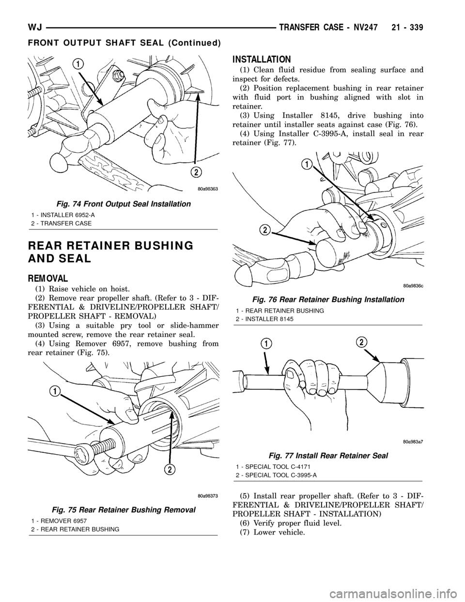
(4) Using Remover 6957, remove bushing from
rear retainer (Fig. 75).
INSTALLATION
(1) Clean fluid residue from sealing surface and
inspect for defects.
(2) Position replacement bushing in rear retainer
with fluid port in bushing aligned with slot in
retainer.
(3) Using Installer 8145, drive bushing into
retainer until installer seats against case (Fig. 76).
(4) Using Installer C-3995-A, install seal in rear
retainer (Fig. 77).
(5) Install rear propeller shaft. (Refer to 3 - DIF-
FERENTIAL & DRIVELINE/PROPELLER SHAFT/
PROPELLER SHAFT - INSTALLATION)
(6) Verify proper fluid level.
(7) Lower vehicle.
Fig. 74 Front Output Seal Installation
1 - INSTALLER 6952-A
2 - TRANSFER CASE
Fig. 75 Rear Retainer Bushing Removal
1 - REMOVER 6957
2 - REAR RETAINER BUSHING
Fig. 76 Rear Retainer Bushing Installation
1 - REAR RETAINER BUSHING
2 - INSTALLER 8145
Fig. 77 Install Rear Retainer Seal
1 - SPECIAL TOOL C-4171
2 - SPECIAL TOOL C-3995-A
WJTRANSFER CASE - NV247 21 - 339
FRONT OUTPUT SHAFT SEAL (Continued)
Page 1859 of 2199
SHIFT CABLE
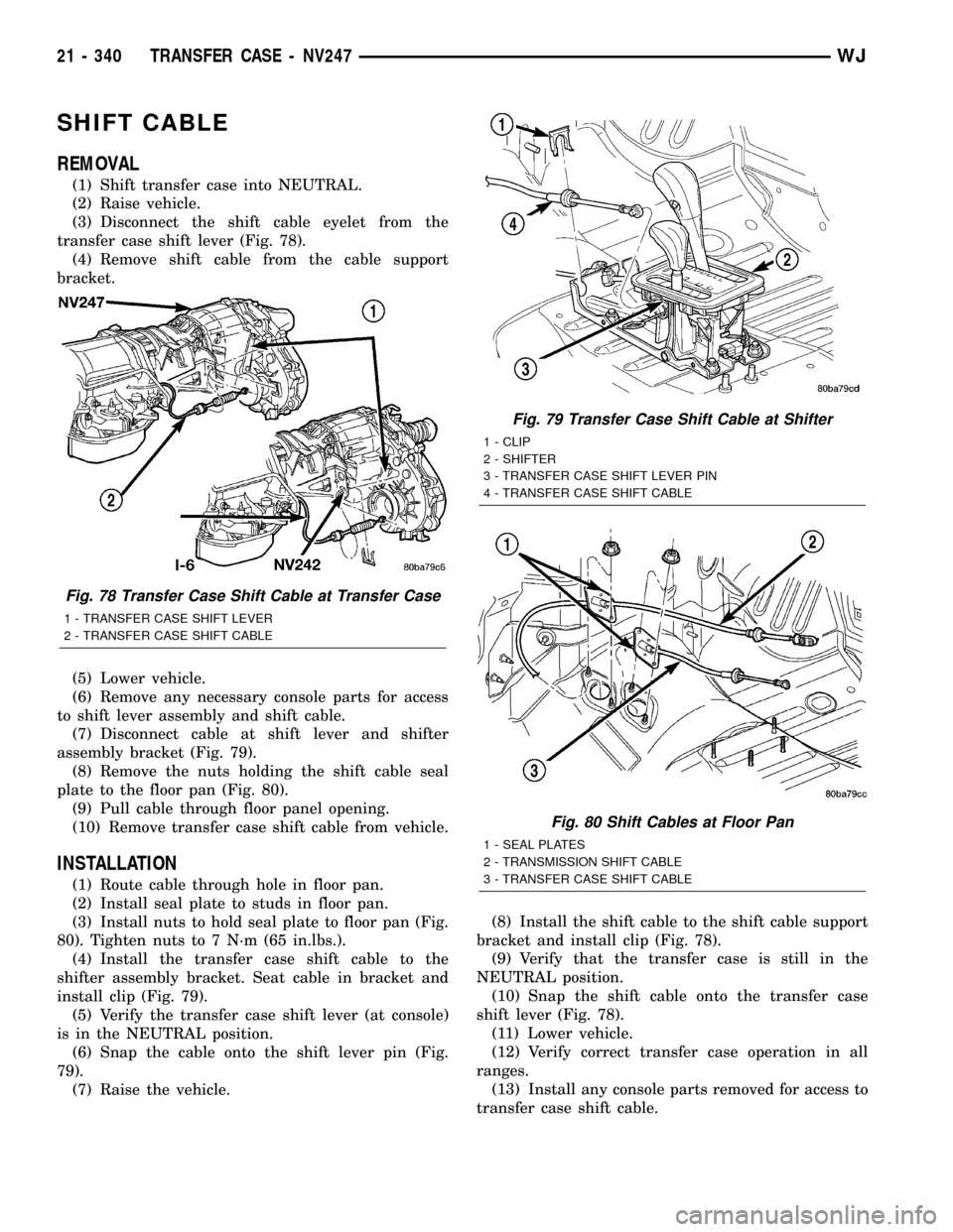
REMOVAL
(1) Shift transfer case into NEUTRAL.
(2) Raise vehicle.
(3) Disconnect the shift cable eyelet from the
transfer case shift lever (Fig. 78).
(4) Remove shift cable from the cable support
bracket.
(5) Lower vehicle.
(6) Remove any necessary console parts for access
to shift lever assembly and shift cable.
(7) Disconnect cable at shift lever and shifter
assembly bracket (Fig. 79).
(8) Remove the nuts holding the shift cable seal
plate to the floor pan (Fig. 80).
(9) Pull cable through floor panel opening.
(10) Remove transfer case shift cable from vehicle.
INSTALLATION
(1) Route cable through hole in floor pan.
(2) Install seal plate to studs in floor pan.
(3) Install nuts to hold seal plate to floor pan (Fig.
80). Tighten nuts to 7 N´m (65 in.lbs.).
(4) Install the transfer case shift cable to the
shifter assembly bracket. Seat cable in bracket and
install clip (Fig. 79).
(5) Verify the transfer case shift lever (at console)
is in the NEUTRAL position.
(6) Snap the cable onto the shift lever pin (Fig.
79).
(7) Raise the vehicle.(8) Install the shift cable to the shift cable support
bracket and install clip (Fig. 78).
(9) Verify that the transfer case is still in the
NEUTRAL position.
(10) Snap the shift cable onto the transfer case
shift lever (Fig. 78).
(11) Lower vehicle.
(12) Verify correct transfer case operation in all
ranges.
(13) Install any console parts removed for access to
transfer case shift cable.
Fig. 78 Transfer Case Shift Cable at Transfer Case
1 - TRANSFER CASE SHIFT LEVER
2 - TRANSFER CASE SHIFT CABLE
Fig. 79 Transfer Case Shift Cable at Shifter
1 - CLIP
2 - SHIFTER
3 - TRANSFER CASE SHIFT LEVER PIN
4 - TRANSFER CASE SHIFT CABLE
Fig. 80 Shift Cables at Floor Pan
1 - SEAL PLATES
2 - TRANSMISSION SHIFT CABLE
3 - TRANSFER CASE SHIFT CABLE
21 - 340 TRANSFER CASE - NV247WJ