2003 JEEP GRAND CHEROKEE Valve cover gasket
[x] Cancel search: Valve cover gasketPage 1341 of 2199

VISUAL TEST METHOD
With the engine cool, remove the coolant pressure
cap. Start the engine and allow it to warm up until
thermostat opens.
If a large combustion/compression pressure leak
exists, bubbles will be visible in the coolant.
COOLING SYSTEM TESTER METHOD
WARNING: WITH COOLING SYSTEM TESTER IN
PLACE, PRESSURE WILL BUILD UP FAST. EXCES-
SIVE PRESSURE BUILT UP, BY CONTINUOUS
ENGINE OPERATION, MUST BE RELEASED TO A
SAFE PRESSURE POINT. NEVER PERMIT PRES-
SURE TO EXCEED 138 kPa (20 psi).
Install Cooling System Tester 7700 or equivalent to
pressure cap neck. Start the engine and observe the
tester's pressure gauge. If gauge pulsates with every
power stroke of a cylinder a combustion pressure
leak is evident.
CHEMICAL TEST METHOD
Combustion leaks into the cooling system can also
be checked by using Bloc-Chek Kit C-3685-A or
equivalent. Perform test following the procedures
supplied with the tool kit.
DIAGNOSIS AND TESTING - HYDRAULIC LASH
ADJUSTER
A tappet-like noise may be produced from several
items. Check the following items.
(1) Engine oil level too high or too low. This may
cause aerated oil to enter the adjusters and cause
them to be spongy.
(2) Insufficient running time after rebuilding cylin-
der head. Low speed running up to 1 hour may be
required.
(3) Turn engine off and let set for a few minutes
before restarting. Repeat this several times after
engine has reached normal operating temperature.
(4) Low oil pressure.
(5) The oil restrictor in cylinder head gasket or the
oil passage to the cylinder head is plugged with
debris.
(6) Air ingested into oil due to broken or cracked
oil pump pick up.
(7) Worn valve guides.
(8) Rocker arm ears contacting valve spring
retainer.
(9) Rocker arm loose, adjuster stuck or at maxi-
mum extension and still leaves lash in the system.
(10) Oil leak or excessive cam bore wear in cylin-
der head.
(11) Faulty lash adjuster.a. Check lash adjusters for sponginess while
installed in cylinder head and cam on camshaft at
base circle. Depress part of rocker arm over adjuster.
Normal adjusters should feel very firm. Spongy
adjusters can be bottomed out easily.
b. Remove suspected lash adjusters, and replace.
c. Before installation, make sure adjusters are at
least partially full of oil. This can be verified by little
or no plunger travel when lash adjuster is depressed.
REMOVAL
(1) Disconnect battery negitive cable.
(2) Raise the vehicle on a hoist.
(3) Disconnect the exhaust pipe at the right side
exhaust manifold.
(4) Drain the engine coolant (Refer to 7 - COOL-
ING - STANDARD PROCEDURE).
(5) Lower the vehicle.
(6) Remove the intake manifold (Refer to 9 -
ENGINE/MANIFOLDS/INTAKE MANIFOLD -
REMOVAL).
(7) Remove the cylinder head cover (Refer to 9 -
ENGINE/CYLINDER HEAD/CYLINDER HEAD
COVER(S) - REMOVAL).
(8) Remove oil fill housing from cylinder head.
(9) Remove accessory drive belt (Refer to 7 -
COOLING/ACCESSORY DRIVE/DRIVE BELTS -
REMOVAL).
(10) Rotate the crankshaft until the damper tim-
ing mark is aligned with TDC indicator mark (Fig.
9).
(11) Verify the V8 mark on the camshaft sprocket
is at the 12 o'clock position (Fig. 11). Rotate the
crankshaft one turn if necessary.
(12) Remove the crankshaft damper (Refer to 9 -
ENGINE/ENGINE BLOCK/VIBRATION DAMPER -
REMOVAL).
(13) Remove the timing chain cover (Refer to 9 -
ENGINE/VALVE TIMING/TIMING BELT / CHAIN
COVER(S) - REMOVAL).
(14) Lock the secondary timing chains to the idler
sprocket using Special Tool 8515 (Fig. 10).
NOTE: Mark the secondary timing chain prior to
removal to aid in installation.
(15) Mark the secondary timing chain, one link on
each side of the V8 mark on the camshaft drive gear
(Fig. 11).
(16) Remove the right side secondary chain ten-
sioner (Refer to 9 - ENGINE/VALVE TIMING/TIM-
ING BELT/CHAIN AND SPROCKETS - REMOVAL).
(17) Remove the cylinder head access plug (Fig.
29).
(18) Remove the right side secondary chain guide
(Refer to 9 - ENGINE/VALVE TIMING/TIMING
BELT/CHAIN AND SPROCKETS - REMOVAL).
9 - 98 ENGINE - 4.7LWJ
CYLINDER HEAD - RIGHT (Continued)
Page 1347 of 2199

CYLINDER HEAD COVER(S) -
RIGHT
DESCRIPTION
The cylinder head covers are made of die cast mag-
nesium, and are not interchangeable from side-to-
side. It is imperative that nothing rest on the
cylinder head covers. Prolonged contact with other
items may wear a hole in the cylinder head cover.
REMOVAL - RIGHT SIDE
(1) Disconnect battery negative cable.
(2) Remove air cleaner assembly, resonator assem-
bly and air inlet hose.
(3) Drain cooling system (Refer to 7 - COOLING -
STANDARD PROCEDURE).
(4) Remove accessory drive belt (Refer to 7 -
COOLING/ACCESSORY DRIVE/DRIVE BELTS -
REMOVAL).
(5) Remove air conditioning compressor retaining
bolts and move compressor to the left.
(6) Remove heater hoses.
(7) Disconnect injector and ignition coil connectors.
(8) Disconnect and remove positive crankcase ven-
tilation (PCV) hose.
(9) Remove oil fill tube.
(10) Un-clip injector and ignition coil harness and
move away from cylinder head cover.
(11) Remove right rear breather tube and filter
assembly.
(12) Remove cylinder head cover retaining bolts.
(13) Remove cylinder head cover.
NOTE: The gasket may be used again, provided no
cuts, tears, or deformation has occurred.
CLEANING
Clean cylinder head cover gasket surface.
Clean head rail, if necessary.
INSTALLATION - RIGHT SIDE
CAUTION: Do not use harsh cleaners to clean the
cylinder head covers. Severe damage to covers
may occur.
CAUTION: DO NOT allow other components includ-
ing the wire harness to rest on or against the
engine cylinder head cover. Prolonged contact with
other objects may wear a hole in the cylinder head
cover.
(1) Clean cylinder head cover and both sealing sur-
faces. Inspect and replace gasket as necessary.(2) Install cylinder head cover and hand start all
fasteners. Verify that all double ended studs are in
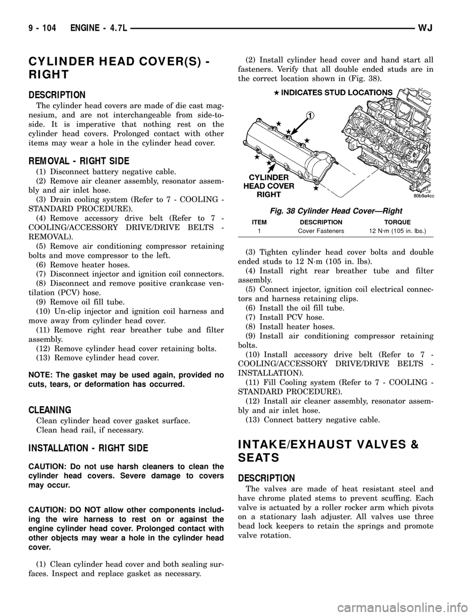
the correct location shown in (Fig. 38).
(3) Tighten cylinder head cover bolts and double
ended studs to 12 N´m (105 in. lbs).
(4) Install right rear breather tube and filter
assembly.
(5) Connect injector, ignition coil electrical connec-
tors and harness retaining clips.
(6) Install the oil fill tube.
(7) Install PCV hose.
(8) Install heater hoses.
(9) Install air conditioning compressor retaining
bolts.
(10) Install accessory drive belt (Refer to 7 -
COOLING/ACCESSORY DRIVE/DRIVE BELTS -
INSTALLATION).
(11) Fill Cooling system (Refer to 7 - COOLING -
STANDARD PROCEDURE).
(12) Install air cleaner assembly, resonator assem-
bly and air inlet hose.
(13) Connect battery negative cable.
INTAKE/EXHAUST VALVES &
SEATS
DESCRIPTION
The valves are made of heat resistant steel and
have chrome plated stems to prevent scuffing. Each
valve is actuated by a roller rocker arm which pivots
on a stationary lash adjuster. All valves use three
bead lock keepers to retain the springs and promote
valve rotation.
Fig. 38 Cylinder Head CoverÐRight
ITEM DESCRIPTION TORQUE
1 Cover Fasteners 12 N´m (105 in. lbs.)
9 - 104 ENGINE - 4.7LWJ
Page 1371 of 2199

ENGINE LUBRICATION FLOW CHARTÐBLOCK: TABLE 1
FROM TO
Oil Pickup Tube Oil Pump
Oil Pump Oil Filter
Oil Filter Block Main Oil Gallery
Block Main Oil Gallery 1. Crankshaft Main Journal
2. Left Cylinder Head*
3. Right Cylinder Head*
Crankshaft Main Journals Crankshaft Rod Journals
Crankshaft Number One Main Journal 1.Front Timing Chain Idler Shaft
2.Both Secondary Chain Tensioners
Left Cylinder Head See Table 2
Right Cylinder Head See Table 2
* The cylinder head
gaskets have an oil restricter to control oil flow to the cylinder heads.
ENGINE LUBRICATION FLOW CHARTÐCYLINDER HEADS: TABLE 2
FROM TO
Cylinder Head Oil Port (in bolt hole) Diagonal Cross Drilling to Main Oil Gallery
Main Oil Gallery (drilled through head from rear to
front)1. Base of Camshaft Towers
2. Lash Adjuster Towers
Base of Camshaft Towers Vertical Drilling Through Tower to Camshaft Bearings**
Lash Adjuster Towers Diagonal Drillings to Hydraulic Lash Adjuster Pockets
** The number three camshaft bearing journal feeds oil into the hollow camshaft tubes. Oil is routed to the intake
lobes, which have oil passages drilled into them to lubricate the rocker arms.
DIAGNOSIS AND TESTING
DIAGNOSIS AND TESTINGÐENGINE OIL
PRESSURE
(1) Remove oil pressure sending unit (Fig. 89)and
install gauge assembly C-3292.
(2) Run engine until thermostat opens.
(3) Oil Pressure:
²Curb IdleÐ25 Kpa (4 psi) minimum
²3000 rpmÐ170 - 550 KPa (25 - 80 psi)
(4) If oil pressure is 0 at idle, shut off engine.
Check for a clogged oil pick-up screen or a pressure
relief valve stuck open.
DIAGNOSIS AND TESTINGÐREAR SEAL AREA
LEAKS
Since it is sometimes difficult to determine the
source of an oil leak in the rear seal area of the
engine, a more involved inspection is necessary. The
following steps should be followed to help pinpoint
the source of the leak.If the leakage occurs at the crankshaft rear oil seal
area:
(1) Disconnect the battery.
(2) Raise the vehicle.
(3) Remove torque converter or clutch housing
cover and inspect rear of block for evidence of oil.
Use a black light to check for the oil leak:
(a) Circular spray pattern generally indicates
seal leakage or crankshaft damage.
(b) Where leakage tends to run straight down,
possible causes are a porous block, distributor seal,
camshaft bore cup plugs, oil galley pipe plugs, oil
filter runoff, and main bearing cap to cylinder
block mating surfaces. See Engine, for proper
repair procedures of these items.
(4) If no leaks are detected, pressurized the crank-
case as outlined in the section, Inspection (Engine oil
Leaks in general)
CAUTION: Do not exceed 20.6 kPa (3 psi).
9 - 128 ENGINE - 4.7LWJ
LUBRICATION (Continued)
Page 1657 of 2199

Fig. 258 Lower Housing Shift Valves and Springs
1 - 3-4 ACCUMULATOR HOUSING 11 - TIMING VALVE COVER
2 - 3-4 SHIFT VALVE AND SPRING 12 - PLUG
3 - PLUG 13 - 3-4 TIMING VALVE AND SPRING
4 - SPRING RETAINER 14 - LOWER HOUSING
5 - CONVERTER CLUTCH VALVE AND SPRING 15 - ACCUMULATOR END PLATE
6 - CONVERTER CLUTCH TIMING VALVE AND SPRING 16 - 3-4 ACCUMULATOR PISTON AND SPRING
7 - OVERDRIVE SEPARATOR PLATE 17 - E-CLIP
8 - CASE CONNECTOR 18 - 3-4 QUICK FILL SPRING AND VALVE
9 - CONVERTER CLUTCH SOLENOID 19 - SOLENOID GASKET
10 - OVERDRIVE SOLENOID 20 - HARNESS
21 - 138 AUTOMATIC TRANSMISSION - 42REWJ
VALVE BODY (Continued)
Page 1684 of 2199

VALVE BODY LOWER HOUSING
(1) Remove timing valve cover.
(2) Remove 3-4 timing valve and spring.
(3) Remove 3-4 quick fill valve, spring and plug.
(4) Remove 3-4 shift valve and spring.
(5) Remove converter clutch valve, spring and plug
(Fig. 309).
(6) Remove converter clutch timing valve, retainer
and valve spring.
3-4 ACCUMULATOR HOUSING
(1) Remove end plate from housing.
(2) Remove piston spring.
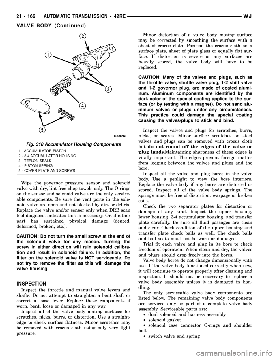
(3) Remove piston. Remove and discard piston
seals (Fig. 310).
CLEANING
Clean the valve housings, valves, plugs, springs,
and separator plates with a standard parts cleaning
solution only. Do not use gasoline, kerosene, or any
type of caustic solution.
Do not immerse any of the electrical components in
cleaning solution. Clean the governor solenoid and
sensor and the dual solenoid and harness assembly
by wiping them off with dry shop towels only.
Dry all except the electrical parts with compressed
air. Make sure all passages are clean and free from
obstructions.Do not use rags or shop towels to
dry or wipe off valve body components. Lint
from these materials can stick to valve body
parts, interfere with valve operation, and clog
filters and fluid passages.
Fig. 309 Lower Housing Shift Valves and Springs
1 - 3-4 ACCUMULATOR HOUSING 11 - TIMING VALVE COVER
2 - 3-4 SHIFT VALVE AND SPRING 12 - PLUG
3 - PLUG 13 - 3-4 TIMING VALVE AND SPRING
4 - SPRING RETAINER 14 - LOWER HOUSING
5 - CONVERTER CLUTCH VALVE AND SPRING 15 - ACCUMULATOR END PLATE
6 - CONVERTER CLUTCH TIMING VALVE AND SPRING 16 - 3-4 ACCUMULATOR PISTON AND SPRING
7 - OVERDRIVE SEPARATOR PLATE 17 - E-CLIP
8 - CASE CONNECTOR 18 - 3-4 QUICK FILL SPRING AND VALVE
9 - CONVERTER CLUTCH SOLENOID 19 - SOLENOID GASKET
10 - OVERDRIVE SOLENOID 20 - HARNESS
WJAUTOMATIC TRANSMISSION - 42RE 21 - 165
VALVE BODY (Continued)
Page 1685 of 2199

Wipe the governor pressure sensor and solenoid
valve with dry, lint free shop towels only. The O-rings
on the sensor and solenoid valve are the only service-
able components. Be sure the vent ports in the sole-
noid valve are open and not blocked by dirt or debris.
Replace the valve and/or sensor only when DRB scan
tool diagnosis indicates this is necessary. Or, if either
part has sustained physical damage (dented,
deformed, broken, etc.).
CAUTION: Do not turn the small screw at the end of
the solenoid valve for any reason. Turning the
screw in either direction will ruin solenoid calibra-
tion and result in solenoid failure. In addition, the
filter on the solenoid valve is NOT serviceable. Do
not try to remove the filter as this will damage the
valve housing.
INSPECTION
Inspect the throttle and manual valve levers and
shafts. Do not attempt to straighten a bent shaft or
correct a loose lever. Replace these components if
worn, bent, loose or damaged in any way.
Inspect all of the valve body mating surfaces for
scratches, nicks, burrs, or distortion. Use a straight-
edge to check surface flatness. Minor scratches may
be removed with crocus cloth using only very light
pressure.Minor distortion of a valve body mating surface
may be corrected by smoothing the surface with a
sheet of crocus cloth. Position the crocus cloth on a
surface plate, sheet of plate glass or equally flat sur-
face. If distortion is severe or any surfaces are
heavily scored, the valve body will have to be
replaced.
CAUTION: Many of the valves and plugs, such as
the throttle valve, shuttle valve plug, 1-2 shift valve
and 1-2 governor plug, are made of coated alumi-
num. Aluminum components are identified by the
dark color of the special coating applied to the sur-
face (or by testing with a magnet). Do not sand alu-
minum valves or plugs under any circumstances.
This practice could damage the special coating
causing the valves/plugs to stick and bind.
Inspect the valves and plugs for scratches, burrs,
nicks, or scores. Minor surface scratches on steel
valves and plugs can be removed with crocus cloth
butdo not round off the edges of the valve or
plug lands.Maintaining sharpness of these edges is
vitally important. The edges prevent foreign matter
from lodging between the valves and plugs and the
bore.
Inspect all the valve and plug bores in the valve
body. Use a penlight to view the bore interiors.
Replace the valve body if any bores are distorted or
scored. Inspect all of the valve body springs. The
springs must be free of distortion, warpage or broken
coils.
Check the two separator plates for distortion or
damage of any kind. Inspect the upper housing,
lower housing, 3-4 accumulator housing, and transfer
plate carefully. Be sure all fluid passages are clean
and clear. Check condition of the upper housing and
transfer plate check balls as well. The check balls
and ball seats must not be worn or damaged.
Trial fit each valve and plug in its bore to check
freedom of operation. When clean and dry, the valves
and plugs should drop freely into the bores.
Valve body bores do not change dimensionally with
use. If the valve body functioned correctly when new,
it will continue to operate properly after cleaning and
inspection. It should not be necessary to replace a
valve body assembly unless it is damaged in han-
dling.
The only serviceable valve body components are
listed below. The remaining valve body components
are serviced only as part of a complete valve body
assembly. Serviceable parts are:
²dual solenoid and harness assembly
²solenoid gasket
²solenoid case connector O-rings and shoulder
bolt
²switch valve and spring
Fig. 310 Accumulator Housing Components
1 - ACCUMULATOR PISTON
2 - 3-4 ACCUMULATOR HOUSING
3 - TEFLON SEALS
4 - PISTON SPRING
5 - COVER PLATE AND SCREWS
21 - 166 AUTOMATIC TRANSMISSION - 42REWJ
VALVE BODY (Continued)
Page 1693 of 2199

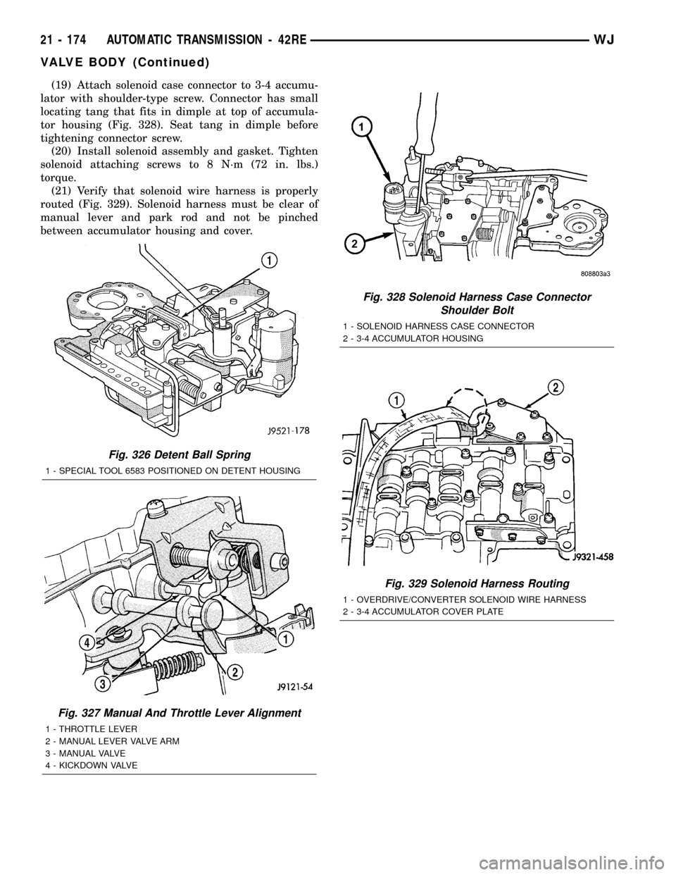
(19) Attach solenoid case connector to 3-4 accumu-
lator with shoulder-type screw. Connector has small
locating tang that fits in dimple at top of accumula-
tor housing (Fig. 328). Seat tang in dimple before
tightening connector screw.
(20) Install solenoid assembly and gasket. Tighten
solenoid attaching screws to 8 N´m (72 in. lbs.)
torque.
(21) Verify that solenoid wire harness is properly
routed (Fig. 329). Solenoid harness must be clear of
manual lever and park rod and not be pinched
between accumulator housing and cover.
Fig. 326 Detent Ball Spring
1 - SPECIAL TOOL 6583 POSITIONED ON DETENT HOUSING
Fig. 327 Manual And Throttle Lever Alignment
1 - THROTTLE LEVER
2 - MANUAL LEVER VALVE ARM
3 - MANUAL VALVE
4 - KICKDOWN VALVE
Fig. 328 Solenoid Harness Case Connector
Shoulder Bolt
1 - SOLENOID HARNESS CASE CONNECTOR
2 - 3-4 ACCUMULATOR HOUSING
Fig. 329 Solenoid Harness Routing
1 - OVERDRIVE/CONVERTER SOLENOID WIRE HARNESS
2 - 3-4 ACCUMULATOR COVER PLATE
21 - 174 AUTOMATIC TRANSMISSION - 42REWJ
VALVE BODY (Continued)
Page 2143 of 2199

REMOVAL
(1) Disconnect and isolate the battery negative
cable.
(2) Recover the refrigerant from the A/C system-
(Refer to 24 - HEATING & AIR CONDITIONING/
PLUMBING - STANDARD PROCEDURE).
(3) Disconnect the the A/C lines from the expan-
sion valve. Cap or tape over the open A/C lines.
(4) Remove the lines from the expansion valve(Re-
fer to 24 - HEATING & AIR CONDITIONING/
PLUMBING/LIQUID LINE - REMOVAL), (Refer to
24 - HEATING & AIR CONDITIONING/PLUMBING/
LIQUID LINE - REMOVAL), (Refer to 24 - HEAT-
ING & AIR CONDITIONING/PLUMBING/A/C
DISCHARGE LINE - REMOVAL) and (Refer to 24 -
HEATING & AIR CONDITIONING/PLUMBING/A/C
DISCHARGE LINE - REMOVAL).
(5) Remove the expansion valve retainer screw
from the expansion valve.
(6) Remove the expansion valve.
(7) Remove the expansion valve gasket.
INSTALLATION
(1) Install a NEW gasket and install the eapansion
valve to the evaporator.
(2) Install the expansion valve bolts and tighten to
11 N´m (100 in. lbs.).
(3) Install NEW seals on the A/C lines and install
the lines to the expansion valve(Refer to 24 - HEAT-
ING & AIR CONDITIONING/PLUMBING/A/C DIS-
CHARGE LINE - INSTALLATION), (Refer to 24 -
HEATING & AIR CONDITIONING/PLUMBING/A/C
DISCHARGE LINE - INSTALLATION), (Refer to 24
- HEATING & AIR CONDITIONING/PLUMBING/
LIQUID LINE - INSTALLATION) and (Refer to 24 -
HEATING & AIR CONDITIONING/PLUMBING/
LIQUID LINE - INSTALLATION).
(4) Evacuate the A/C system(Refer to 24 - HEAT-
ING & AIR CONDITIONING/PLUMBING - STAN-
DARD PROCEDURE).
(5) Recharge the A/C system(Refer to 24 - HEAT-
ING & AIR CONDITIONING/PLUMBING - STAN-
DARD PROCEDURE).
(6) Connect the battery negative cable.
LIQUID LINE
REMOVAL
REMOVAL
WARNING: REVIEW THE WARNINGS AND CAU-
TIONS IN THE FRONT OF THIS SECTION BEFORE
PERFORMING THE FOLLOWING OPERATION.(Refer to 24 - HEATING & AIR CONDITIONING/
PLUMBING - WARNING) (Refer to 24 - HEATING &
AIR CONDITIONING/PLUMBING - CAUTION)
(1) The liquid line is serviced as an integral part of
the receiver/drier assembly(Refer to 24 - HEATING
& AIR CONDITIONING/PLUMBING/RECEIVER /
DRIER - REMOVAL) or (Refer to 24 - HEATING &
AIR CONDITIONING/PLUMBING/RECEIVER /
DRIER - REMOVAL).
REMOVAL - 2.7L TURBO DIESEL
WARNING: REVIEW THE WARNINGS AND CAU-
TIONS IN THE FRONT OF THIS SECTION BEFORE
PERFORMING THE FOLLOWING OPERATION.
(Refer to 24 - HEATING & AIR CONDITIONING/
PLUMBING - WARNING) (Refer to 24 - HEATING &
AIR CONDITIONING/PLUMBING - CAUTION)
(1) The liquid line is service as an integral part of
the receiver/drier assembly(Refer to 24 - HEATING
& AIR CONDITIONING/PLUMBING/RECEIVER /
DRIER - REMOVAL).
INSTALLATION
INSTALLATION
WARNING: REVIEW THE WARNINGS AND CAU-
TIONS IN THE FRONT OF THIS SECTION BEFORE
PERFORMING THE FOLLOWING OPERATION.
(Refer to 24 - HEATING & AIR CONDITIONING/
PLUMBING - WARNING) (Refer to 24 - HEATING &
AIR CONDITIONING/PLUMBING - CAUTION)
Any kinks or sharp bends in the refrigerant plumb-
ing will reduce the capacity of the entire air condi-
tioning system. Kinks and sharp bends reduce the
flow of refrigerant in the system. A good rule for the
flexible hose refrigerant lines is to keep the radius of
all bends at least ten times the diameter of the hose.
In addition, the flexible hose refrigerant lines should
be routed so they are at least 80 millimeters (3
inches) from the exhaust manifold.
High pressures are produced in the refrigerant sys-
tem when the air conditioning compressor is operat-
ing. Extreme care must be exercised to make sure
that each of the refrigerant system connections is
pressure-tight and leak free. It is a good practice to
inspect all flexible hose refrigerant lines at least once
a year to make sure they are in good condition and
properly routed.
(1) The liquid line is serviced as an integral part of
the receiver/drier assembly(Refer to 24 - HEATING
& AIR CONDITIONING/PLUMBING/RECEIVER /
DRIER - INSTALLATION) or (Refer to 24 - HEAT-
24 - 66 PLUMBINGWJ
A/C EXPANSION VALVE (Continued)