2003 JEEP GRAND CHEROKEE Valve cover gasket
[x] Cancel search: Valve cover gasketPage 1301 of 2199

(3) Install intake manifold on the cylinder head
dowels.
(4) Install washer and fastener Numbers 1, 2, 4, 5,
8, 9, 10 and 11 (Fig. 84).
(5) Install washer and fastener Numbers 6 and 7
(Fig. 84).
(6) Tighten the fasteners in sequence and to the
specified torque (Fig. 84).
²Fastener Numbers 1 through 5ÐTighten to 33
N´m (24 ft. lbs.) torque.
²Fastener Numbers 6 and 7ÐTighten to 31 N´m
(23 ft. lbs.) torque.
²Fastener Numbers 8 through 11ÐTighten to 33
N´m (24 ft. lbs.) torque.
(7) Install the power steering pump to the intake
manifold.
(8) Install the accessory drive belt (Refer to 7 -
COOLING/ACCESSORY DRIVE/DRIVE BELTS -
INSTALLATION).
(9) Install the fuel system supply line to the fuel
rail assembly.
(10) Connect all electrical connections on the
intake manifold.
(11) Connect the vacuum hoses previously
removed.
(12) Install throttle cable, vehicle speed control
cable (if equipped).
(13) Install the transmission line pressure cable (if
equipped) (Refer to 21 - TRANSMISSION/TRANS-
AXLE/AUTOMATIC - AW4/THROTTLE VALVE
CABLE - INSTALLATION).
(14) Install air cleaner assembly.
(15) Connect air inlet hose to the resonator assem-
bly.
(16) Raise the vehicle.
(17) Connect the exhaust pipes to the engine
exhaust manifolds. Tighten the bolts to 31 N´m (23
ft. lbs.)
(18) Lower the vehicle.(19) Connect the battery negative cable.
(20) Start the engine and check for leaks.
EXHAUST MANIFOLD
DESCRIPTION
The two exhaust manifolds (Fig. 85) are log style
and are made of high silicon molybdenum cast iron.
The exhaust manifolds share a common gasket with
the intake manifold. The exhaust manifolds also
incorporate ball flange outlets for improved sealing
and strain free connections.
REMOVAL
The intake and engine exhaust manifolds on the
4.0L engine must be removed together. The manifolds
use a common gasket at the cylinder head.
(Refer to 9 - ENGINE/MANIFOLDS/INTAKE
MANIFOLD - REMOVAL).
INSTALLATION
(1) The exhaust manifold and the intake manifold
must be installed together using a common gasket.
(2) (Refer to 9 - ENGINE/MANIFOLDS/INTAKE
MANIFOLD - INSTALLATION).
TIMING BELT / CHAIN
COVER(S)
REMOVAL
(1) Disconnect negative cable from battery.
(2) Remove the vibration damper (Refer to 9 -
ENGINE/ENGINE BLOCK/VIBRATION DAMPER -
REMOVAL).
(3) Remove the fan, hub assembly and fan shroud
(Refer to 7 - COOLING/ENGINE/RADIATOR FAN -
REMOVAL).
(4) Remove the accessory drive brackets that are
attached to the timing case cover.
(5) Remove the A/C compressor (Refer to 24 -
HEATING & AIR CONDITIONING/PLUMBING/A/C
COMPRESSOR - REMOVAL) (if equipped) and gen-
erator bracket assembly from the engine cylinder
head and move to one side.
(6) Remove the oil pan-to-timing case cover bolts
and timing case cover-to-cylinder block bolts.
(7) Remove the timing case cover and gasket from
the engine.
(8) Pry the crankshaft oil seal from the front of the
timing case cover (Fig. 86).
INSTALLATION
Clean the timing case cover, oil pan and cylinder
block gasket surfaces.
Fig. 84 Intake and Exhaust Manifolds Installation
9 - 58 ENGINE - 4.0LWJ
INTAKE MANIFOLD (Continued)
Page 1303 of 2199
TIMING BELT/CHAIN AND
SPROCKETS
REMOVAL
(1) Disconnect negative cable from battery.
(2) Remove the fan and shroud (Refer to 7 -
COOLING/ENGINE/RADIATOR FAN - REMOVAL).
(3) Remove the serpentine drive belt (Refer to 7 -
COOLING/ACCESSORY DRIVE/DRIVE BELTS -
REMOVAL).
(4) Remove the crankshaft vibration damper (Refer
to 9 - ENGINE/ENGINE BLOCK/VIBRATION
DAMPER - REMOVAL).
(5) Remove the timing case cover (Refer to 9 -
ENGINE/VALVE TIMING/TIMING BELT / CHAIN
COVER(S) - REMOVAL).
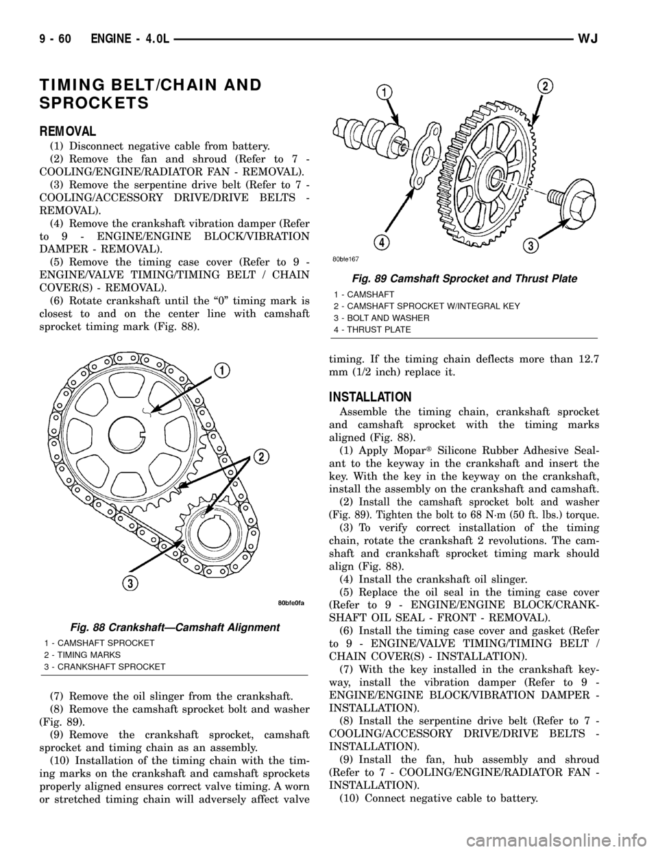
(6) Rotate crankshaft until the ª0º timing mark is
closest to and on the center line with camshaft
sprocket timing mark (Fig. 88).
(7) Remove the oil slinger from the crankshaft.
(8) Remove the camshaft sprocket bolt and washer
(Fig. 89).
(9) Remove the crankshaft sprocket, camshaft
sprocket and timing chain as an assembly.
(10) Installation of the timing chain with the tim-
ing marks on the crankshaft and camshaft sprockets
properly aligned ensures correct valve timing. A worn
or stretched timing chain will adversely affect valvetiming. If the timing chain deflects more than 12.7
mm (1/2 inch) replace it.
INSTALLATION
Assemble the timing chain, crankshaft sprocket
and camshaft sprocket with the timing marks
aligned (Fig. 88).
(1) Apply MopartSilicone Rubber Adhesive Seal-
ant to the keyway in the crankshaft and insert the
key. With the key in the keyway on the crankshaft,
install the assembly on the crankshaft and camshaft.
(2)
Install the camshaft sprocket bolt and washer
(Fig. 89). Tighten the bolt to 68 N´m (50 ft. lbs.) torque.
(3) To verify correct installation of the timing
chain, rotate the crankshaft 2 revolutions. The cam-
shaft and crankshaft sprocket timing mark should
align (Fig. 88).
(4) Install the crankshaft oil slinger.
(5) Replace the oil seal in the timing case cover
(Refer to 9 - ENGINE/ENGINE BLOCK/CRANK-
SHAFT OIL SEAL - FRONT - REMOVAL).
(6) Install the timing case cover and gasket (Refer
to 9 - ENGINE/VALVE TIMING/TIMING BELT /
CHAIN COVER(S) - INSTALLATION).
(7) With the key installed in the crankshaft key-
way, install the vibration damper (Refer to 9 -
ENGINE/ENGINE BLOCK/VIBRATION DAMPER -
INSTALLATION).
(8) Install the serpentine drive belt (Refer to 7 -
COOLING/ACCESSORY DRIVE/DRIVE BELTS -
INSTALLATION).
(9) Install the fan, hub assembly and shroud
(Refer to 7 - COOLING/ENGINE/RADIATOR FAN -
INSTALLATION).
(10) Connect negative cable to battery.
Fig. 88 CrankshaftÐCamshaft Alignment
1 - CAMSHAFT SPROCKET
2 - TIMING MARKS
3 - CRANKSHAFT SPROCKET
Fig. 89 Camshaft Sprocket and Thrust Plate
1 - CAMSHAFT
2 - CAMSHAFT SPROCKET W/INTEGRAL KEY
3 - BOLT AND WASHER
4 - THRUST PLATE
9 - 60 ENGINE - 4.0LWJ
Page 1304 of 2199
ENGINE - 4.7L
TABLE OF CONTENTS
page page
ENGINE - 4.7L
DESCRIPTIONÐ4.7L ENGINE.............63
DIAGNOSIS AND TESTING
DIAGNOSIS AND TESTING - ENGINE
DIAGNOSIS - INTRODUCTION...........64
DIAGNOSIS AND TESTING - ENGINE
DIAGNOSIS - PERFORMANCE...........65
DIAGNOSIS AND TESTING - ENGINE
DIAGNOSIS - MECHANICAL.............66
DIAGNOSIS AND TESTING - ENGINE
DIAGNOSIS - LUBRICATION.............67
DIAGNOSIS AND TESTING - CYLINDER
COMPRESSION PRESSURE.............68
DIAGNOSIS AND TESTING - CYLINDER
COMBUSTION PRESSURE LEAKAGE......69
STANDARD PROCEDURE
STANDARD PROCEDURE - REPAIR
DAMAGED OR WORN THREADS.........70
STANDARD PROCEDURE - FORM-IN-
PLACE GASKETS AND SEALERS.........70
STANDARD PROCEDURE - ENGINE
GASKET SURFACE PREPARATION........70
STANDARD PROCEDURE - ENGINE CORE
AND OIL GALLERY PLUGS..............71
REMOVAL.............................71
INSTALLATION.........................73
SPECIFICATIONS
4.7L ENGINE.........................74
SPECIFICATIONS - 4.7L H.O. ENGINE.....77
TORQUE............................79
SPECIAL TOOLS
4.7L ENGINE.........................80
AIR CLEANER ELEMENT
REMOVAL - 4.7L........................83
INSTALLATION - 4.7L....................83
AIR CLEANER HOUSING
REMOVAL - 4.7L........................84
INSTALLATION - 4.7L....................84
CYLINDER HEAD - LEFT
DESCRIPTION
DESCRIPTION - CYLINDER HEAD........84
DESCRIPTION - VALVE GUIDES..........84
DIAGNOSIS AND TESTING
DIAGNOSIS AND TESTING - HYDRAULIC
LASH ADJUSTER.....................84
DIAGNOSIS AND TESTINGÐCYLINDER
HEAD GASKET.......................85
REMOVAL.............................85
CLEANING............................86
INSPECTION..........................87INSTALLATION.........................87
CAMSHAFT(S) - LEFT
DESCRIPTION.........................88
REMOVAL.............................89
INSTALLATION.........................90
CYLINDER HEAD COVER(S) - LEFT
DESCRIPTION.........................93
REMOVAL - LEFT SIDE..................93
CLEANING............................93
INSTALLATIONÐLEFT SIDE...............93
INTAKE/EXHAUST VALVES & SEATS
DESCRIPTION.........................94
STANDARD PROCEDUREÐREFACING......94
REMOVAL.............................94
INSTALLATION.........................95
ROCKER ARM / ADJUSTER ASSEMBLY
DESCRIPTION.........................96
REMOVAL.............................96
INSTALLATION.........................96
VALVE SPRINGS
DESCRIPTION.........................97
VALVE STEM SEALS
DESCRIPTION.........................97
CYLINDER HEAD - RIGHT
DESCRIPTION
DESCRIPTION - CYLINDER HEAD........97
DESCRIPTION - VALVE GUIDES..........97
DIAGNOSIS AND TESTING
DIAGNOSIS AND TESTINGÐCYLINDER
HEAD GASKET.......................97
DIAGNOSIS AND TESTING - HYDRAULIC
LASH ADJUSTER.....................98
REMOVAL.............................98
CLEANING............................99
INSPECTION..........................99
INSTALLATION.........................99
CAMSHAFT(S) - RIGHT
DESCRIPTION........................100
REMOVAL............................100
INSTALLATION........................102
CYLINDER HEAD COVER(S) - RIGHT
DESCRIPTION........................104
REMOVAL - RIGHT SIDE................104
CLEANING...........................104
INSTALLATION - RIGHT SIDE.............104
INTAKE/EXHAUST VALVES & SEATS
DESCRIPTION........................104
STANDARD PROCEDUREÐREFACING.....105
REMOVAL............................105
INSTALLATION........................106
WJENGINE - 4.7L 9 - 61
Page 1319 of 2199
DESCRIPTION SPECIFICATION
Exhaust 36.87 - 37.13 mm
1.4516 - 1.4618 in.)
Length (Overall)
Intake 113.45 - 114.21 mm
(4.4666 - 4.4965)
Exhaust 114.92 - 115.68 mm
(4.5244 - 4.5543 in.)
Stem Diameter
Intake 6.931 - 6.957 mm
(0.2729 - 0.2739 in.)
Exhaust 6.902 - 6.928 mm
(0.2717 - 0.2728 in.)
Stem - to - Guide
Clearance
Intake .018 - .069 mm
(0.0008 - 0.0028 in.)
Exhaust .047 - .098 mm
(0.0019 - 0.0039 in.)
Max. Allowable Stem -
to -
Guide Clearance
(Rocking
Method)
Intake 0.069 mm (0.0028 in.)
Exhaust 0.098 mm (0.0039 in.)
Valve Lift (Zero Lash)
Intake 11.25 mm (0.443 in.)
Exhaust 10.90 mm (0.4292 in.)
VALVE SPRING
Free Length (Approx)
Intake and Exhaust 48.6 mm (1.9134 in.)
Spring Force (Valve
Closed)
Intake and Exhaust 315.5 - 352.5 N @ 40.89
mm
(70.92722 - 79.24515 lbs.
@ 1.6099 in.)DESCRIPTION SPECIFICATION
Spring Force (Valve
Open)
Intake and Exhaust 786.0 - 860.0 N @ 29.64
mm
176.6998 - 193.3357 lbs.
@ 1.167 in.)
Number of Coils
Intake and Exhaust 6.69
Wire Diameter
Intake and Exhaust 4.2799 - 4.3561 mm
(0.1685 - 0.1715 in.)
Installed Height (Spring
Seat to Bottom of
Retainer)
Nominal
Intake 40.97 mm (1.613 in.)
Exhaust 40.81 mm (1.606 in.)
CYLINDER HEAD
Gasket Thickness
(Compressed) .7 mm (0.0276 in.)
Valve Seat Angle 44.5É - 45.0É
Valve Seat Runout (MAX) 0.051 mm (0.002 in.)
Valve Seat Width
Intake 1.75 - 2.36 mm
(0.0698 - 0.0928 in.)
Exhaust 1.71 - 2.32 mm
(0.0673 - 0.0911 in.)
Guide Bore Diameter
(Std.)6.975 - 7.00 mm
(0.2747 - 0.2756 in.)
Cylinder Head Warpage
(Flatness) 0.0508 mm (0.002 in.)
OIL PUMP
Clearance Over Rotors /
End Face (MAX).035 - .095 mm
(0.0014 - 0.0038 in.)
Cover Out - of -Flat
(MAX).025 mm (0.001 in.)
Inner and Outer Rotor
Thickness 12.02 mm (0.4731 in.)
9 - 76 ENGINE - 4.7LWJ
ENGINE - 4.7L (Continued)
Page 1322 of 2199
DESCRIPTION SPECIFICATION
Valve Lift (Zero Lash)
Intake 12.00 mm (0.4724 in.)
Exhaust 10.90 mm (0.4292 in.)
VALVE SPRING
Free Length (Approx)
Intake and Exhaust 48.92 mm (1.9259 in.)
Spring Force (Valve
Closed)
Intake and Exhaust 380.0 +/- 19.0 N @ 40.12
mm
(85.4274 lbs. @ 1.5795
in.)
Spring Force (Valve
Open)
Intake and Exhaust 1030.0 +/- 46.0 N @
28.12 mm
231.5532 lbs. @ 1.107
in.)
Number of Coils
Intake and Exhaust 7.30
Wire Diameter
Intake and Exhaust 4.77 +/- 0.03 mm x
3.80+/- .03mm
Installed Height (Spring
Seat to Bottom of
Retainer)
Nominal
Intake 40.97 mm (1.613 in.)
Exhaust 40.81 mm (1.606 in.)
CYLINDER HEAD
Gasket Thickness
(Compressed) .7 mm (0.0276 in.)
Valve Seat Angle 44.5É - 45.0É
Valve Seat Runout (MAX) 0.051 mm (0.002 in.)
Valve Seat Width
Intake 1.75 - 2.36 mm
(0.0698 - 0.0928 in.)
Exhaust 1.71 - 2.32 mm
(0.0673 - 0.0911 in.)
Guide Bore Diameter
(Std.)6.975 - 7.00 mm
(0.2747 - 0.2756 in.)DESCRIPTION SPECIFICATION
Cylinder Head Warpage
(Flatness) 0.0508 mm (0.002 in.)
OIL PUMP
Clearance Over Rotors /
End Face (MAX).035 - .095 mm
(0.0014 - 0.0038 in.)
Cover Out - of -Flat
(MAX).025 mm (0.001 in.)
Inner and Outer Rotor
Thickness 12.02 mm (0.4731 in.)
Outer Rotor Clearance
(MAX).235 mm (.0093 in.)
Outer Rotor Diameter
(MIN)85.925 mm (0.400 in.)
Tip Clearance Between
Rotors
(MAX) .150 mm (0.006 in.)
OIL PRESSURE
At Curb Idle Speed
(MIN)*25 kPa (4 psi)
@ 3000 rpm 170 - 758 kPa (25 - 110
psi)
* CAUTION: If pressure is zero at curb idle, DO
NOT run
engine at 3000 rpm.
TORQUE
DESCRIPTION N´m Ft. In.
Lbs. Lbs.
Camshaft
Non - Oiled Sprocket Bolt 122 90 Ð
Bearing Cap Bolts 11 Ð 100
Timing Chain CoverÐBolts 54 40 Ð
Connecting Rod CapÐBolts 27 20 Ð
PLUS 90É TURN
Bed PlateÐBolts Refer to Procedure
Crankshaft DamperÐBolt 175 130 Ð
Cylinder HeadÐBolts
M11 Bolts 81 60 Ð
M8 Bolts 26 19 Ð
Cylinder Head CoverÐBolts 12 Ð 105
Exhaust ManifoldÐBolts 25 18 Ð
WJENGINE - 4.7L 9 - 79
ENGINE - 4.7L (Continued)
Page 1328 of 2199
(3) Turn engine off and let set for a few minutes
before restarting. Repeat this several times after
engine has reached normal operating temperature.
(4) Low oil pressure.
(5) The oil restrictor in cylinder head gasket or the
oil passage to the cylinder head is plugged with
debris.
(6) Air ingested into oil due to broken or cracked
oil pump pick up.
(7) Worn valve guides.
(8) Rocker arm ears contacting valve spring
retainer.
(9) Rocker arm loose, adjuster stuck or at maxi-
mum extension and still leaves lash in the system.
(10) Oil leak or excessive cam bore wear in cylin-
der head.
(11) Faulty lash adjuster.
a. Check lash adjusters for sponginess while
installed in cylinder head and cam on camshaft at
base circle. Depress part of rocker arm over adjuster.
Normal adjusters should feel very firm. Spongy
adjusters can be bottomed out easily.
b. Remove suspected lash adjusters, and replace.
c. Before installation, make sure adjusters are at
least partially full of oil. This can be verified by little
or no plunger travel when lash adjuster is depressed.
DIAGNOSIS AND TESTINGÐCYLINDER HEAD
GASKET
A cylinder head gasket leak can be located between
adjacent cylinders or between a cylinder and the
adjacent water jacket.
Possible indications of the cylinder head gasket
leaking between adjacent cylinders are:
²Loss of engine power
²Engine misfiring
²Poor fuel economy
Possible indications of the cylinder head gasket
leaking between a cylinder and an adjacent water
jacket are:
²Engine overheating
²Loss of coolant
²Excessive steam (white smoke) emitting from
exhaust
²Coolant foaming
CYLINDER-TO-CYLINDER LEAKAGE TEST
To determine if an engine cylinder head gasket is
leaking between adjacent cylinders, follow the proce-
dures in Cylinder Compression Pressure Test (Refer
to 9 - ENGINE - DIAGNOSIS AND TESTING). An
engine cylinder head gasket leaking between adja-
cent cylinders will result in approximately a 50±70%
reduction in compression pressure.
CYLINDER-TO-WATER JACKET LEAKAGE TEST
WARNING: USE EXTREME CAUTION WHEN THE
ENGINE IS OPERATING WITH COOLANT PRES-
SURE CAP REMOVED.
VISUAL TEST METHOD
With the engine cool, remove the coolant pressure
cap. Start the engine and allow it to warm up until
thermostat opens.
If a large combustion/compression pressure leak
exists, bubbles will be visible in the coolant.
COOLING SYSTEM TESTER METHOD
WARNING: WITH COOLING SYSTEM TESTER IN
PLACE, PRESSURE WILL BUILD UP FAST. EXCES-
SIVE PRESSURE BUILT UP, BY CONTINUOUS
ENGINE OPERATION, MUST BE RELEASED TO A
SAFE PRESSURE POINT. NEVER PERMIT PRES-
SURE TO EXCEED 138 kPa (20 psi).
Install Cooling System Tester 7700 or equivalent to
pressure cap neck. Start the engine and observe the
tester's pressure gauge. If gauge pulsates with every
power stroke of a cylinder a combustion pressure
leak is evident.
CHEMICAL TEST METHOD
Combustion leaks into the cooling system can also
be checked by using Bloc-Chek Kit C-3685-A or
equivalent. Perform test following the procedures
supplied with the tool kit.
REMOVAL
(1) Disconnect the negative cable from the battery.
(2) Raise the vehicle on a hoist.
(3) Disconnect the exhaust pipe at the left side
exhaust manifold.
(4) Drain the engine coolant. (Refer to 7 - COOL-
ING - STANDARD PROCEDURE).
(5) Lower the vehicle.
(6) Remove the intake manifold. (Refer to 9 -
ENGINE/MANIFOLDS/INTAKE MANIFOLD -
REMOVAL).
(7) Remove the cylinder head cover. (Refer to 9 -
ENGINE/CYLINDER HEAD/CYLINDER HEAD
COVER(S) - REMOVAL).
(8) Remove accessory drive belt. (Refer to 7 -
COOLING/ACCESSORY DRIVE/DRIVE BELTS -
REMOVAL).
(9) Remove the power steering pump and set
aside.
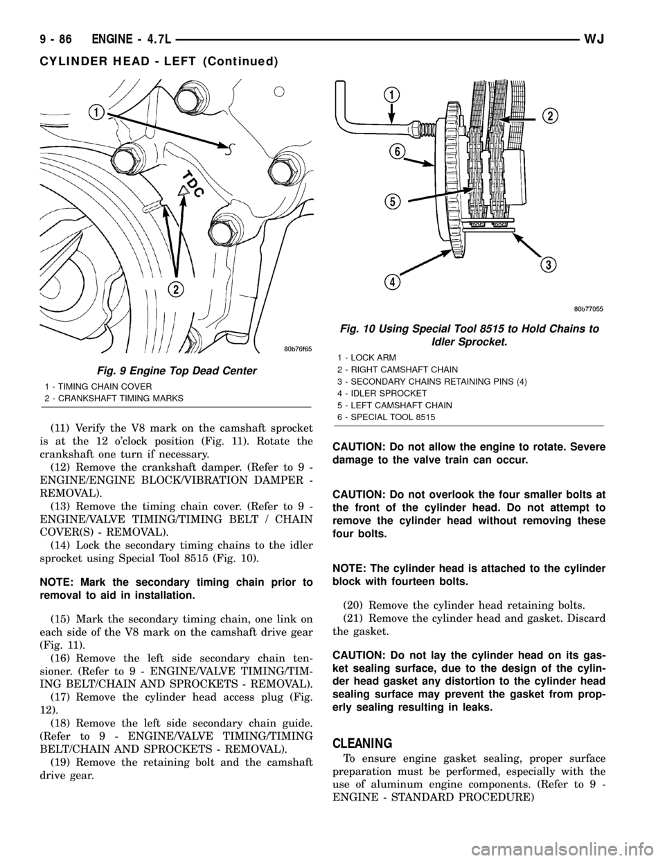
(10) Rotate the crankshaft until the damper tim-
ing mark is aligned with TDC indicator mark (Fig.
9).
WJENGINE - 4.7L 9 - 85
CYLINDER HEAD - LEFT (Continued)
Page 1329 of 2199
(11) Verify the V8 mark on the camshaft sprocket
is at the 12 o'clock position (Fig. 11). Rotate the
crankshaft one turn if necessary.
(12) Remove the crankshaft damper. (Refer to 9 -
ENGINE/ENGINE BLOCK/VIBRATION DAMPER -
REMOVAL).
(13) Remove the timing chain cover. (Refer to 9 -
ENGINE/VALVE TIMING/TIMING BELT / CHAIN
COVER(S) - REMOVAL).
(14) Lock the secondary timing chains to the idler
sprocket using Special Tool 8515 (Fig. 10).
NOTE: Mark the secondary timing chain prior to
removal to aid in installation.
(15) Mark the secondary timing chain, one link on
each side of the V8 mark on the camshaft drive gear
(Fig. 11).
(16) Remove the left side secondary chain ten-
sioner. (Refer to 9 - ENGINE/VALVE TIMING/TIM-
ING BELT/CHAIN AND SPROCKETS - REMOVAL).
(17) Remove the cylinder head access plug (Fig.
12).
(18) Remove the left side secondary chain guide.
(Refer to 9 - ENGINE/VALVE TIMING/TIMING
BELT/CHAIN AND SPROCKETS - REMOVAL).
(19) Remove the retaining bolt and the camshaft
drive gear.CAUTION: Do not allow the engine to rotate. Severe
damage to the valve train can occur.
CAUTION: Do not overlook the four smaller bolts at
the front of the cylinder head. Do not attempt to
remove the cylinder head without removing these
four bolts.
NOTE: The cylinder head is attached to the cylinder
block with fourteen bolts.
(20) Remove the cylinder head retaining bolts.
(21) Remove the cylinder head and gasket. Discard
the gasket.
CAUTION: Do not lay the cylinder head on its gas-
ket sealing surface, due to the design of the cylin-
der head gasket any distortion to the cylinder head
sealing surface may prevent the gasket from prop-
erly sealing resulting in leaks.
CLEANING
To ensure engine gasket sealing, proper surface
preparation must be performed, especially with the
use of aluminum engine components. (Refer to 9 -
ENGINE - STANDARD PROCEDURE)
Fig. 9 Engine Top Dead Center
1 - TIMING CHAIN COVER
2 - CRANKSHAFT TIMING MARKS
Fig. 10 Using Special Tool 8515 to Hold Chains to
Idler Sprocket.
1 - LOCK ARM
2 - RIGHT CAMSHAFT CHAIN
3 - SECONDARY CHAINS RETAINING PINS (4)
4 - IDLER SPROCKET
5 - LEFT CAMSHAFT CHAIN
6 - SPECIAL TOOL 8515
9 - 86 ENGINE - 4.7LWJ
CYLINDER HEAD - LEFT (Continued)
Page 1340 of 2199
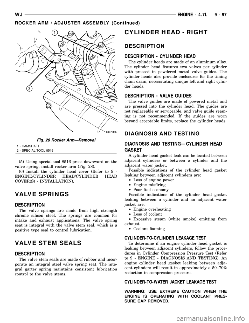
(5) Using special tool 8516 press downward on the
valve spring, install rocker arm (Fig. 28).
(6) Install the cylinder head cover (Refer to 9 -
ENGINE/CYLINDER HEAD/CYLINDER HEAD
COVER(S) - INSTALLATION).
VALVE SPRINGS
DESCRIPTION
The valve springs are made from high strength
chrome silicon steel. The springs are common for
intake and exhaust applications. The valve spring
seat is integral with the valve stem seal, which is a
positive type seal to control lubrication.
VALVE STEM SEALS
DESCRIPTION
The valve stem seals are made of rubber and incor-
porate an integral steel valve spring seat. The inte-
gral garter spring maintains consistent lubrication
control to the valve stems.
CYLINDER HEAD - RIGHT
DESCRIPTION
DESCRIPTION - CYLINDER HEAD
The cylinder heads are made of an aluminum alloy.
The cylinder head features two valves per cylinder
with pressed in powdered metal valve guides. The
cylinder heads also provide enclosures for the timing
chain drain, necessitating unique left and right cylin-
der heads.
DESCRIPTION - VALVE GUIDES
The valve guides are made of powered metal and
are pressed into the cylinder head. The guides are
not replaceable or serviceable, and valve guide ream-
ing is not recommended. If the guides are worn
beyond acceptable limits, replace the cylinder heads.
DIAGNOSIS AND TESTING
DIAGNOSIS AND TESTINGÐCYLINDER HEAD
GASKET
A cylinder head gasket leak can be located between
adjacent cylinders or between a cylinder and the
adjacent water jacket.
Possible indications of the cylinder head gasket
leaking between adjacent cylinders are:
²Loss of engine power
²Engine misfiring
²Poor fuel economy
Possible indications of the cylinder head gasket
leaking between a cylinder and an adjacent water
jacket are:
²Engine overheating
²Loss of coolant
²Excessive steam (white smoke) emitting from
exhaust
²Coolant foaming
CYLINDER-TO-CYLINDER LEAKAGE TEST
To determine if an engine cylinder head gasket is
leaking between adjacent cylinders, follow the proce-
dures in Cylinder Compression Pressure Test (Refer
to 9 - ENGINE - DIAGNOSIS AND TESTING). An
engine cylinder head gasket leaking between adja-
cent cylinders will result in approximately a 50±70%
reduction in compression pressure.
CYLINDER-TO-WATER JACKET LEAKAGE TEST
WARNING: USE EXTREME CAUTION WHEN THE
ENGINE IS OPERATING WITH COOLANT PRES-
SURE CAP REMOVED.
Fig. 28 Rocker ArmÐRemoval
1 - CAMSHAFT
2 - SPECIAL TOOL 8516
WJENGINE - 4.7L 9 - 97
ROCKER ARM / ADJUSTER ASSEMBLY (Continued)