2003 JEEP GRAND CHEROKEE ABS REAR SENSOR
[x] Cancel search: ABS REAR SENSORPage 1051 of 2199
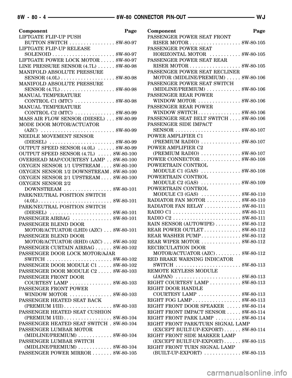
Component Page
LIFTGATE FLIP-UP PUSH
BUTTON SWITCH................ 8W-80-97
LIFTGATE FLIP-UP RELEASE
SOLENOID...................... 8W-80-97
LIFTGATE POWER LOCK MOTOR..... 8W-80-97
LINE PRESSURE SENSOR (4.7L)...... 8W-80-98
MANIFOLD ABSOLUTE PRESSURE
SENSOR (4.0L)................... 8W-80-98
MANIFOLD ABSOLUTE PRESSURE
SENSOR (4.7L)................... 8W-80-98
MANUAL TEMPERATURE
CONTROL C1 (MTC).............. 8W-80-98
MANUAL TEMPERATURE
CONTROL C2 (MTC).............. 8W-80-99
MASS AIR FLOW SENSOR (DIESEL) . . . 8W-80-99
MODE DOOR MOTOR/ACTUATOR
(AZC).......................... 8W-80-99
NEEDLE MOVEMENT SENSOR
(DIESEL)....................... 8W-80-99
OUTPUT SPEED SENSOR (4.0L)...... 8W-80-99
OUTPUT SPEED SENSOR (4.7L)..... 8W-80-100
OVERHEAD MAP/COURTESY LAMP . . 8W-80-100
OXYGEN SENSOR 1/1 UPSTREAM.... 8W-80-100
OXYGEN SENSOR 1/2 DOWNSTREAM . 8W-80-100
OXYGEN SENSOR 2/1 UPSTREAM.... 8W-80-100
OXYGEN SENSOR 2/2
DOWNSTREAM................. 8W-80-101
PARK/NEUTRAL POSITION SWITCH
(4.0L).......................... 8W-80-101
PARK/NEUTRAL POSITION SWITCH
(DIESEL)...................... 8W-80-101
PASSENGER AIRBAG.............. 8W-80-101
PASSENGER BLEND DOOR
MOTOR/ACTUATOR (LHD) (AZC) . . . 8W-80-101
PASSENGER BLEND DOOR
MOTOR/ACTUATOR (RHD) (AZC) . . . 8W-80-102
PASSENGER CURTAIN AIRBAG...... 8W-80-102
PASSENGER DOOR LOCK MOTOR/AJAR
SWITCH....................... 8W-80-102
PASSENGER DOOR MODULE C1..... 8W-80-102
PASSENGER DOOR MODULE C2..... 8W-80-103
PASSENGER FRONT DOOR
COURTESY LAMP............... 8W-80-103
PASSENGER FRONT POWER
WINDOW MOTOR............... 8W-80-103
PASSENGER HEATED SEAT BACK
(PREMIUM I/III)................. 8W-80-103
PASSENGER HEATED SEAT CUSHION
(PREMIUM I/III)................. 8W-80-104
PASSENGER HEATED SEAT SWITCH . 8W-80-104
PASSENGER LUMBAR MOTOR
(MIDLINE/PREMIUM)............ 8W-80-104
PASSENGER LUMBAR SWITCH
(MIDLINE/PREMIUM)............ 8W-80-104
PASSENGER POWER MIRROR....... 8W-80-105Component Page
PASSENGER POWER SEAT FRONT
RISER MOTOR.................. 8W-80-105
PASSENGER POWER SEAT
HORIZONTAL MOTOR........... 8W-80-105
PASSENGER POWER SEAT REAR
RISER MOTOR.................. 8W-80-105
PASSENGER POWER SEAT RECLINER
MOTOR (MIDLINE/PREMIUM)..... 8W-80-106
PASSENGER POWER SEAT SWITCH
(MIDLINE/PREMIUM)............ 8W-80-106
PASSENGER REAR POWER
WINDOW MOTOR............... 8W-80-106
PASSENGER REAR POWER
WINDOW SWITCH............... 8W-80-106
PASSENGER SEAT BELT SWITCH.... 8W-80-106
PASSENGER SIDE IMPACT
SENSOR....................... 8W-80-107
POWER AMPLIFIER C1
(PREMIUM RADIO).............. 8W-80-107
POWER AMPLIFIER C2
(PREMIUM RADIO).............. 8W-80-107
POWER CONNECTOR.............. 8W-80-108
POWERTRAIN CONTROL
MODULE C1 (GAS).............. 8W-80-108
POWERTRAIN CONTROL
MODULE C2 (GAS).............. 8W-80-109
POWERTRAIN CONTROL
MODULE C3 (GAS).............. 8W-80-110
RADIATOR FAN MOTOR............ 8W-80-110
RADIATOR FAN RELAY............. 8W-80-111
RADIO C1........................ 8W-80-111
RADIO C2........................ 8W-80-111
RAIN SENSOR (AUTOWIPE)......... 8W-80-112
REAR POWER OUTLET............. 8W-80-112
REAR WASHER PUMP.............. 8W-80-112
REAR WIPER MOTOR.............. 8W-80-112
RECIRCULATION DOOR
MOTOR/ACTUATOR (AZC)......... 8W-80-112
RED BRAKE WARNING INDICATOR
SWITCH....................... 8W-80-113
REMOTE KEYLESS MODULE
(JAPAN)....................... 8W-80-113
RIGHT COURTESY LAMP........... 8W-80-113
RIGHT DOOR HANDLE
COURTESY LAMP............... 8W-80-113
RIGHT FOG LAMP................. 8W-80-113
RIGHT FRONT DOOR SPEAKER..... 8W-80-114
RIGHT FRONT IMPACT SENSOR..... 8W-80-114
RIGHT FRONT PARK LAMP......... 8W-80-114
RIGHT FRONT PARK/TURN SIGNAL LAMP
(EXCEPT BUILT-UP-EXPORT)...... 8W-80-114
RIGHT FRONT SIDE MARKER LAMP
(EXCEPT BUILT-UP-EXPORT)...... 8W-80-115
RIGHT FRONT TURN SIGNAL LAMP
(BUILT-UP-EXPORT)............. 8W-80-115
8W - 80 - 4 8W-80 CONNECTOR PIN-OUTWJ
Page 1145 of 2199
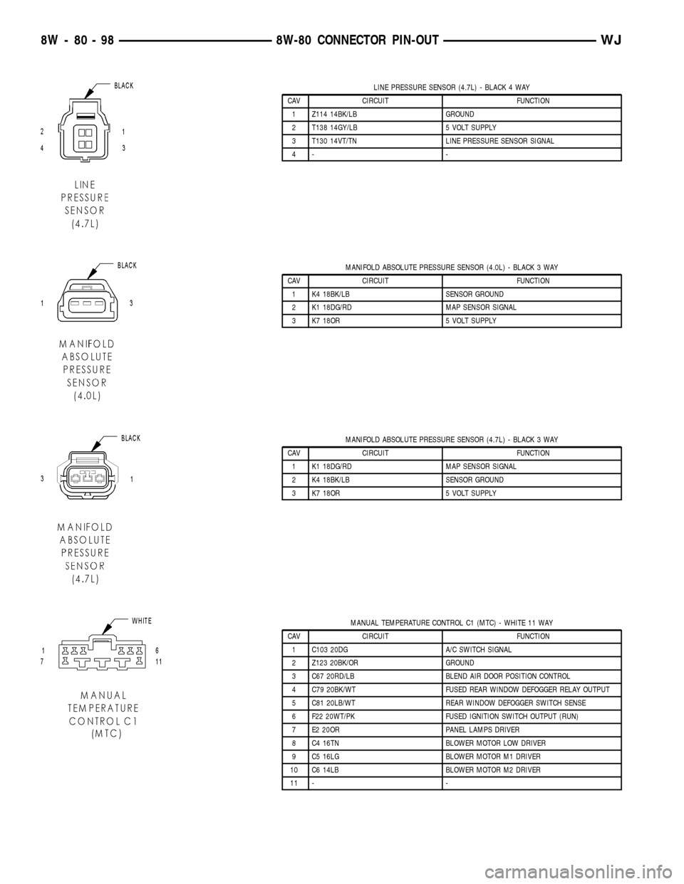
LINE PRESSURE SENSOR (4.7L) - BLACK 4 WAY
CAV CIRCUIT FUNCTION
1 Z114 14BK/LB GROUND
2 T138 14GY/LB 5 VOLT SUPPLY
3 T130 14VT/TN LINE PRESSURE SENSOR SIGNAL
4- -
MANIFOLD ABSOLUTE PRESSURE SENSOR (4.0L) - BLACK 3 WAY
CAV CIRCUIT FUNCTION
1 K4 18BK/LB SENSOR GROUND
2 K1 18DG/RD MAP SENSOR SIGNAL
3 K7 18OR 5 VOLT SUPPLY
MANIFOLD ABSOLUTE PRESSURE SENSOR (4.7L) - BLACK 3 WAY
CAV CIRCUIT FUNCTION
1 K1 18DG/RD MAP SENSOR SIGNAL
2 K4 18BK/LB SENSOR GROUND
3 K7 18OR 5 VOLT SUPPLY
MANUAL TEMPERATURE CONTROL C1 (MTC) - WHITE 11 WAY
CAV CIRCUIT FUNCTION
1 C103 20DG A/C SWITCH SIGNAL
2 Z123 20BK/OR GROUND
3 C67 20RD/LB BLEND AIR DOOR POSITION CONTROL
4 C79 20BK/WT FUSED REAR WINDOW DEFOGGER RELAY OUTPUT
5 C81 20LB/WT REAR WINDOW DEFOGGER SWITCH SENSE
6 F22 20WT/PK FUSED IGNITION SWITCH OUTPUT (RUN)
7 E2 20OR PANEL LAMPS DRIVER
8 C4 16TN BLOWER MOTOR LOW DRIVER
9 C5 16LG BLOWER MOTOR M1 DRIVER
10 C6 14LB BLOWER MOTOR M2 DRIVER
11 - -
8W - 80 - 98 8W-80 CONNECTOR PIN-OUTWJ
Page 1182 of 2199
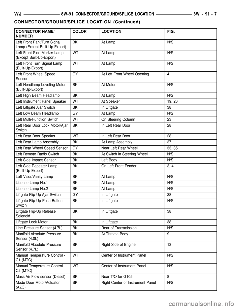
CONNECTOR NAME/
NUMBERCOLOR LOCATION FIG.
Left Front Park/Turn Signal
Lamp (Except Built-Up-Export)BK At Lamp N/S
Left Front Side Marker Lamp
(Except Built-Up-Export)WT At Lamp N/S
Left Front Turn Signal Lamp
(Built-Up-Export)WT At Lamp N/S
Left Front Wheel Speed
SensorGY At Left Front Wheel Opening 4
Left Headlamp Leveling Motor
(Built-Up-Export)BK At Motor N/S
Left High Beam Headlamp BK At Lamp N/S
Left Instrument Panel Speaker WT At Speaker 19, 20
Left Liftgate Ajar Switch BK In Liftgate 38
Left Low Beam Headlamp GY At Lamp N/S
Left Multi-Function Switch WT On Steering Column 23
Left Rear Door Lock Motor/Ajar
SwitchBK In Left Rear Door 28
Left Rear Door Speaker WT In Left Rear Door 28
Left Rear Lamp Assembly BK At Lamp Assembly 37
Left Rear Wheel Speed Sensor GY Near Left Rear Wheel 33, 35
Left Remote Radio Switch BK At Switch in Steering Wheel N/S
Left Side Impact Sensor BK Left Body N/S
Left Side Repeater Lamp
(Built-Up-Export)BK On Left Front Fender 3, 4
Left Visor/Vanity Lamp BK At Lamp N/S
License Lamp No.1 BK At Lamp N/S
License Lamp No.2 BK At Lamp N/S
Liftgate Flip-Up Ajar Switch GY In Liftgate 38
Liftgate Flip-Up Push Button
SwitchBK In Liftgate N/S
Liftgate Flip-Up Release
SolenoidBK In Liftgate 38
Liftgate Lock Motor BK In Liftgate 38
Line Pressure Sensor (4.7L) BK Rear of Transmission N/S
Manifold Absolute Pressure
Sensor (4.0L)BK At Throttle Body 9
Manifold Absolute Pressure
Sensor (4.7L)BK Right Side of Engine 13
Manual Temperature Control -
C1 (MTC)WT Center of Instrument Panel N/S
Manual Temperature Control -
C2 (MTC)WT Center of Instrument Panel N/S
Mass Air Flow sensor (Diesel) BK Near T/O for G105 8
Mode Door Motor/Actuator
(AZC)BK Right Center of Instrument Panel N/S
WJ8W-91 CONNECTOR/GROUND/SPLICE LOCATION 8W - 91 - 7
CONNECTOR/GROUND/SPLICE LOCATION (Continued)
Page 1358 of 2199
CRANKSHAFT MAIN BEARING SELECTION
The main bearings are ªselect fitº to achieve proper
oil clearances. For main bearing selection, the crank-
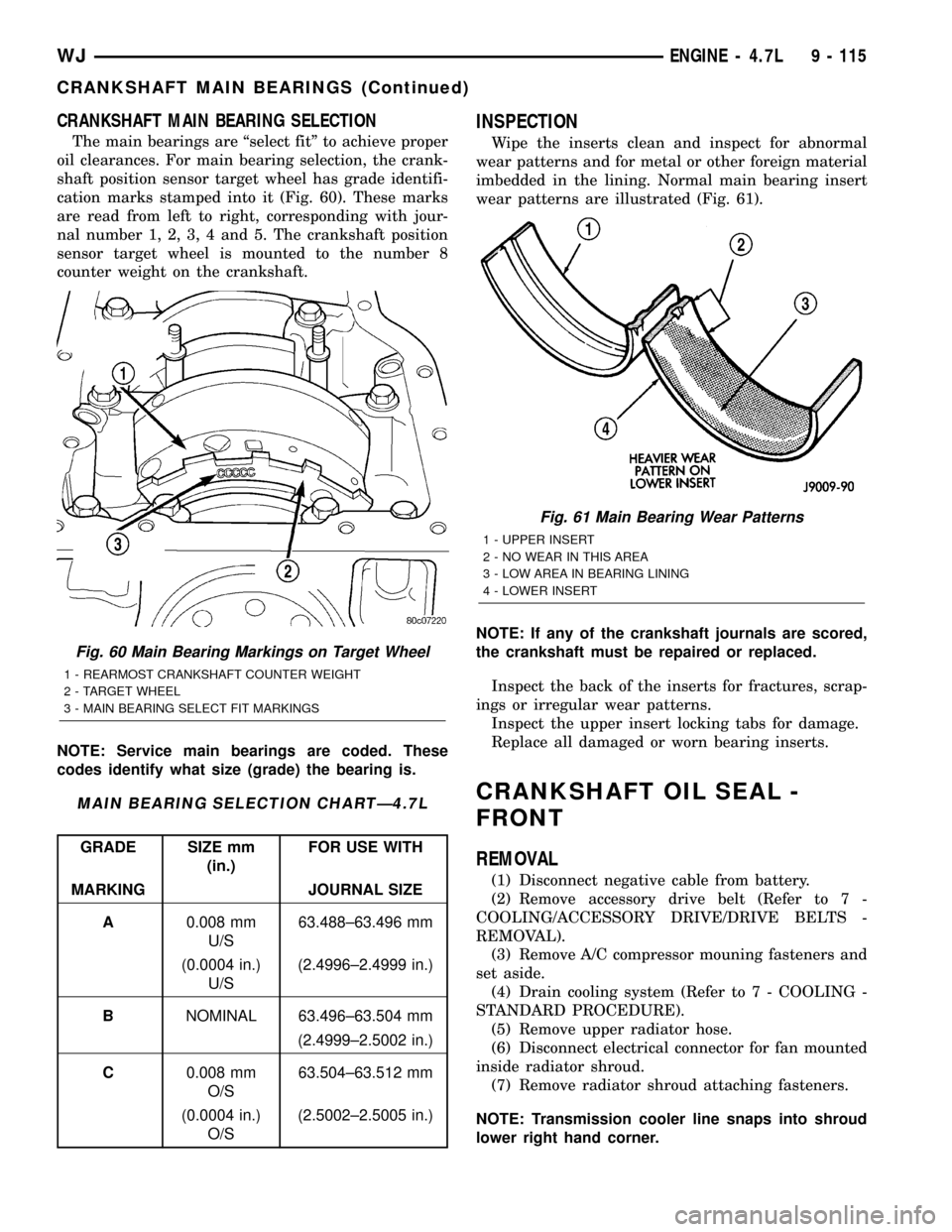
shaft position sensor target wheel has grade identifi-
cation marks stamped into it (Fig. 60). These marks
are read from left to right, corresponding with jour-
nal number 1, 2, 3, 4 and 5. The crankshaft position
sensor target wheel is mounted to the number 8
counter weight on the crankshaft.
NOTE: Service main bearings are coded. These
codes identify what size (grade) the bearing is.
MAIN BEARING SELECTION CHARTÐ4.7L
GRADE SIZE mm
(in.)FOR USE WITH
MARKING JOURNAL SIZE
A0.008 mm
U/S63.488±63.496 mm
(0.0004 in.)
U/S(2.4996±2.4999 in.)
BNOMINAL 63.496±63.504 mm
(2.4999±2.5002 in.)
C0.008 mm
O/S63.504±63.512 mm
(0.0004 in.)
O/S(2.5002±2.5005 in.)
INSPECTION
Wipe the inserts clean and inspect for abnormal
wear patterns and for metal or other foreign material
imbedded in the lining. Normal main bearing insert
wear patterns are illustrated (Fig. 61).
NOTE: If any of the crankshaft journals are scored,
the crankshaft must be repaired or replaced.
Inspect the back of the inserts for fractures, scrap-
ings or irregular wear patterns.
Inspect the upper insert locking tabs for damage.
Replace all damaged or worn bearing inserts.
CRANKSHAFT OIL SEAL -
FRONT
REMOVAL
(1) Disconnect negative cable from battery.
(2) Remove accessory drive belt (Refer to 7 -
COOLING/ACCESSORY DRIVE/DRIVE BELTS -
REMOVAL).
(3) Remove A/C compressor mouning fasteners and
set aside.
(4) Drain cooling system (Refer to 7 - COOLING -
STANDARD PROCEDURE).
(5) Remove upper radiator hose.
(6) Disconnect electrical connector for fan mounted
inside radiator shroud.
(7) Remove radiator shroud attaching fasteners.
NOTE: Transmission cooler line snaps into shroud
lower right hand corner.
Fig. 60 Main Bearing Markings on Target Wheel
1 - REARMOST CRANKSHAFT COUNTER WEIGHT
2 - TARGET WHEEL
3 - MAIN BEARING SELECT FIT MARKINGS
Fig. 61 Main Bearing Wear Patterns
1 - UPPER INSERT
2 - NO WEAR IN THIS AREA
3 - LOW AREA IN BEARING LINING
4 - LOWER INSERT
WJENGINE - 4.7L 9 - 115
CRANKSHAFT MAIN BEARINGS (Continued)
Page 1381 of 2199

(7) Connect throttle cable and speed control cable
to throttle body.
(8) Install fuel rail (Refer to 14 - FUEL SYSTEM/
FUEL DELIVERY/FUEL RAIL - INSTALLATION).
(9) Install ignition coil towers (Refer to 8 - ELEC-
TRICAL/IGNITION CONTROL/IGNITION COIL -
INSTALLATION).
(10) Install coolant temperature sensor (Refer to 7
- COOLING/ENGINE/ENGINE COOLANT TEMP
SENSOR - INSTALLATION).
(11) Connect electrical connectors for the following
components:
²Manifold Absolute Pressure (MAP) Sensor
²Intake Air Temperature (IAT) Sensor
²Throttle Position (TPS) Sensor
²Coolant Temperature (CTS) Sensor
²Idle Air Control (IAC) Motor
²Ignition coil towers
²Fuel injectors
(12) Install top oil dipstick tube retaining bolt and
ground strap.
(13) Install right side engine lifting stud.
(14) Install generator including electrical connec-
tions (Refer to 8 - ELECTRICAL/CHARGING/GEN-
ERATOR - INSTALLATION).
(15) Connect Vapor purge hose, Brake booster
hose, Speed control servo hose, Positive crankcase
ventilation (PCV) hose.
(16) Install air conditioning compressor including
electrical connections.
(17) Fill cooling system (Refer to 7 - COOLING -
STANDARD PROCEDURE).
(18) Install accessory drive belt (Refer to 7 -
COOLING/ACCESSORY DRIVE/DRIVE BELTS -
INSTALLATION).
(19) Install cowl to hood seal (Refer to 23 - BODY/
WEATHERSTRIP/SEALS/COWL WEATHERSTRIP -
INSTALLATION).
(20) Install air cleaner housing and throttle body
resonator. Tighten resonator bolts 4.5 N´m (40 in.
lbs.).
(21) Connect negative cable to battery.
EXHAUST MANIFOLD - LEFT
DESCRIPTION
The exhaust manifolds are log style with a pat-
ented flow enhancing design to maximize perfor-
mance. The exhaust manifolds are made of high
silicon molybdenum cast iron. A perforated core
graphite exhaust manifold gasket is used to improve
sealing to the cylinder head. The exhaust manifolds
are covered by a three layer laminated heat shield
for thermal protection and noise reduction. The heat
shields are fastened with a torque prevailing nutthat is backed off slightly to allow for the thermal
expansion of the exhaust manifold.
REMOVAL
(1) Disconnect negative cable for battery.
(2) Hoist vehicle.
(3) Disconnect exhaust pipe at manifold.
(4) Lower vehicle.
(5) Remove air cleaner housing and tube.
(6) Remove the front two exhaust heat shield
retaining fasteners. Raise vehicle and remove the
fasteners at rear of heat shield.
(7) Remove heat shield (Fig. 107).
(8) Lower vehicle and remove the upper exhaust
manifold retaining bolts (Fig. 107).
(9) Raise vehicle and remove the lower exhaust
manifold retaining bolts (Fig. 107).
(10) Remove exhaust manifold and gasket (Fig.
107). Manifold is removed from below the engine
compartment.
CLEANING
(1) Clean the exhaust manifold using a suitable
cleaning solvent, then allow to air dry.
(2) Clean all gasket residue from the manifold
mating surface.
INSPECTION
(1) Inspect the exhaust manifold for cracks in the
mating surface and at every mounting bolt hole.
(2) Using a straight edge and a feeler gauge, check
the mating surface for warp and twist.
(3) Inspect the manifold to exhaust pipe mating
surface for cracks, gouges, or other damage that
would prevent sealing.
INSTALLATION
(1) Install exhaust manifold and gasket from below
engine compartment.
(2) Install lower exhaust manifold fasteners (Fig.
107). DO NOT tighten until all fasteners are in
place.
(3) Lower vehicle and install upper exhaust mani-
fold fasteners (Fig. 107). Tighten all manifold bolts
starting at center and working outward to 25 N´m
(18 ft. lbs.).
CAUTION: Over tightening heat shield fasteners,
may cause shield to distort and/or crack.
(4) Install exhaust manifold heat shield (Fig. 107).
Tighten fasteners to 8 N´m (72 in. lbs.), then loosen
45 degrees.
(5) Install air cleaner housing and tube.
(6) Connect exhaust pipe to manifold.
(7) Connect negative cable to battery.
9 - 138 ENGINE - 4.7LWJ
INTAKE MANIFOLD (Continued)
Page 1473 of 2199
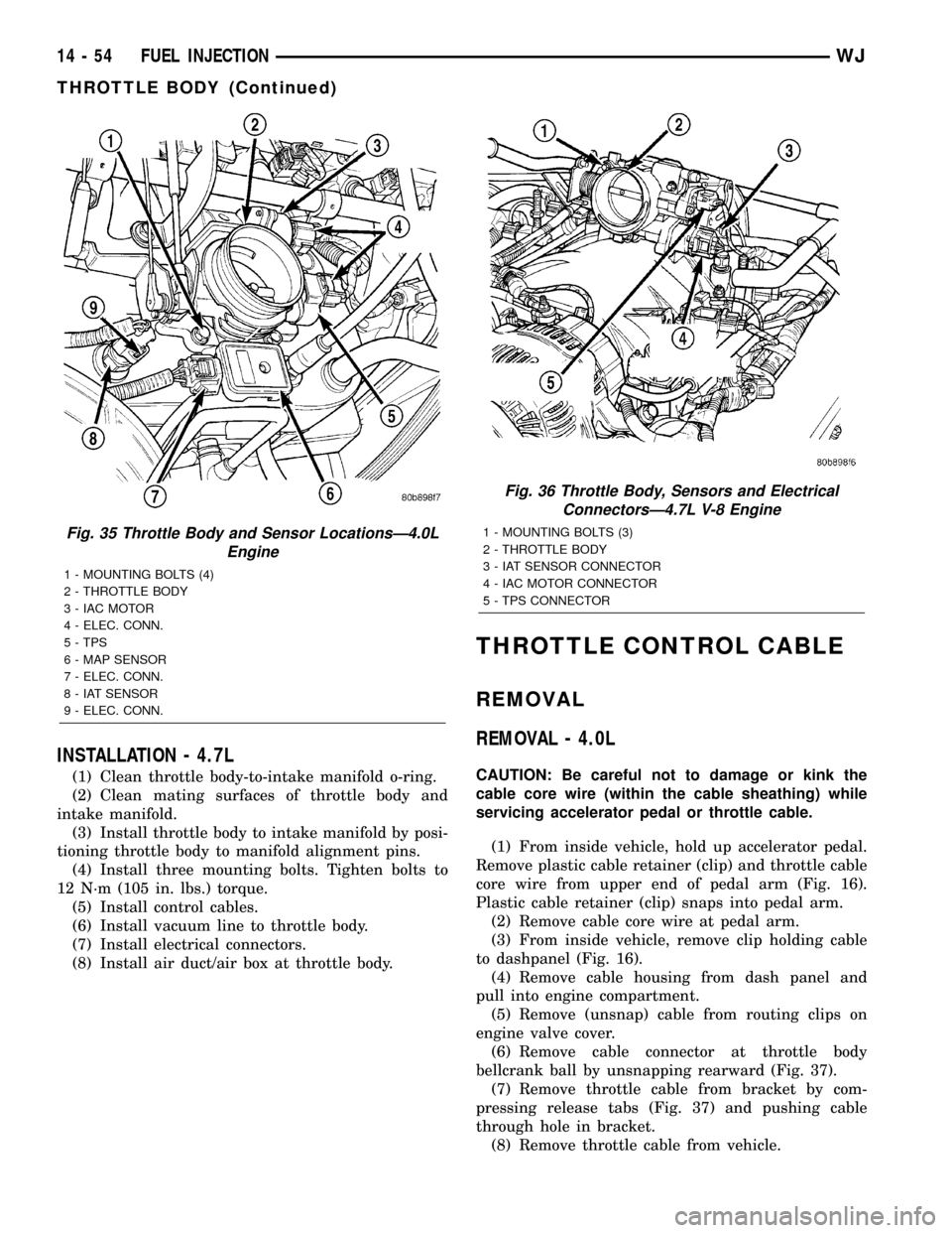
INSTALLATION - 4.7L
(1) Clean throttle body-to-intake manifold o-ring.
(2) Clean mating surfaces of throttle body and
intake manifold.
(3) Install throttle body to intake manifold by posi-
tioning throttle body to manifold alignment pins.
(4) Install three mounting bolts. Tighten bolts to
12 N´m (105 in. lbs.) torque.
(5) Install control cables.
(6) Install vacuum line to throttle body.
(7) Install electrical connectors.
(8) Install air duct/air box at throttle body.
THROTTLE CONTROL CABLE
REMOVAL
REMOVAL - 4.0L
CAUTION: Be careful not to damage or kink the
cable core wire (within the cable sheathing) while
servicing accelerator pedal or throttle cable.
(1) From inside vehicle, hold up accelerator pedal.
Remove plastic cable retainer (clip) and throttle cable
core wire from upper end of pedal arm (Fig. 16).
Plastic cable retainer (clip) snaps into pedal arm.
(2) Remove cable core wire at pedal arm.
(3) From inside vehicle, remove clip holding cable
to dashpanel (Fig. 16).
(4) Remove cable housing from dash panel and
pull into engine compartment.
(5) Remove (unsnap) cable from routing clips on
engine valve cover.
(6) Remove cable connector at throttle body
bellcrank ball by unsnapping rearward (Fig. 37).
(7) Remove throttle cable from bracket by com-
pressing release tabs (Fig. 37) and pushing cable
through hole in bracket.
(8) Remove throttle cable from vehicle.
Fig. 35 Throttle Body and Sensor LocationsÐ4.0L
Engine
1 - MOUNTING BOLTS (4)
2 - THROTTLE BODY
3 - IAC MOTOR
4 - ELEC. CONN.
5 - TPS
6 - MAP SENSOR
7 - ELEC. CONN.
8 - IAT SENSOR
9 - ELEC. CONN.
Fig. 36 Throttle Body, Sensors and Electrical
ConnectorsÐ4.7L V-8 Engine
1 - MOUNTING BOLTS (3)
2 - THROTTLE BODY
3 - IAT SENSOR CONNECTOR
4 - IAC MOTOR CONNECTOR
5 - TPS CONNECTOR
14 - 54 FUEL INJECTIONWJ
THROTTLE BODY (Continued)