2003 JEEP GRAND CHEROKEE Exhaust clamp
[x] Cancel search: Exhaust clampPage 1256 of 2199

INSTALLATION
CAUTION: When installing the engine into a vehicle
equipped with an automatic transmission, be care-
ful not to damage the trigger wheel on the engine
flywheel.
(1) Attach a lifting device to the engine and lower
the engine into the engine compartment. For easier
installation, it may be necessary to remove the
engine mount bracket as an aid in alignment of the
engine to the transmission.
(2) Align the transmission torque converter hous-
ing with the engine.
(3) Loosely install the converter housing lower
bolts and install the next higher bolt and nut on each
side.
(4) Tighten all 4 bolts finger tight.
(5) Install the engine mount brackets (if removed).
(6) Lower the engine and engine mount brackets
onto the engine compartment cushions. Install the
bolts and finger tighten the nuts.
(7) Remove the engine lifting device.
(8) Raise and support the vehicle.
(9) Install the remaining engine flywheel/converter
housing bolts. Tighten all bolts to 38 N´m (28 ft. lbs.)
torque.
(10) Install the converter-to-drive plate bolts.
(11) Ensure the installation reference marks are
aligned.
(12) Install the engine flywheel/converter housing
access cover.
(13) Install the exhaust pipe support and tighten
the screw.
(14) Install the engine bending brace (Refer to 9 -
ENGINE/ENGINE BLOCK/STRUCT SUPPORT -
INSTALLATION).
(15) Tighten the engine mount-to-bracket bolts.
(16) Connect the vehicle speed sensor wire connec-
tions and tighten the screws.
(17) Connect the exhaust pipe to the manifold.
(18) Install the engine starter motor (Refer to 8 -
ELECTRICAL/STARTING/STARTER MOTOR -
INSTALLATION).
(19) Connect the wires to the engine starter motor
solenoid.
(20) Lower the vehicle.
(21) Connect all the vacuum hoses and wire con-
nectors identified during engine removal.
(22) Remove protective caps from the power steer-
ing hoses.
(23) Connect the hoses to the fittings at the steer-
ing gear. Tighten the nut to 52 N´m (38 ft. lbs.)
torque.
(24) Fill the pump reservoir with fluid.(25) Inspect the fuel supply line o-ring(s) and
replace if necessary. Connect fuel supply line to injec-
tior rail and verify connection by pulling outward on
the line.
(26) Install the fuel line bracket to the intake
manifold.
(27) Connect the coil rail electrical connectors and
oil pressure switch connector.
(28) Connect the following electrical connectors:
²Power steering pressure switch
²Coolant temperature sensor
²Six (6) fuel injector connectors
²Intake air temperature sensor
²Throttle position sensor
²Map sensor
²Crankshaft position sensor
²Oxygen sensor
²Camshaft position sensor
²Generator connector and B+ terminal wire
(29) Connect all previously removed vacuum hoses.
(30) Connect the body ground strap.
(31) Install the throttle, transmission line pres-
sure, and speed control cables to their mounting
bracket and connect them to the throttle body.
(32) Connect the heater hoses at the engine ther-
mostat housing and water pump.
(33) Install the fan assembly (Refer to 7 - COOL-
ING/ENGINE/RADIATOR FAN - INSTALLATION).
(34) Place the fan shroud in position over the fan.
(35) Install the radiator (Refer to 7 - COOLING/
ENGINE/RADIATOR - INSTALLATION).
(36) Connect the service valves to the A/C com-
pressor ports, if equipped with A/C.
(37) Charge the air conditioner system (Refer to 24
- HEATING & AIR CONDITIONING/PLUMBING -
STANDARD PROCEDURE).
(38) Connect the radiator hoses and automatic
transmission fluid cooler pipes, if equipped.
(39) Install the fan shroud to the radiator or radi-
ator/condenser (if equipped with A/C).
(40) Install upper radiator support.
(41) Connect the upper radiator hose and tighten
the clamp.
(42) Connect the lower radiator hose and tighten
the clamp.
(43) Fill crankcase with engine oil. (Refer to
LUBRICATION & MAINTENANCE/FLUID CAPACI-
TIES - SPECIFICATIONS) for correct capacities.
(44) Fill the cooling system with reusable coolant
or new coolant (Refer to 7 - COOLING - STANDARD
PROCEDURE).
(45) Align the hood to the scribe marks. Install the
hood.
(46) Install the air cleaner assembly.
(47) Install the battery and connect the battery
cable.
WJENGINE - 4.0L 9 - 13
ENGINE - 4.0L (Continued)
Page 1261 of 2199

DESCRIPTION N´m Ft. In.
Lbs. Lbs.
Transmission Support Bracket
ÐBolt (Manual) 46 34 Ð
Transmission Support Bracket/
CushionÐBolt (4WD Auto) 75 55 Ð
Transmission Support Adaptor
BracketÐBolts (2WD Auto) 75 55 Ð
Exhaust Manifold/PipeÐNuts 27 20 Ð
Intake/Exhaust Manifold
Fasteners #1-5 33 24 Ð
Fasteners #6 and 7 14 Ð 126
Fasteners #8-11 33 24 Ð
Flywheel to Converter
HousingÐBolts38 28 Ð
Flywheel to CrankshaftÐBolts 143 105 Ð
Front Cover to BlockÐBolts
1/4-20 7 Ð 60
5/16-18 22 Ð 192
Fuel RailÐBolts/Stud 12 Ð 108
GeneratorÐBolts 57 42 Ð
Generator Bracket to EngineÐ
Bolts47 35 Ð
Idler Pulley to Cylinder
HeadÐBolt47 35 Ð
Main Bearing CapÐBolts 108 80 Ð
Oil Filter 18 Ð 156
Oil Filter Connector to
Adaptor 47 35 Ð
Block 68 50 Ð
Adaptor Bolts 102 50 Ð
Oil GalleyÐPlug 41 30 Ð
Oil PanÐBolts
1/4-20 9.5 Ð 84
5/16-18 15 Ð 132
Oil PanÐDrain Plug 34 25 Ð
Oil Pump
Mounting Bolts 23 Ð 204
Cover Bolts 8 Ð 70
Rocker Arm Assembly to
Cylinder
HeadÐCapscrews 30 21 Ð
Spark Plugs 37 27 ÐDESCRIPTION N´m Ft. In.
Lbs. Lbs.
Starter MotorÐMounting Bolts 45 33 Ð
Thermostat HousingÐBolts 18 Ð 156
Throttle BodyÐBolts 10 Ð 90
Vibration DamperÐBolt 108 80 Ð
Water Pump to BlockÐBolts 23 17 Ð
AIR CLEANER ELEMENT
REMOVAL - 4.0L
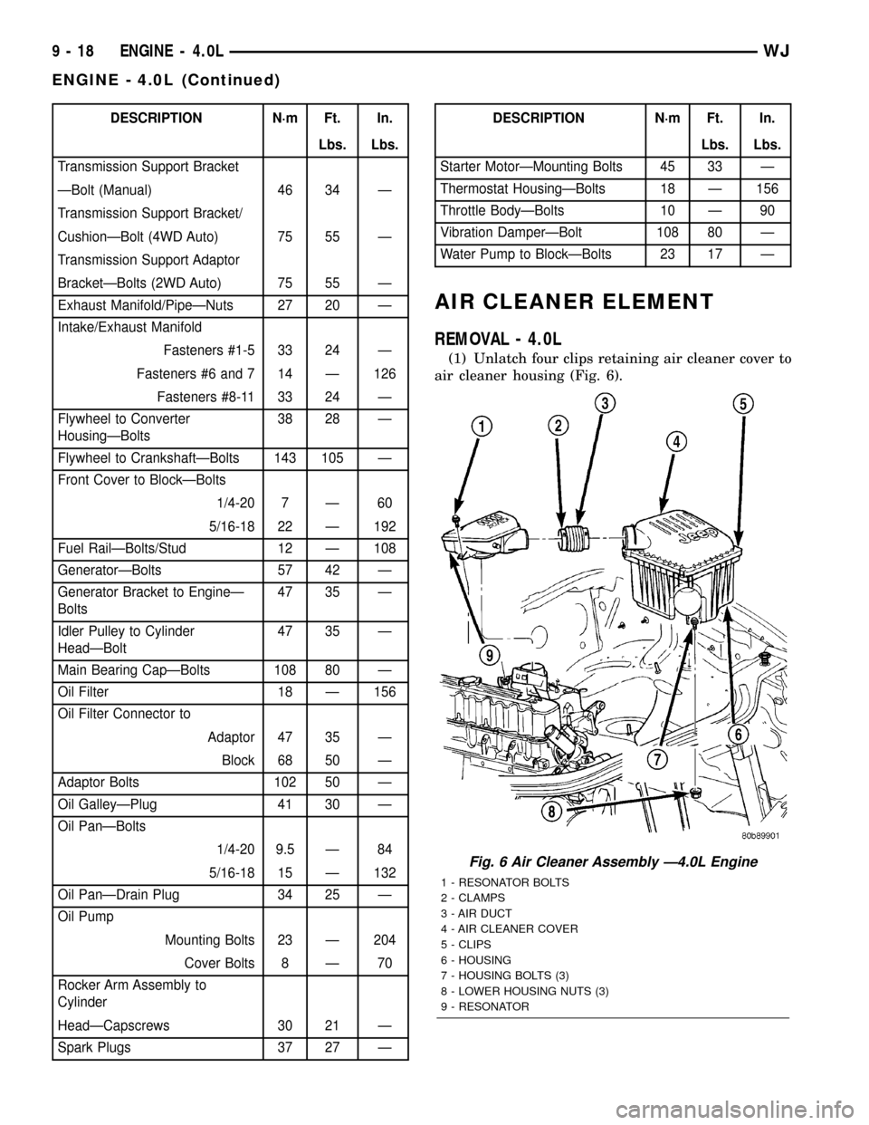
(1) Unlatch four clips retaining air cleaner cover to
air cleaner housing (Fig. 6).
Fig. 6 Air Cleaner Assembly Ð4.0L Engine
1 - RESONATOR BOLTS
2 - CLAMPS
3 - AIR DUCT
4 - AIR CLEANER COVER
5 - CLIPS
6 - HOUSING
7 - HOUSING BOLTS (3)
8 - LOWER HOUSING NUTS (3)
9 - RESONATOR
9 - 18 ENGINE - 4.0LWJ
ENGINE - 4.0L (Continued)
Page 1400 of 2199

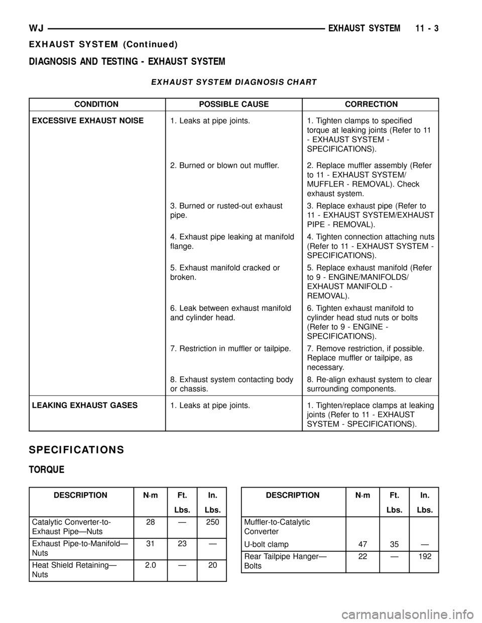
DIAGNOSIS AND TESTING - EXHAUST SYSTEM
EXHAUST SYSTEM DIAGNOSIS CHART
CONDITION POSSIBLE CAUSE CORRECTION
EXCESSIVE EXHAUST NOISE1. Leaks at pipe joints. 1. Tighten clamps to specified
torque at leaking joints (Refer to 11
- EXHAUST SYSTEM -
SPECIFICATIONS).
2. Burned or blown out muffler. 2. Replace muffler assembly (Refer
to 11 - EXHAUST SYSTEM/
MUFFLER - REMOVAL). Check
exhaust system.
3. Burned or rusted-out exhaust
pipe.3. Replace exhaust pipe (Refer to
11 - EXHAUST SYSTEM/EXHAUST
PIPE - REMOVAL).
4. Exhaust pipe leaking at manifold
flange.4. Tighten connection attaching nuts
(Refer to 11 - EXHAUST SYSTEM -
SPECIFICATIONS).
5. Exhaust manifold cracked or
broken.5. Replace exhaust manifold (Refer
to 9 - ENGINE/MANIFOLDS/
EXHAUST MANIFOLD -
REMOVAL).
6. Leak between exhaust manifold
and cylinder head.6. Tighten exhaust manifold to
cylinder head stud nuts or bolts
(Refer to 9 - ENGINE -
SPECIFICATIONS).
7. Restriction in muffler or tailpipe. 7. Remove restriction, if possible.
Replace muffler or tailpipe, as
necessary.
8. Exhaust system contacting body
or chassis.8. Re-align exhaust system to clear
surrounding components.
LEAKING EXHAUST GASES1. Leaks at pipe joints. 1. Tighten/replace clamps at leaking
joints (Refer to 11 - EXHAUST
SYSTEM - SPECIFICATIONS).
SPECIFICATIONS
TORQUE
DESCRIPTION N´m Ft. In.
Lbs. Lbs.
Catalytic Converter-to-
Exhaust PipeÐNuts28 Ð 250
Exhaust Pipe-to-ManifoldÐ
Nuts31 23 Ð
Heat Shield RetainingÐ
Nuts2.0 Ð 20DESCRIPTION N´m Ft. In.
Lbs. Lbs.
Muffler-to-Catalytic
Converter
U-bolt clamp 47 35 Ð
Rear Tailpipe HangerÐ
Bolts22 Ð 192
WJEXHAUST SYSTEM 11 - 3
EXHAUST SYSTEM (Continued)
Page 1402 of 2199

(1) Raise and support the vehicle.
(2) Saturate the bolts and nuts with heat valve
lubricant. Allow 5 minutes for penetration.
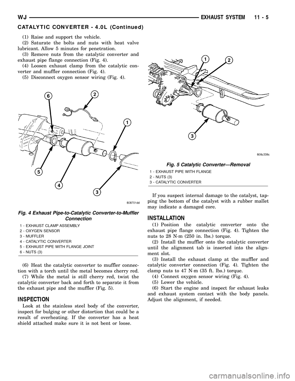
(3) Remove nuts from the catalytic converter and
exhaust pipe flange connection (Fig. 4).
(4) Loosen exhaust clamp from the catalytic con-
verter and muffler connection (Fig. 4).
(5) Disconnect oxygen sensor wiring (Fig. 4).
(6) Heat the catalytic converter to muffler connec-
tion with a torch until the metal becomes cherry red.
(7) While the metal is still cherry red, twist the
catalytic converter back and forth to separate it from
the exhaust pipe and the muffler (Fig. 5).
INSPECTION
Look at the stainless steel body of the converter,
inspect for bulging or other distortion that could be a
result of overheating. If the converter has a heat
shield attached make sure it is not bent or loose.If you suspect internal damage to the catalyst, tap-
ping the bottom of the catalyst with a rubber mallet
may indicate a damaged core.
INSTALLATION
(1) Position the catalytic converter onto the
exhaust pipe flange connection (Fig. 4). Tighten the
nuts to 28 N´m (250 in. lbs.) torque.
(2) Install the muffler onto the catalytic converter
until the alignment tab is inserted into the align-
ment slot.
(3) Install the exhaust clamp at the muffler and
catalytic converter connection (Fig. 4). Tighten the
clamp nuts to 47 N´m (35 ft. lbs.) torque.
(4) Connect oxygen sensor wiring (Fig. 4).
(5) Lower the vehicle.
(6) Start the engine and inspect for exhaust leaks
and exhaust system contact with the body panels.
Adjust the alignment, if needed.
Fig. 4 Exhaust Pipe-to-Catalytic Converter-to-Muffler
Connection
1 - EXHAUST CLAMP ASSEMBLY
2 - OXYGEN SENSOR
3 - MUFFLER
4 - CATALYTIC CONVERTER
5 - EXHAUST PIPE WITH FLANGE JOINT
6 - NUTS (3)
Fig. 5 Catalytic ConverterÐRemoval
1 - EXHAUST PIPE WITH FLANGE
2 - NUTS (3)
3 - CATALYTIC CONVERTER
WJEXHAUST SYSTEM 11 - 5
CATALYTIC CONVERTER - 4.0L (Continued)
Page 1404 of 2199

(1) Raise and support the vehicle.
(2) Saturate the bolts and nuts with heat valve
lubricant. Allow 5 minutes for penetration.
(3) Remove nuts from the catalytic converter and
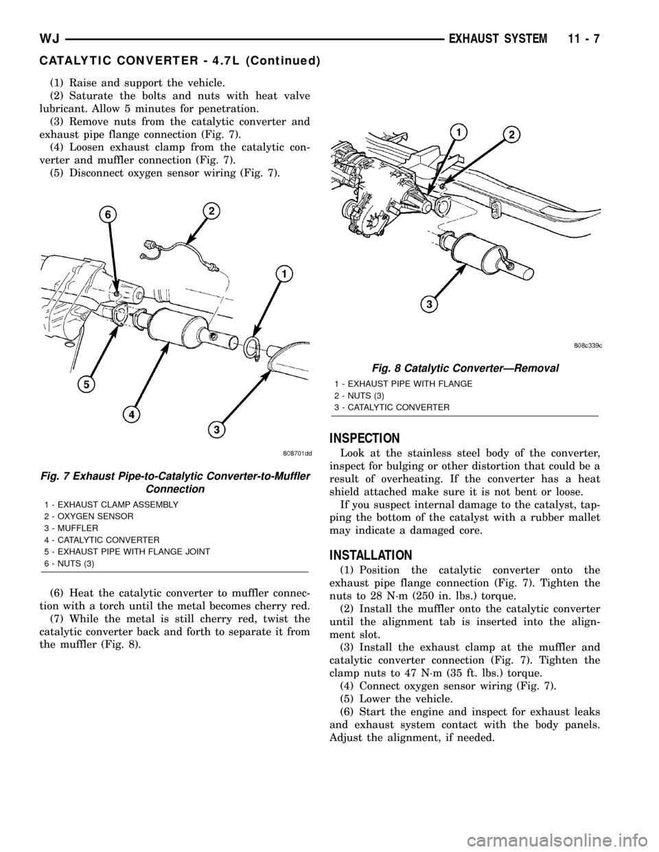
exhaust pipe flange connection (Fig. 7).
(4) Loosen exhaust clamp from the catalytic con-
verter and muffler connection (Fig. 7).
(5) Disconnect oxygen sensor wiring (Fig. 7).
(6) Heat the catalytic converter to muffler connec-
tion with a torch until the metal becomes cherry red.
(7) While the metal is still cherry red, twist the
catalytic converter back and forth to separate it from
the muffler (Fig. 8).
INSPECTION
Look at the stainless steel body of the converter,
inspect for bulging or other distortion that could be a
result of overheating. If the converter has a heat
shield attached make sure it is not bent or loose.
If you suspect internal damage to the catalyst, tap-
ping the bottom of the catalyst with a rubber mallet
may indicate a damaged core.
INSTALLATION
(1) Position the catalytic converter onto the
exhaust pipe flange connection (Fig. 7). Tighten the
nuts to 28 N´m (250 in. lbs.) torque.
(2) Install the muffler onto the catalytic converter
until the alignment tab is inserted into the align-
ment slot.
(3) Install the exhaust clamp at the muffler and
catalytic converter connection (Fig. 7). Tighten the
clamp nuts to 47 N´m (35 ft. lbs.) torque.
(4) Connect oxygen sensor wiring (Fig. 7).
(5) Lower the vehicle.
(6) Start the engine and inspect for exhaust leaks
and exhaust system contact with the body panels.
Adjust the alignment, if needed.
Fig. 7 Exhaust Pipe-to-Catalytic Converter-to-Muffler
Connection
1 - EXHAUST CLAMP ASSEMBLY
2 - OXYGEN SENSOR
3 - MUFFLER
4 - CATALYTIC CONVERTER
5 - EXHAUST PIPE WITH FLANGE JOINT
6 - NUTS (3)
Fig. 8 Catalytic ConverterÐRemoval
1 - EXHAUST PIPE WITH FLANGE
2 - NUTS (3)
3 - CATALYTIC CONVERTER
WJEXHAUST SYSTEM 11 - 7
CATALYTIC CONVERTER - 4.7L (Continued)
Page 1405 of 2199

EXHAUST PIPE - 4.0L
REMOVAL
WARNING: IF TORCHES ARE USED WHEN WORK-
ING ON THE EXHAUST SYSTEM, DO NOT ALLOW
THE FLAME NEAR THE FUEL LINES.
WARNING: THE NORMAL OPERATING TEMPERA-
TURE OF THE EXHAUST SYSTEM IS VERY HIGH.
THEREFORE, NEVER WORK AROUND OR ATTEMPT
TO SERVICE ANY PART OF THE EXHAUST SYSTEM
UNTIL IT IS COOLED. SPECIAL CARE SHOULD BE
TAKEN WHEN WORKING NEAR THE CATALYTIC
CONVERTER. THE TEMPERATURE OF THE CON-
VERTER RISES TO A HIGH LEVEL AFTER A SHORT
PERIOD OF ENGINE OPERATION TIME.
(1) Raise and support the vehicle.(2) Saturate the bolts and nuts with heat valve
lubricant. Allow 5 minutes for penetration.
(3) Remove the oxygen sensor from the exhaust
pipe (Fig. 9).
(4) Remove the nuts from the exhaust pipe to cat-
alytic converter flange connection (Fig. 10).
(5) Disconnect the exhaust pipe from the exhaust
manifold (Fig. 11).
INSPECTION
Discard rusted clamps, broken or worn supports
and attaching parts. Replace a component with orig-
inal equipment parts, or equivalent. This will assure
proper alignment with other parts in the system and
provide acceptable exhaust noise levels.
INSTALLATION
(1) Connect the exhaust pipe to the engine exhaust
manifold. Tighten the nuts to 31 N´m (23 ft. lbs.)
(Fig. 11).
Fig. 9 O2 Sensor Location 4.0L
11 - 8 EXHAUST SYSTEMWJ
Page 1406 of 2199

NOTE: When servicing the exhaust system, replace
the factory installed uni-clamp with standard u-bolt
clamps.
(2) Position the catalytic converter onto the
exhaust pipe flange connection. Tighten retaining
nuts to 28 N´m (250 in. lbs.) (Fig. 12).
(3) Coat the oxygen sensor with anti-seize com-
pound. Install the sensor and tighten the nut to 48
N´m (35 ft. lbs.) torque (Fig. 9).
(4) Lower the vehicle.
(5) Start the engine and inspect for exhaust leaks
and exhaust system contact with the body panels.
Adjust the alignment, if needed.
(6) After initial start-up, check the engine exhaust
manifold to exhaust pipe nuts for proper torque.
Fig. 10 Catalytic ConverterÐRemoval
1 - EXHAUST PIPE WITH FLANGE
2 - NUTS (3)
3 - CATALYTIC CONVERTER
Fig. 11 Exhaust Pipe 4.0L
1 - NUT
2 - EXHAUST MANIFOLD
3 - TRANSMISSION SUPPORT
4 - EXHAUST PIPE
5 - MINI CATALYTIC CONVERTER
6 - BOLT
Fig. 12 Installing Exhaust Clamps
1 - CATALYTIC CONVERTER
2 - MUFFLER
WJEXHAUST SYSTEM 11 - 9
EXHAUST PIPE - 4.0L (Continued)
Page 1407 of 2199

EXHAUST PIPE - 4.7L
REMOVAL
WARNING: IF TORCHES ARE USED WHEN WORK-
ING ON THE EXHAUST SYSTEM, DO NOT ALLOW
THE FLAME NEAR THE FUEL LINES.
WARNING: THE NORMAL OPERATING TEMPERA-
TURE OF THE EXHAUST SYSTEM IS VERY HIGH.
THEREFORE, NEVER WORK AROUND OR ATTEMPT
TO SERVICE ANY PART OF THE EXHAUST SYSTEM
UNTIL IT IS COOLED. SPECIAL CARE SHOULD BE
TAKEN WHEN WORKING NEAR THE CATALYTIC
CONVERTER. THE TEMPERATURE OF THE CON-
VERTER RISES TO A HIGH LEVEL AFTER A SHORT
PERIOD OF ENGINE OPERATION TIME.
(1) Raise and support the vehicle.(2) Saturate the bolts and nuts with heat valve
lubricant. Allow 5 minutes for penetration.
(3) Remove the oxygen sensor from the exhaust
pipe (Fig. 13).
(4) Remove the retaining nuts holding catalytic
converter to exhaust pipe (Fig. 14).
(5) Disconnect the exhaust pipe from the exhaust
manifold. (Fig. 15)
INSPECTION
Discard rusted clamps, broken or worn supports
and attaching parts. Replace a component with orig-
inal equipment parts, or equivalent. This will assure
proper alignment with other parts in the system and
provide acceptable exhaust noise levels.
INSTALLATION
(1) Connect the exhaust pipe to the engine exhaust
manifold. Tighten the nuts (A) to 31 N´m (23 ft. lbs.)
(Fig. 15).
Fig. 13 4.7L Catalytic Converter and O2 Sensor Configuration - 50 State Emissions
11 - 10 EXHAUST SYSTEMWJ