2003 JEEP GRAND CHEROKEE transmission crossmember
[x] Cancel search: transmission crossmemberPage 1561 of 2199

(11) Move transmission forward. Then raise, lower
or tilt transmission to align converter housing with
engine block dowels.
(12) Carefully work transmission forward and over
engine block dowels until converter hub is seated in
crankshaft.
(13) Install two bolts to attach converter housing
to engine.
(14) Install the upper transmission bending braces
to the torque converter housing and the overdrive
unit. Tighten the bolts to 41 N´m (30 ft.lbs.).
(15) Install remaining torque converter housing to
engine bolts. Tighten to 68 N´m (50 ft.lbs.).
(16) Install rear transmission crossmember.
Tighten crossmember to frame bolts to 68 N´m (50
ft.lbs.).
(17) Install rear support to transmission. Tighten
bolts to 47 N´m (35 ft.lbs.).
(18) Lower transmission onto crossmember and
install bolts attaching transmission mount to cross-
member. Tighten clevis bracket to crossmember bolts
to 47 N´m (35 ft.lbs.). Tighten the clevis bracket to
rear support bolt to 68 N´m (50 ft.lbs.).
(19) Remove engine support fixture.
(20) Install crankshaft position sensor. (Refer to 14
- FUEL SYSTEM/FUEL INJECTION/CRANKSHAFT
POSITION SENSOR - INSTALLATION)
(21) Install new plastic retainer grommet on any
shift cable that was disconnected. Grommets should
not be reused. Use pry tool to remove rod from grom-
met and cut away old grommet. Use pliers to snap
new grommet into cable and to snap grommet onto
lever.
(22) Connect gearshift and throttle valve cable to
transmission.
(23) Connect wires to park/neutral position switch
and transmission solenoid connector. Be sure trans-
mission harnesses are properly routed.CAUTION: It is essential that correct length bolts be
used to attach the converter to the driveplate. Bolts
that are too long will damage the clutch surface
inside the converter.
(24) Install all torque converter-to-driveplate bolts
by hand.
(25) Verify that the torque converter is pulled
flush to the driveplate. Tighten bolts to 31 N´m (270
in. lbs.).
(26) Install converter housing access cover. Tighten
bolt to 23 N´m (200 in.lbs.).
(27) Install the bell housing brace to the torque
converter cover and the engine to transmission bend-
ing brace. Tighten the bolts and nut to 41 N´m (30
ft.lbs.).
(28) Install starter motor (Refer to 8 - ELECTRI-
CAL/STARTING/STARTER MOTOR - INSTALLA-
TION) and cooler line bracket.
(29) Connect cooler lines to transmission.
(30) Install transmission fill tube. Install new seal
on tube before installation.
(31) Install exhaust components.
(32) Install transfer case. Tighten transfer case
nuts to 35 N´m (26 ft.lbs.).
(33) Install the transfer case shift cable to the
cable support bracket and the transfer case shift
lever.
(34) Align and connect propeller shaft(s).
(35) Adjust gearshift linkage and throttle valve
cable if necessary.
(36) Lower vehicle.
(37) Fill transmission with MopartATF +4, type
9602, fluid.
21 - 42 AUTOMATIC TRANSMISSION - 42REWJ
AUTOMATIC TRANSMISSION - 42RE (Continued)
Page 1575 of 2199

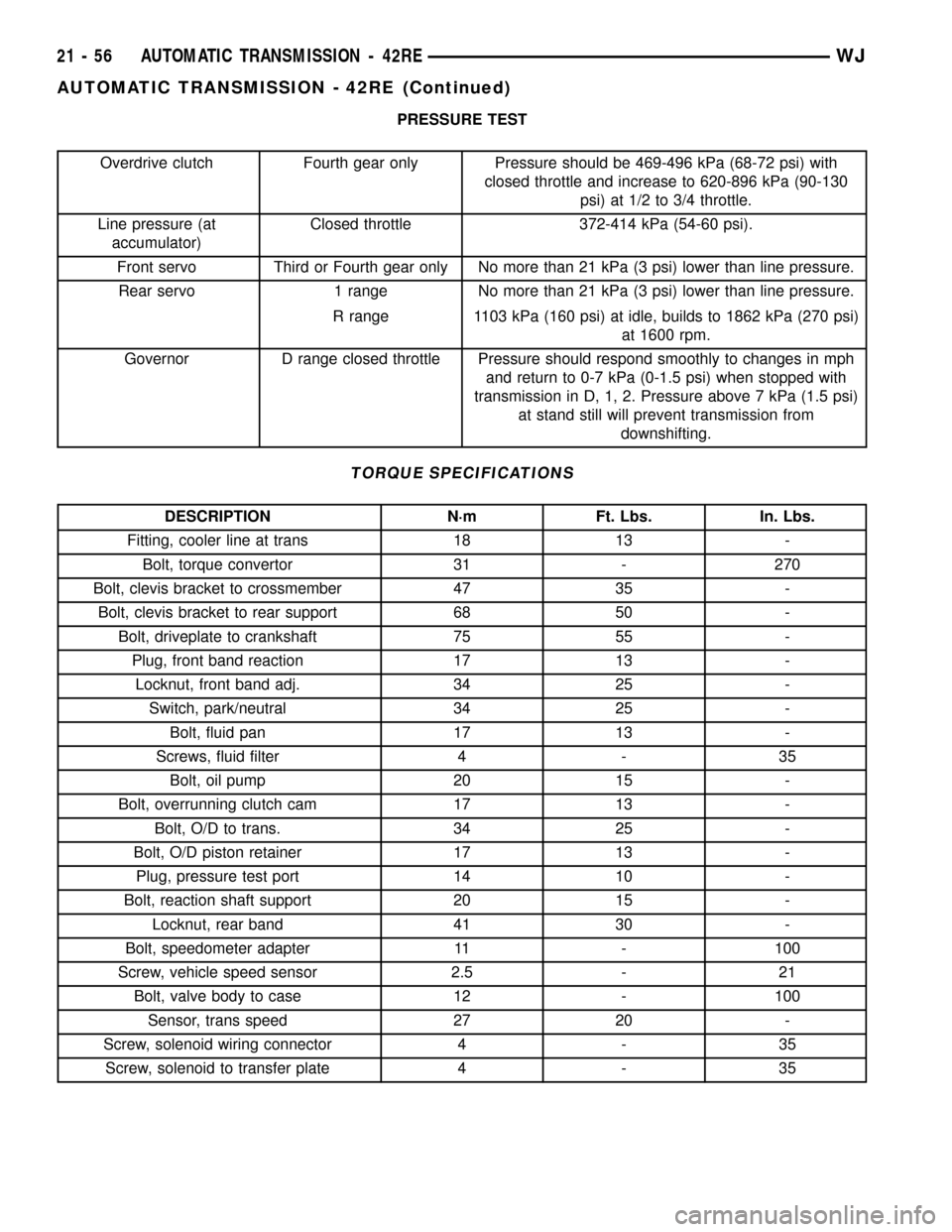
PRESSURE TEST
Overdrive clutch Fourth gear only Pressure should be 469-496 kPa (68-72 psi) with
closed throttle and increase to 620-896 kPa (90-130
psi) at 1/2 to 3/4 throttle.
Line pressure (at
accumulator)Closed throttle 372-414 kPa (54-60 psi).
Front servo Third or Fourth gear only No more than 21 kPa (3 psi) lower than line pressure.
Rear servo 1 range No more than 21 kPa (3 psi) lower than line pressure.
R range 1103 kPa (160 psi) at idle, builds to 1862 kPa (270 psi)
at 1600 rpm.
Governor D range closed throttle Pressure should respond smoothly to changes in mph
and return to 0-7 kPa (0-1.5 psi) when stopped with
transmission in D, 1, 2. Pressure above 7 kPa (1.5 psi)
at stand still will prevent transmission from
downshifting.
TORQUE SPECIFICATIONS
DESCRIPTION N´m Ft. Lbs. In. Lbs.
Fitting, cooler line at trans 18 13 -
Bolt, torque convertor 31 - 270
Bolt, clevis bracket to crossmember 47 35 -
Bolt, clevis bracket to rear support 68 50 -
Bolt, driveplate to crankshaft 75 55 -
Plug, front band reaction 17 13 -
Locknut, front band adj. 34 25 -
Switch, park/neutral 34 25 -
Bolt, fluid pan 17 13 -
Screws, fluid filter 4 - 35
Bolt, oil pump 20 15 -
Bolt, overrunning clutch cam 17 13 -
Bolt, O/D to trans. 34 25 -
Bolt, O/D piston retainer 17 13 -
Plug, pressure test port 14 10 -
Bolt, reaction shaft support 20 15 -
Locknut, rear band 41 30 -
Bolt, speedometer adapter 11 - 100
Screw, vehicle speed sensor 2.5 - 21
Bolt, valve body to case 12 - 100
Sensor, trans speed 27 20 -
Screw, solenoid wiring connector 4 - 35
Screw, solenoid to transfer plate 4 - 35
21 - 56 AUTOMATIC TRANSMISSION - 42REWJ
AUTOMATIC TRANSMISSION - 42RE (Continued)
Page 1703 of 2199

(12) Disconnect gearshift cable from transmission
manual valve lever (Fig. 9).
(13) Disconnect transfer case shift cable from the
transfer case shift lever (Fig. 10).
(14) Remove the clip securing the transfer case
shift cable into the cable support bracket.
(15) Disconnect transmission fluid cooler lines at
transmission fittings and clips.
(16) Disconnect the transmission vent hose from
the transmission.
(17) Support rear of engine with safety stand or
jack.
(18) Raise transmission slightly with service jack
to relieve load on crossmember and supports.(19) Remove bolts securing rear support and cush-
ion to transmission and crossmember (Fig. 11).
(20) Remove bolts attaching crossmember to frame
and remove crossmember.
(21) Remove transfer case (Fig. 12) and (Fig. 13).
(22) Remove all remaining converter housing bolts.
(23) Carefully work transmission and torque con-
verter assembly rearward off engine block dowels.
(24) Hold torque converter in place during trans-
mission removal.
(25) Lower transmission and remove assembly
from under the vehicle.
Fig. 9 Transmission Shift Cable
1 - SHIFT CABLE
2 - MANUAL LEVER
3 - MANUAL LEVER
Fig. 10 Transfer Case Shift Cable
1 - TRANSFER CASE SHIFT LEVER
2 - TRANSFER CASE SHIFT CABLE
Fig. 11 Rear Transmission Crossmember
1 - CROSSMEMBER
2 - REAR TRANSMISSION MOUNT
Fig. 12 Remove NV247 Transfer Case
1 - NV247 TRANSFER CASE
21 - 184 AUTOMATIC TRANSMISSION - 545RFEWJ
AUTOMATIC TRANSMISSION - 545RFE (Continued)
Page 1717 of 2199

(5) Carefully insert converter in oil pump. Then
rotate converter back and forth until fully seated in
pump gears.
(6) Check converter seating with steel scale and
straightedge (Fig. 52). Surface of converter lugs
should be at least 13 mm (1/2 in.) to rear of straight-
edge when converter is fully seated.
(7) Temporarily secure converter with C-clamp.
(8) Position transmission on jack and secure it
with chains.
(9) Check condition of converter driveplate.
Replace the plate if cracked, distorted or damaged.
Also be sure transmission dowel pins are seated
in engine block and protrude far enough to
hold transmission in alignment.
(10) Apply a light coating of MopartHigh Temp
Grease to the torque converter hub pocket in the rear
pocket of the engine's crankshaft.
(11) Raise transmission and align the torque con-
verter with the drive plate and the transmission con-
verter housing with the engine block.
(12) Move transmission forward. Then raise, lower,
or tilt transmission to align the converter housing
with the engine block dowels.
(13) Carefully work transmission forward and over
engine block dowels until converter hub is seated in
crankshaft. Verify that no wires, or the transmission
vent hose, have become trapped between the engine
block and the transmission.
(14) Install two bolts to attach the transmission to
the engine.(15) Install remaining torque converter housing to
engine bolts. Tighten to 68 N´m (50 ft.lbs.).
(16) Install rear transmission crossmember.
Tighten crossmember to frame bolts to 68 N´m (50
ft.lbs.).
(17) Install rear support to transmission. Tighten
bolts to 47 N´m (35 ft.lbs.).
(18) Lower transmission onto crossmember and
install bolts attaching transmission mount to cross-
member. Tighten clevis bracket to crossmember bolts
to 47 N´m (35 ft.lbs.). Tighten the clevis bracket to
rear support bolt to 68 N´m (50 ft.lbs.).
(19) Remove engine support fixture.
(20) Install new plastic retainer grommet on any
shift cable that was disconnected. Grommets should
not be reused. Use pry tool to remove rod from grom-
met and cut away old grommet. Use pliers to snap
new grommet into cable and to snap grommet onto
lever.
(21) Connect gearshift cable to transmission.
(22) Connect wires to solenoid and pressure switch
assembly connector, input and output speed sensors,
and line pressure sensor. Be sure transmission har-
nesses are properly routed.
CAUTION: It is essential that correct length bolts be
used to attach the converter to the driveplate. Bolts
that are too long will damage the clutch surface
inside the converter.
(23) Install all torque converter-to-driveplate bolts
by hand.
(24) Verify that the torque converter is pulled
flush to the driveplate. Tighten bolts to 31 N´m (270
in. lbs.).
(25) Install starter motor and cooler line bracket.
(26) Connect cooler lines to transmission.
(27) Install transmission fill tube.
(28) Install exhaust components.
(29) Install transfer case. Tighten transfer case
nuts to 35 N´m (26 ft.lbs.).
(30) Install the transfer case shift cable to the
cable support bracket and the transfer case shift
lever.
(31) Install the transmission collar onto the trans-
mission and the engine. Tighten the bolts to 54 N´m
(40 ft.lbs.).
(32) Align and connect propeller shaft(s).
(33) Adjust gearshift cable if necessary.
(34) Lower vehicle.
(35) Fill transmission with MopartATF +4, type
9602, Automatic Transmission fluid.
Fig. 52 Checking Torque Converter Seating - Typical
1 - SCALE
2 - STRAIGHTEDGE
21 - 198 AUTOMATIC TRANSMISSION - 545RFEWJ
AUTOMATIC TRANSMISSION - 545RFE (Continued)
Page 1739 of 2199

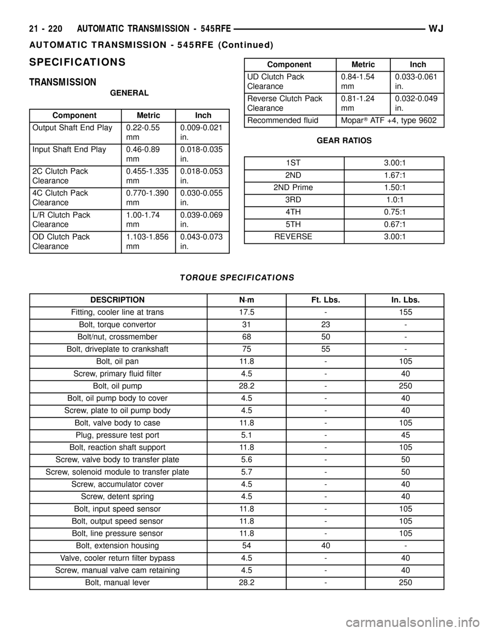
SPECIFICATIONS
TRANSMISSION
GENERAL
Component Metric Inch
Output Shaft End Play 0.22-0.55
mm0.009-0.021
in.
Input Shaft End Play 0.46-0.89
mm0.018-0.035
in.
2C Clutch Pack
Clearance0.455-1.335
mm0.018-0.053
in.
4C Clutch Pack
Clearance0.770-1.390
mm0.030-0.055
in.
L/R Clutch Pack
Clearance1.00-1.74
mm0.039-0.069
in.
OD Clutch Pack
Clearance1.103-1.856
mm0.043-0.073
in.
Component Metric Inch
UD Clutch Pack
Clearance0.84-1.54
mm0.033-0.061
in.
Reverse Clutch Pack
Clearance0.81-1.24
mm0.032-0.049
in.
Recommended fluid MoparTATF +4, type 9602
GEAR RATIOS
1ST 3.00:1
2ND 1.67:1
2ND Prime 1.50:1
3RD 1.0:1
4TH 0.75:1
5TH 0.67:1
REVERSE 3.00:1
TORQUE SPECIFICATIONS
DESCRIPTION N´m Ft. Lbs. In. Lbs.
Fitting, cooler line at trans 17.5 - 155
Bolt, torque convertor 31 23 -
Bolt/nut, crossmember 68 50 -
Bolt, driveplate to crankshaft 75 55 -
Bolt, oil pan 11.8 - 105
Screw, primary fluid filter 4.5 - 40
Bolt, oil pump 28.2 - 250
Bolt, oil pump body to cover 4.5 - 40
Screw, plate to oil pump body 4.5 - 40
Bolt, valve body to case 11.8 - 105
Plug, pressure test port 5.1 - 45
Bolt, reaction shaft support 11.8 - 105
Screw, valve body to transfer plate 5.6 - 50
Screw, solenoid module to transfer plate 5.7 - 50
Screw, accumulator cover 4.5 - 40
Screw, detent spring 4.5 - 40
Bolt, input speed sensor 11.8 - 105
Bolt, output speed sensor 11.8 - 105
Bolt, line pressure sensor 11.8 - 105
Bolt, extension housing 54 40 -
Valve, cooler return filter bypass 4.5 - 40
Screw, manual valve cam retaining 4.5 - 40
Bolt, manual lever 28.2 - 250
21 - 220 AUTOMATIC TRANSMISSION - 545RFEWJ
AUTOMATIC TRANSMISSION - 545RFE (Continued)
Page 1801 of 2199

REMOVAL
(1) Shift transfer case into NEUTRAL.
(2) Raise vehicle.
(3) Remove transfer case drain plug and drain
transfer case lubricant.
(4) Mark front and rear propeller shaft yokes for
alignment reference.
(5) Support transmission with jack stand.
(6) Remove rear crossmember and skid plate, if
equipped (Fig. 3).
(7) Disconnect front/rear propeller shafts at trans-
fer case. (Refer to 3 - DIFFERENTIAL & DRIV-
ELINE/PROPELLER SHAFT/PROPELLER SHAFT -
REMOVAL)
(8) Disconnect transfer case cable from range
lever.
(9) Disconnect transfer case vent hose (Fig. 4) and
transfer case position sensor.
(10) Support transfer case with transmission jack.
(11) Secure transfer case to jack with chains.
(12) Remove nuts attaching transfer case to trans-
mission.(13) Pull transfer case and jack rearward to disen-
gage transfer case.
(14) Remove transfer case from under vehicle.
DISASSEMBLY
REAR RETAINER - NV242LD
(1) Remove output shaft boot. Spread band clamp
that secures boot on slinger with a suitable awl.
Then slide boot off shaft (Fig. 5).
Fig. 3 Crossmember Removal
1 - CROSSMEMBER
2 - REAR TRANSMISSION MOUNT
Fig. 4 Transfer Case Mounting
1 - NV242 TRANSFER CASE
Fig. 5 Output Boot - Typical
1 - SLINGER
2 - BOOT
3-AWL
4 - TRANSFER CASE
21 - 282 TRANSFER CASE - NV242WJ
TRANSFER CASE - NV242 (Continued)
Page 1826 of 2199

NV242HD REAR RETAINER
(1) Apply bead of MopartSealer, or LoctiteŸ
Ultra Gray, to mating surface of rear retainer. Sealer
bead should be a maximum of 3/16 in.
(2) Install rear retainer on rear case. Tighten
retainer bolts to 20-27 N´m (15-20 ft. lbs.) torque.
(3) Install new output shaft bearing snap-ring
(Fig. 91). Lift mainshaft slightly to seat snap-ring in
shaft groove, if necessary.
(4) Apply 3 mm (1/8 in.) wide bead of Mopartgas-
ket maker or silicone adhesive sealer to mounting
surface of extension housing. Allow sealer to set-up
slightly before proceeding.(5) Install extension housing on rear retainer.
(6) Install extension housing bolts and tighten to
35-46 N´m (26-34 ft. lbs.).
COMPANION FLANGE
(1) Lubricate companion flange hub with transmis-
sion fluid and install flange on front shaft.
(2) Install new seal washer on front shaft.
(3) Install flange on front shaft and tighten nut to
122-176 N´m (90-130 ft. lbs.).
INSTALLATION
(1) Mount transfer case on a transmission jack.
(2) Secure transfer case to jack with chains.
(3) Position transfer case under vehicle.
(4) Align transfer case and transmission shafts
and install transfer case on transmission.
(5) Install and tighten transfer case attaching nuts
to 35 N´m (26 ft. lbs.) torque (Fig. 4).
(6) Align and connect propeller shafts. (Refer to 3 -
DIFFERENTIAL & DRIVELINE/PROPELLER
SHAFT/PROPELLER SHAFT - INSTALLATION)
(7) Fill transfer case with correct fluid. Check
transmission fluid level. Correct as necessary.
(8) Install rear crossmember and skid plate, if
equipped. Tighten crossmember bolts to 41 N´m (30
ft. lbs.) torque.
(9) Remove transmission jack and support stand.
(10) Connect shift rod to transfer case range lever.
(11) Connect transfer case vent hose and transfer
case position sensor.
(12) Adjust transfer case shift cable.
(13) Lower vehicle and verify transfer case shift
operation.
Fig. 91 Install Output Bearing Snap-ring
1 - REAR RETAINER
2 - SNAP-RING
3 - REAR BEARING
WJTRANSFER CASE - NV242 21 - 307
TRANSFER CASE - NV242 (Continued)
Page 1836 of 2199

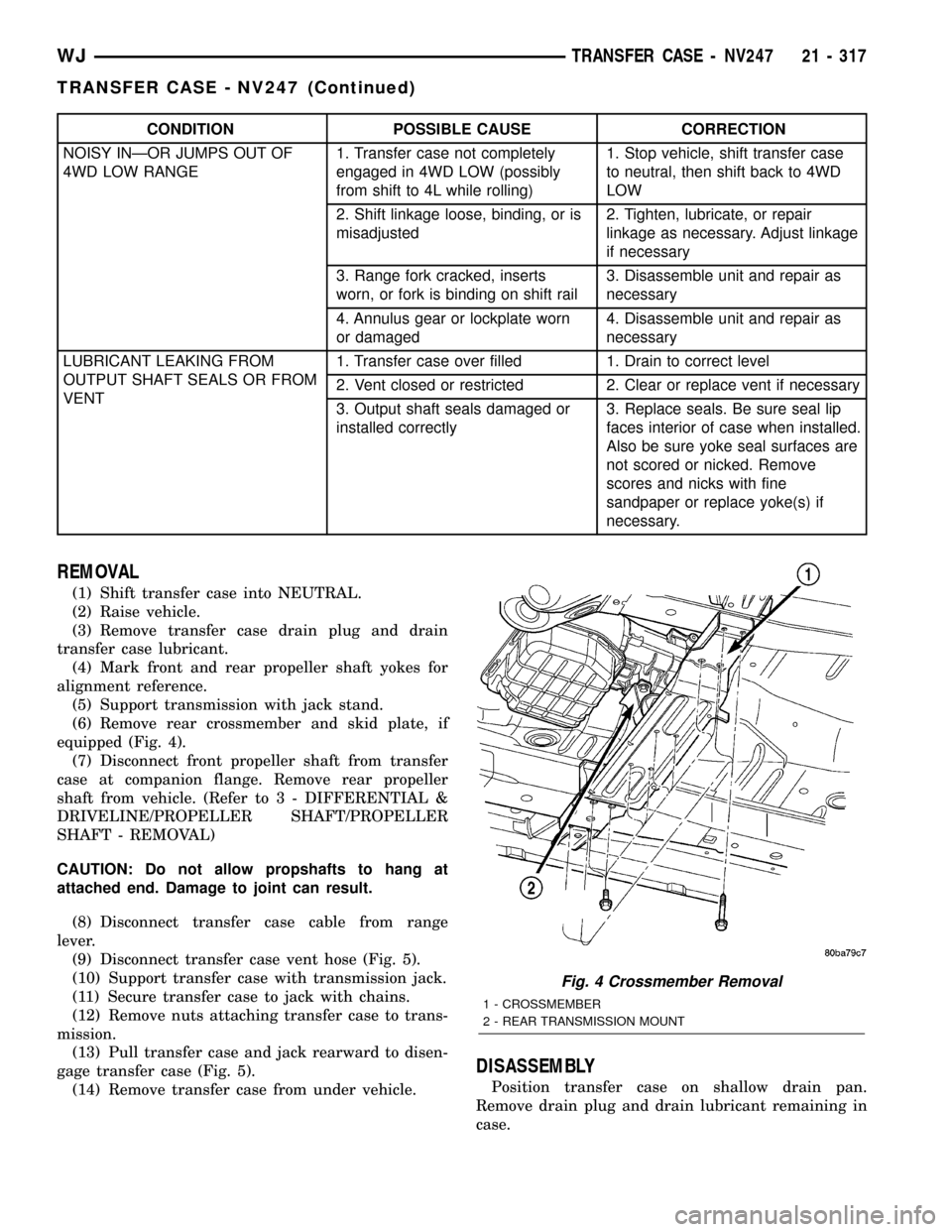
CONDITION POSSIBLE CAUSE CORRECTION
NOISY INÐOR JUMPS OUT OF
4WD LOW RANGE1. Transfer case not completely
engaged in 4WD LOW (possibly
from shift to 4L while rolling)1. Stop vehicle, shift transfer case
to neutral, then shift back to 4WD
LOW
2. Shift linkage loose, binding, or is
misadjusted2. Tighten, lubricate, or repair
linkage as necessary. Adjust linkage
if necessary
3. Range fork cracked, inserts
worn, or fork is binding on shift rail3. Disassemble unit and repair as
necessary
4. Annulus gear or lockplate worn
or damaged4. Disassemble unit and repair as
necessary
LUBRICANT LEAKING FROM
OUTPUT SHAFT SEALS OR FROM
VENT1. Transfer case over filled 1. Drain to correct level
2. Vent closed or restricted 2. Clear or replace vent if necessary
3. Output shaft seals damaged or
installed correctly3. Replace seals. Be sure seal lip
faces interior of case when installed.
Also be sure yoke seal surfaces are
not scored or nicked. Remove
scores and nicks with fine
sandpaper or replace yoke(s) if
necessary.
REMOVAL
(1) Shift transfer case into NEUTRAL.
(2) Raise vehicle.
(3) Remove transfer case drain plug and drain
transfer case lubricant.
(4) Mark front and rear propeller shaft yokes for
alignment reference.
(5) Support transmission with jack stand.
(6) Remove rear crossmember and skid plate, if
equipped (Fig. 4).
(7) Disconnect front propeller shaft from transfer
case at companion flange. Remove rear propeller
shaft from vehicle. (Refer to 3 - DIFFERENTIAL &
DRIVELINE/PROPELLER SHAFT/PROPELLER
SHAFT - REMOVAL)
CAUTION: Do not allow propshafts to hang at
attached end. Damage to joint can result.
(8) Disconnect transfer case cable from range
lever.
(9) Disconnect transfer case vent hose (Fig. 5).
(10) Support transfer case with transmission jack.
(11) Secure transfer case to jack with chains.
(12) Remove nuts attaching transfer case to trans-
mission.
(13) Pull transfer case and jack rearward to disen-
gage transfer case (Fig. 5).
(14) Remove transfer case from under vehicle.
DISASSEMBLY
Position transfer case on shallow drain pan.
Remove drain plug and drain lubricant remaining in
case.
Fig. 4 Crossmember Removal
1 - CROSSMEMBER
2 - REAR TRANSMISSION MOUNT
WJTRANSFER CASE - NV247 21 - 317
TRANSFER CASE - NV247 (Continued)