Page 1855 of 2199

(6) Connect front propeller shaft and install rear
propeller shaft. (Refer to 3 - DIFFERENTIAL &
DRIVELINE/PROPELLER SHAFT/PROPELLER
SHAFT - INSTALLATION)
(7) Fill transfer case with correct fluid. Check
transmission fluid level. Correct as necessary.
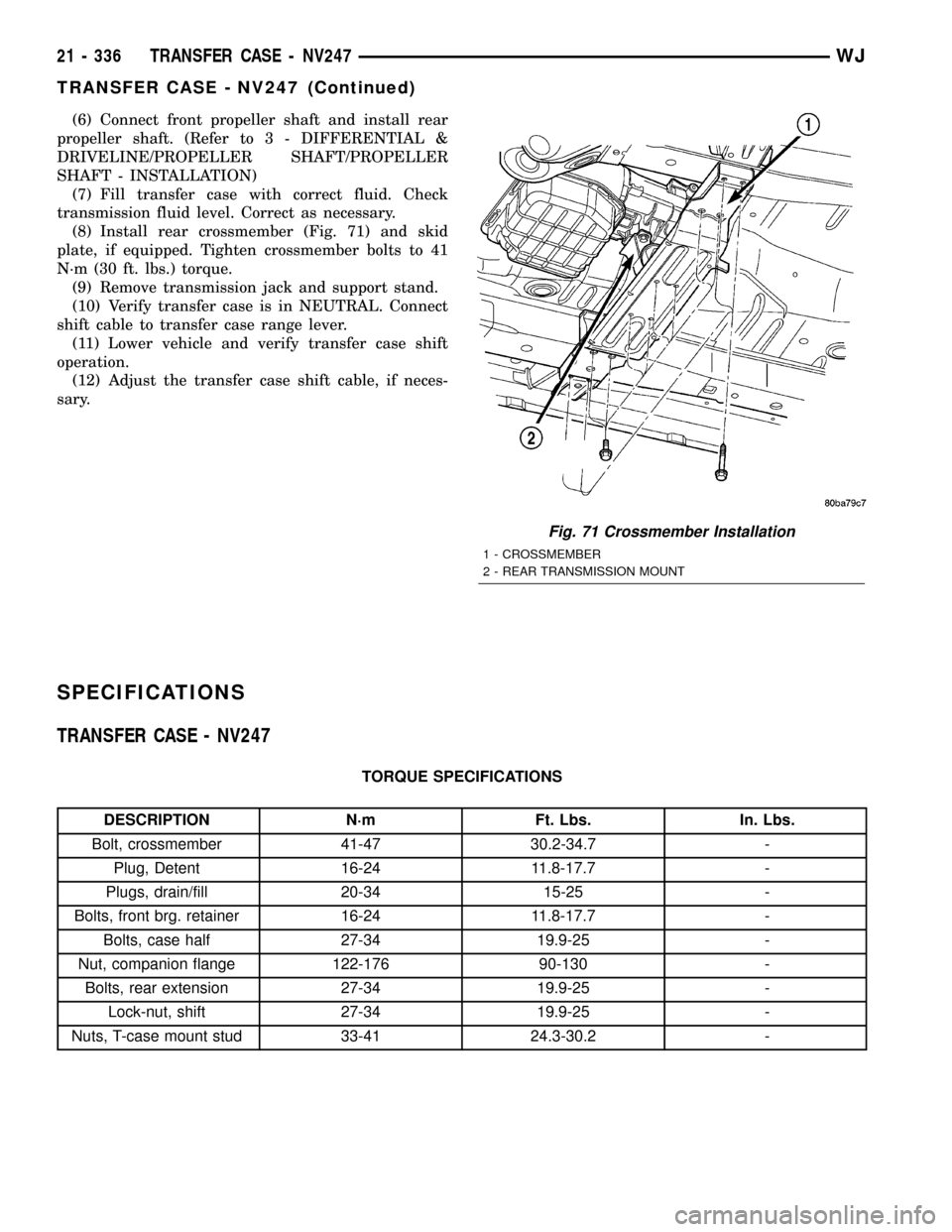
(8) Install rear crossmember (Fig. 71) and skid
plate, if equipped. Tighten crossmember bolts to 41
N´m (30 ft. lbs.) torque.
(9) Remove transmission jack and support stand.
(10) Verify transfer case is in NEUTRAL. Connect
shift cable to transfer case range lever.
(11) Lower vehicle and verify transfer case shift
operation.
(12) Adjust the transfer case shift cable, if neces-
sary.
SPECIFICATIONS
TRANSFER CASE - NV247
TORQUE SPECIFICATIONS
DESCRIPTION N´m Ft. Lbs. In. Lbs.
Bolt, crossmember 41-47 30.2-34.7 -
Plug, Detent 16-24 11.8-17.7 -
Plugs, drain/fill 20-34 15-25 -
Bolts, front brg. retainer 16-24 11.8-17.7 -
Bolts, case half 27-34 19.9-25 -
Nut, companion flange 122-176 90-130 -
Bolts, rear extension 27-34 19.9-25 -
Lock-nut, shift 27-34 19.9-25 -
Nuts, T-case mount stud 33-41 24.3-30.2 -
Fig. 71 Crossmember Installation
1 - CROSSMEMBER
2 - REAR TRANSMISSION MOUNT
21 - 336 TRANSFER CASE - NV247WJ
TRANSFER CASE - NV247 (Continued)
Page 2026 of 2199

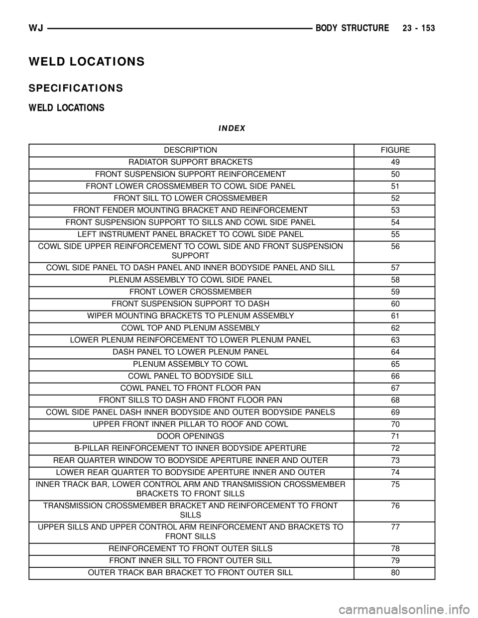
WELD LOCATIONS
SPECIFICATIONS
WELD LOCATIONS
INDEX
DESCRIPTION FIGURE
RADIATOR SUPPORT BRACKETS 49
FRONT SUSPENSION SUPPORT REINFORCEMENT 50
FRONT LOWER CROSSMEMBER TO COWL SIDE PANEL 51
FRONT SILL TO LOWER CROSSMEMBER 52
FRONT FENDER MOUNTING BRACKET AND REINFORCEMENT 53
FRONT SUSPENSION SUPPORT TO SILLS AND COWL SIDE PANEL 54
LEFT INSTRUMENT PANEL BRACKET TO COWL SIDE PANEL 55
COWL SIDE UPPER REINFORCEMENT TO COWL SIDE AND FRONT SUSPENSION
SUPPORT56
COWL SIDE PANEL TO DASH PANEL AND INNER BODYSIDE PANEL AND SILL 57
PLENUM ASSEMBLY TO COWL SIDE PANEL 58
FRONT LOWER CROSSMEMBER 59
FRONT SUSPENSION SUPPORT TO DASH 60
WIPER MOUNTING BRACKETS TO PLENUM ASSEMBLY 61
COWL TOP AND PLENUM ASSEMBLY 62
LOWER PLENUM REINFORCEMENT TO LOWER PLENUM PANEL 63
DASH PANEL TO LOWER PLENUM PANEL 64
PLENUM ASSEMBLY TO COWL 65
COWL PANEL TO BODYSIDE SILL 66
COWL PANEL TO FRONT FLOOR PAN 67
FRONT SILLS TO DASH AND FRONT FLOOR PAN 68
COWL SIDE PANEL DASH INNER BODYSIDE AND OUTER BODYSIDE PANELS 69
UPPER FRONT INNER PILLAR TO ROOF AND COWL 70
DOOR OPENINGS 71
B-PILLAR REINFORCEMENT TO INNER BODYSIDE APERTURE 72
REAR QUARTER WINDOW TO BODYSIDE APERTURE INNER AND OUTER 73
LOWER REAR QUARTER TO BODYSIDE APERTURE INNER AND OUTER 74
INNER TRACK BAR, LOWER CONTROL ARM AND TRANSMISSION CROSSMEMBER
BRACKETS TO FRONT SILLS75
TRANSMISSION CROSSMEMBER BRACKET AND REINFORCEMENT TO FRONT
SILLS76
UPPER SILLS AND UPPER CONTROL ARM REINFORCEMENT AND BRACKETS TO
FRONT SILLS77
REINFORCEMENT TO FRONT OUTER SILLS 78
FRONT INNER SILL TO FRONT OUTER SILL 79
OUTER TRACK BAR BRACKET TO FRONT OUTER SILL 80
WJBODY STRUCTURE 23 - 153
Page 2027 of 2199

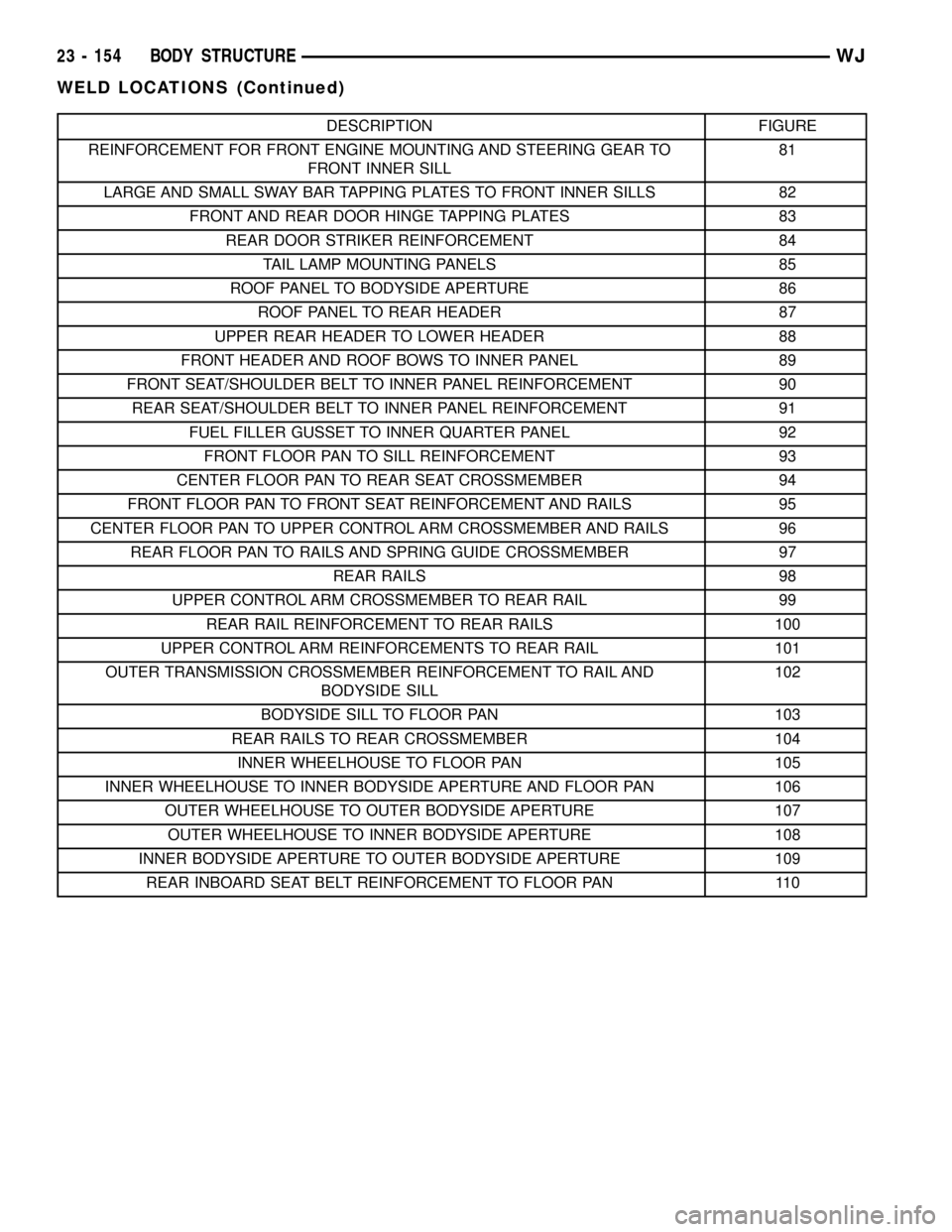
DESCRIPTION FIGURE
REINFORCEMENT FOR FRONT ENGINE MOUNTING AND STEERING GEAR TO
FRONT INNER SILL81
LARGE AND SMALL SWAY BAR TAPPING PLATES TO FRONT INNER SILLS 82
FRONT AND REAR DOOR HINGE TAPPING PLATES 83
REAR DOOR STRIKER REINFORCEMENT 84
TAIL LAMP MOUNTING PANELS 85
ROOF PANEL TO BODYSIDE APERTURE 86
ROOF PANEL TO REAR HEADER 87
UPPER REAR HEADER TO LOWER HEADER 88
FRONT HEADER AND ROOF BOWS TO INNER PANEL 89
FRONT SEAT/SHOULDER BELT TO INNER PANEL REINFORCEMENT 90
REAR SEAT/SHOULDER BELT TO INNER PANEL REINFORCEMENT 91
FUEL FILLER GUSSET TO INNER QUARTER PANEL 92
FRONT FLOOR PAN TO SILL REINFORCEMENT 93
CENTER FLOOR PAN TO REAR SEAT CROSSMEMBER 94
FRONT FLOOR PAN TO FRONT SEAT REINFORCEMENT AND RAILS 95
CENTER FLOOR PAN TO UPPER CONTROL ARM CROSSMEMBER AND RAILS 96
REAR FLOOR PAN TO RAILS AND SPRING GUIDE CROSSMEMBER 97
REAR RAILS 98
UPPER CONTROL ARM CROSSMEMBER TO REAR RAIL 99
REAR RAIL REINFORCEMENT TO REAR RAILS 100
UPPER CONTROL ARM REINFORCEMENTS TO REAR RAIL 101
OUTER TRANSMISSION CROSSMEMBER REINFORCEMENT TO RAIL AND
BODYSIDE SILL102
BODYSIDE SILL TO FLOOR PAN 103
REAR RAILS TO REAR CROSSMEMBER 104
INNER WHEELHOUSE TO FLOOR PAN 105
INNER WHEELHOUSE TO INNER BODYSIDE APERTURE AND FLOOR PAN 106
OUTER WHEELHOUSE TO OUTER BODYSIDE APERTURE 107
OUTER WHEELHOUSE TO INNER BODYSIDE APERTURE 108
INNER BODYSIDE APERTURE TO OUTER BODYSIDE APERTURE 109
REAR INBOARD SEAT BELT REINFORCEMENT TO FLOOR PAN 110
23 - 154 BODY STRUCTUREWJ
WELD LOCATIONS (Continued)
Page 2048 of 2199
Fig. 75 INNER TRACK BAR, LOWER CONTROL ARM AND TRANSMISSION CROSSMEMBER
BRACKETS TO FRONT SILLS
WJBODY STRUCTURE 23 - 175
WELD LOCATIONS (Continued)
Page 2049 of 2199
Fig. 76 TRANSMISSION CROSSMEMBER BRACKET AND REINFORCEMENT TO FRONT SILLS
23 - 176 BODY STRUCTUREWJ
WELD LOCATIONS (Continued)
Page 2072 of 2199
Fig. 102 OUTER TRANSMISSION CROSSMEMBER REINFORCEMENT TO RAIL AND BODYSIDE SILL
Fig. 103 BODYSIDE SILL TO FLOOR PAN
WJBODY STRUCTURE 23 - 199
WELD LOCATIONS (Continued)
Page 2140 of 2199

(11) Remove the bolts that secure the upper con-
denser and transmission cooler.
(12) Carefully lift the condenser out of the vehicle.
INSTALLATION
WARNING: REVIEW THE WARNINGS AND CAU-
TIONS IN THE FRONT OF THIS SECTION BEFORE
PERFORMING THE FOLLOWING OPERATION.
(Refer to 24 - HEATING & AIR CONDITIONING/
PLUMBING - WARNING) (Refer to 24 - HEATING &
AIR CONDITIONING/PLUMBING - CAUTION)
Any kinks or sharp bends in the refrigerant plumb-
ing will reduce the capacity of the entire air condi-
tioning system. Kinks and sharp bends reduce the
flow of refrigerant in the system. A good rule for the
flexible hose refrigerant lines is to keep the radius of
all bends at least ten times the diameter of the hose.
In addition, the flexible hose refrigerant lines should
be routed so they are at least 80 millimeters (3
inches) from the exhaust manifold.
High pressures are produced in the refrigerant sys-
tem when the air conditioning compressor is operat-
ing. Extreme care must be exercised to make sure
that each of the refrigerant system connections is
pressure-tight and leak free. It is a good practice to
inspect all flexible hose refrigerant lines at least once
a year to make sure they are in good condition and
properly routed.
CAUTION: Before removing the condenser, note the
location of each of the radiator and condenser air
seals. These seals are used to direct air through the
condenser and radiator. The air seals must be rein-
stalled in their proper locations in order for the air
conditioning and engine cooling systems to per-
form as designed.
(1) Carefully position the condenser in the vehicle.
(2) Install the bolts that secure the upper con-
denser and transmission cooler.
(3) Remove the tape or plugs from the refrigerant
line fittings on the condenser inlet and the discharge
line. Connect the discharge line to the condenser
inlet. Tighten the retaining nut to 28 N´m (250 in.
lbs.).
(4) Remove the tape or plugs from the refrigerant
line fittings on the condenser outlet and the liquid
line. Connect the liquid line to the condenser outlet.
Tighten the retaining nut to 28 N´m (250 in. lbs.).
(5) Install the headlamp mounting module and
front fascia. Refer to Body for the procedure.
(6) Install the engine air filter inlet duct.
(7) Install the bolts that secure the radiator to the
upper crossmember.(8) Install the nuts that secure the hood latch and
brace to the upper crossmember.
(9) Install the headlamps in their mounts.
(10) Install the screws attaching the grille and
headlamp mounting module to the upper crossmem-
ber of the vehicle. Refer to Body for this and further
steps in the procedure.
(11) Evacuate and Recharge the refrigerant sys-
tem. (Refer to 24 - HEATING & AIR CONDITION-
ING/PLUMBING - STANDARD PROCEDURE -
REFRIGERANT SYSTEM EVACUATE) (Refer to 24 -
HEATING & AIR CONDITIONING/PLUMBING -
STANDARD PROCEDURE - REFRIGERANT SYS-
TEM CHARGE)
(12) Connect the battery negative cable.
NOTE: If the condenser is replaced, add 30 millili-
ters (1 fluid ounce) of refrigerant oil to the refriger-
ant system. Use only refrigerant oil of the type
recommended for the compressor in the vehicle.
(Refer to 24 - HEATING & AIR CONDITIONING/
PLUMBING/REFRIGERANT OIL - DESCRIPTION)
A/C DISCHARGE LINE
REMOVAL
REMOVAL - 2.7L TURBO DIESEL
WARNING: REVIEW THE WARNINGS AND CAU-
TIONS IN THE FRONT OF THIS SECTION BEFORE
PERFORMING THE FOLLOWING OPERATION.
(Refer to 24 - HEATING & AIR CONDITIONING/
PLUMBING - WARNING) (Refer to 24 - HEATING &
AIR CONDITIONING/PLUMBING - CAUTION)
(1) Disconnect and isolate the negative battery
cable.
(2) Recover the refrigerant system. (Refer to 24 -
HEATING & AIR CONDITIONING/PLUMBING -
STANDARD PROCEDURE - REFRIGERANT
RECOVERY)
(3) Remove both headlamps from the vehicle. Refer
to Lamps/Lighting for the procedure.
(4) Remove the a/c high pressure transducer(Refer
to 24 - HEATING & AIR CONDITIONING/CON-
TROLS/A/C PRESSURE TRANSDUCER - REMOV-
AL).
(5) Remove the front fascia from the vehicle. Refer
to Front Fascia for the procedure (Fig. 7).
(6) Remove the refrigerant line retaining fastener
from the condenser inlet fitting. Remove the line and
cap the condenser inlet tube to prevent contamina-
tion of the system.
WJPLUMBING 24 - 63
A/C CONDENSER (Continued)
Page:
< prev 1-8 9-16 17-24