2003 JEEP GRAND CHEROKEE lamp
[x] Cancel search: lampPage 47 of 2199

DRIVELINE VIBRATION
Drive Condition Possible Cause Correction
Propeller Shaft Noise 1) Undercoating or other foreign material
on shaft.1) Clean exterior of shaft and wash with
solvent.
2) Loose U-joint clamp screws. 2) Install new clamps and screws and
tighten to proper torque.
3) Loose or bent U-joint yoke or
excessive runout.3) Install new yoke.
4) Incorrect driveline angularity. 4) Measure and correct driveline angles.
5) Rear spring center bolt not in seat. 5) Loosen spring u-bolts and seat center
bolt.
6) Worn U-joint bearings. 6) Install new U-joint.
7) Propeller shaft damaged or out of
balance.7) Installl new propeller shaft.
8) Broken rear spring. 8) Install new rear spring.
9) Excessive runout or unbalanced
condition.9) Re-index propeller shaft, test, and
evaluate.
10) Excessive drive pinion gear shaft
runout.10) Re-index propeller shaft and evaluate.
11) Excessive axle yoke deflection. 11) Inspect and replace yoke if necessary.
12) Excessive transfer case runout. 12) Inspect and repair as necessary.
Universal Joint Noise 1) Loose U-joint clamp screws. 1) Install new clamps and screws and
tighten to proper torque.
2) Lack of lubrication. 2) Replace U-joints as necessary.
BALANCE
NOTE: Removing and re-indexing the propeller
shaft 180É relative to the yoke may eliminate some
vibrations.
If propeller shaft is suspected of being unbalanced,
it can be verified with the following procedure:
(1) Raise the vehicle.
(2) Clean all the foreign material from the propel-
ler shaft and the universal joints.
(3) Inspect the propeller shaft for missing balance
weights, broken welds, and bent areas.If the pro-
peller shaft is bent, it must be replaced.
(4) Inspect the universal joints to ensure that they
are not worn, are properly installed, and are cor-
rectly aligned with the shaft.
(5) Check the universal joint clamp screws torque.
(6) Remove the wheels and tires. Install the wheel
lug nuts to retain the brake drums or rotors.
(7) Mark and number the shaft six inches from the
yoke end at four positions 90É apart.
(8) Run and accelerate the vehicle until vibration
occurs. Note the intensity and speed the vibration
occurred. Stop the engine.(9) Install a screw clamp at position 1 (Fig. 1).
Fig. 1 CLAMP SCREW - POSITION 1
1 - CLAMP
2 - SCREWDRIVER
3 - 2 PROPELLER SHAFTWJ
PROPELLER SHAFT (Continued)
Page 48 of 2199
(10) Start the engine and re-check for vibration. If
there is little or no change in vibration, move the
clamp to one of the other three positions. Repeat the
vibration test.
(11) If there is no difference in vibration at the
other positions, the source of the vibration may not
be propeller shaft.
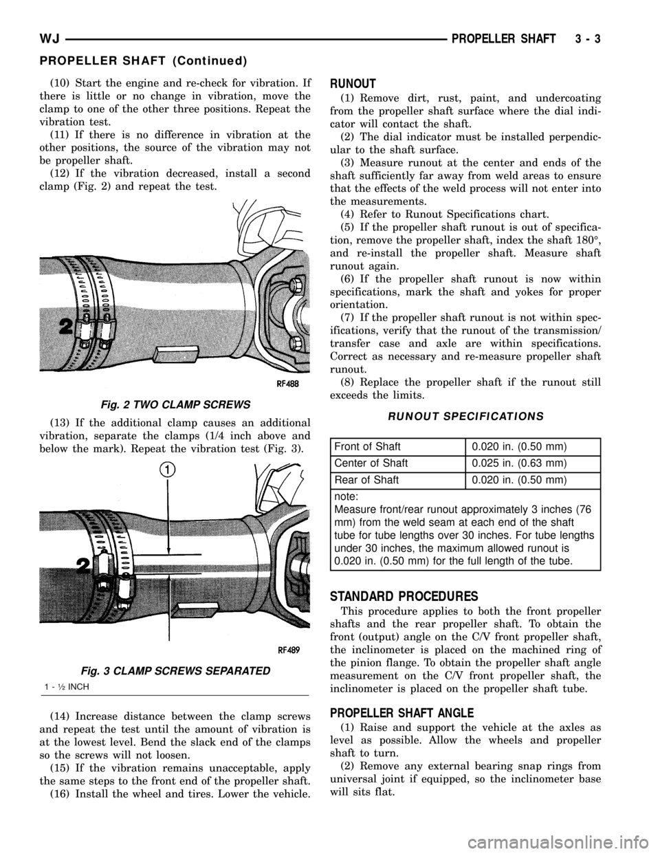
(12) If the vibration decreased, install a second
clamp (Fig. 2) and repeat the test.
(13) If the additional clamp causes an additional
vibration, separate the clamps (1/4 inch above and
below the mark). Repeat the vibration test (Fig. 3).
(14) Increase distance between the clamp screws
and repeat the test until the amount of vibration is
at the lowest level. Bend the slack end of the clamps
so the screws will not loosen.
(15) If the vibration remains unacceptable, apply
the same steps to the front end of the propeller shaft.
(16) Install the wheel and tires. Lower the vehicle.RUNOUT
(1) Remove dirt, rust, paint, and undercoating
from the propeller shaft surface where the dial indi-
cator will contact the shaft.
(2) The dial indicator must be installed perpendic-
ular to the shaft surface.
(3) Measure runout at the center and ends of the
shaft sufficiently far away from weld areas to ensure
that the effects of the weld process will not enter into
the measurements.
(4) Refer to Runout Specifications chart.
(5) If the propeller shaft runout is out of specifica-
tion, remove the propeller shaft, index the shaft 180É,
and re-install the propeller shaft. Measure shaft
runout again.
(6) If the propeller shaft runout is now within
specifications, mark the shaft and yokes for proper
orientation.
(7) If the propeller shaft runout is not within spec-
ifications, verify that the runout of the transmission/
transfer case and axle are within specifications.
Correct as necessary and re-measure propeller shaft
runout.
(8) Replace the propeller shaft if the runout still
exceeds the limits.
RUNOUT SPECIFICATIONS
Front of Shaft 0.020 in. (0.50 mm)
Center of Shaft 0.025 in. (0.63 mm)
Rear of Shaft 0.020 in. (0.50 mm)
note:
Measure front/rear runout approximately 3 inches (76
mm) from the weld seam at each end of the shaft
tube for tube lengths over 30 inches. For tube lengths
under 30 inches, the maximum allowed runout is
0.020 in. (0.50 mm) for the full length of the tube.
STANDARD PROCEDURES
This procedure applies to both the front propeller
shafts and the rear propeller shaft. To obtain the
front (output) angle on the C/V front propeller shaft,
the inclinometer is placed on the machined ring of
the pinion flange. To obtain the propeller shaft angle
measurement on the C/V front propeller shaft, the
inclinometer is placed on the propeller shaft tube.
PROPELLER SHAFT ANGLE
(1) Raise and support the vehicle at the axles as
level as possible. Allow the wheels and propeller
shaft to turn.
(2) Remove any external bearing snap rings from
universal joint if equipped, so the inclinometer base
will sits flat.
Fig. 2 TWO CLAMP SCREWS
Fig. 3 CLAMP SCREWS SEPARATED
1 - ó INCH
WJPROPELLER SHAFT 3 - 3
PROPELLER SHAFT (Continued)
Page 52 of 2199
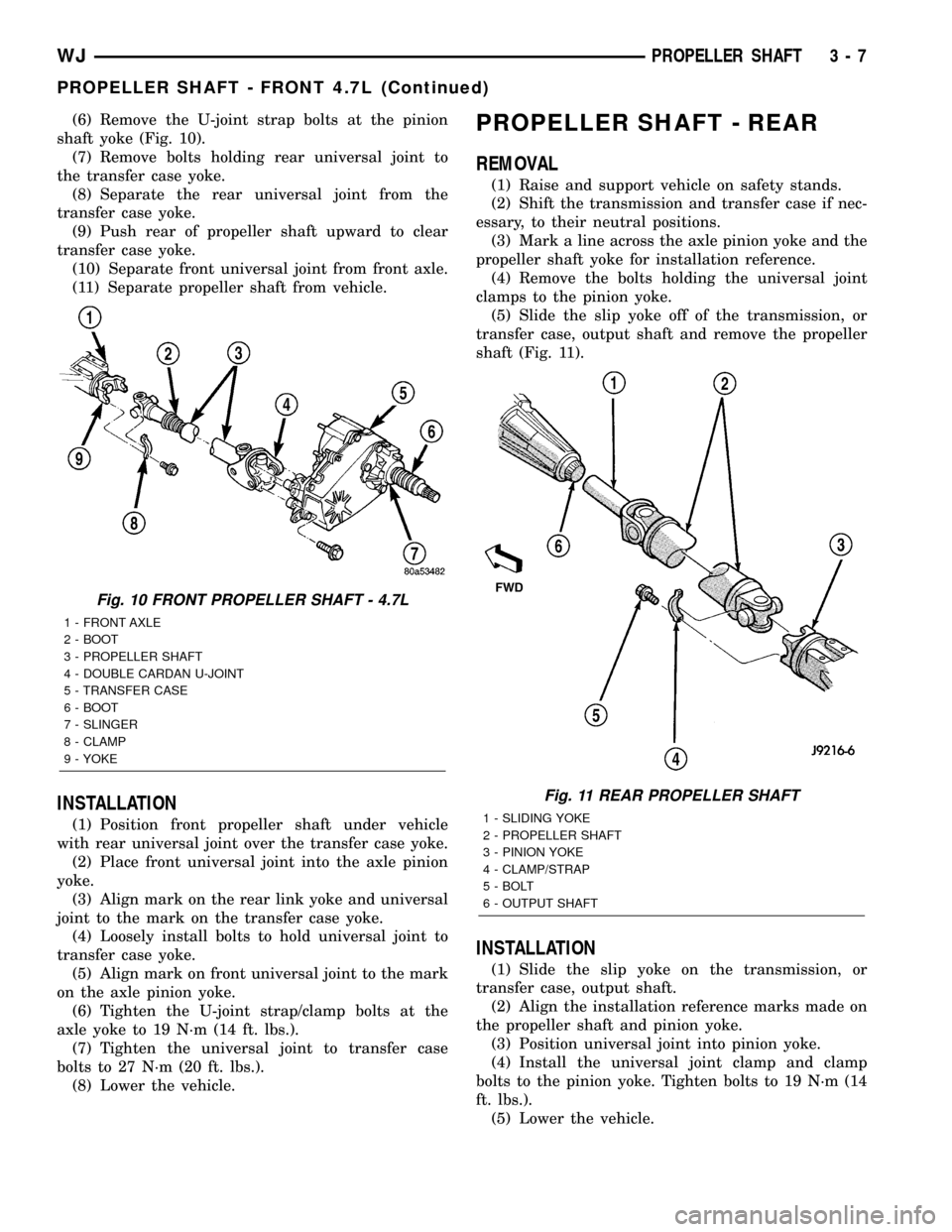
(6) Remove the U-joint strap bolts at the pinion
shaft yoke (Fig. 10).
(7) Remove bolts holding rear universal joint to
the transfer case yoke.
(8) Separate the rear universal joint from the
transfer case yoke.
(9) Push rear of propeller shaft upward to clear
transfer case yoke.
(10) Separate front universal joint from front axle.
(11) Separate propeller shaft from vehicle.
INSTALLATION
(1) Position front propeller shaft under vehicle
with rear universal joint over the transfer case yoke.
(2) Place front universal joint into the axle pinion
yoke.
(3) Align mark on the rear link yoke and universal
joint to the mark on the transfer case yoke.
(4) Loosely install bolts to hold universal joint to
transfer case yoke.
(5) Align mark on front universal joint to the mark
on the axle pinion yoke.
(6) Tighten the U-joint strap/clamp bolts at the
axle yoke to 19 N´m (14 ft. lbs.).
(7) Tighten the universal joint to transfer case
bolts to 27 N´m (20 ft. lbs.).
(8) Lower the vehicle.
PROPELLER SHAFT - REAR
REMOVAL
(1) Raise and support vehicle on safety stands.
(2) Shift the transmission and transfer case if nec-
essary, to their neutral positions.
(3) Mark a line across the axle pinion yoke and the
propeller shaft yoke for installation reference.
(4) Remove the bolts holding the universal joint
clamps to the pinion yoke.
(5) Slide the slip yoke off of the transmission, or
transfer case, output shaft and remove the propeller
shaft (Fig. 11).
INSTALLATION
(1) Slide the slip yoke on the transmission, or
transfer case, output shaft.
(2) Align the installation reference marks made on
the propeller shaft and pinion yoke.
(3) Position universal joint into pinion yoke.
(4) Install the universal joint clamp and clamp
bolts to the pinion yoke. Tighten bolts to 19 N´m (14
ft. lbs.).
(5) Lower the vehicle.
Fig. 10 FRONT PROPELLER SHAFT - 4.7L
1 - FRONT AXLE
2 - BOOT
3 - PROPELLER SHAFT
4 - DOUBLE CARDAN U-JOINT
5 - TRANSFER CASE
6 - BOOT
7 - SLINGER
8 - CLAMP
9 - YOKE
Fig. 11 REAR PROPELLER SHAFT
1 - SLIDING YOKE
2 - PROPELLER SHAFT
3 - PINION YOKE
4 - CLAMP/STRAP
5 - BOLT
6 - OUTPUT SHAFT
WJPROPELLER SHAFT 3 - 7
PROPELLER SHAFT - FRONT 4.7L (Continued)
Page 77 of 2199
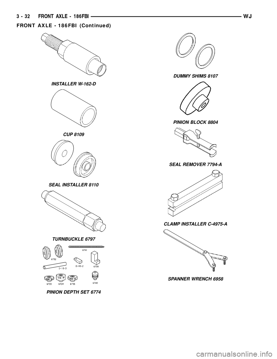
INSTALLER W-162-D
CUP 8109
SEAL INSTALLER 8110
TURNBUCKLE 6797
PINION DEPTH SET 6774
DUMMY SHIMS 8107
PINION BLOCK 8804
SEAL REMOVER 7794-A
CLAMP INSTALLER C-4975-A
SPANNER WRENCH 6958
3 - 32 FRONT AXLE - 186FBIWJ
FRONT AXLE - 186FBI (Continued)
Page 80 of 2199
AXLE SHAFT SEALS
REMOVAL
(1) Raise and support vehicle.
(2) Remove axle shafts.
(3) Remove differential assembly.
(4) Remove inner axle shaft seals with a pry bay.
INSTALLATION
(1) Remove any sealer remaining from original
seals.
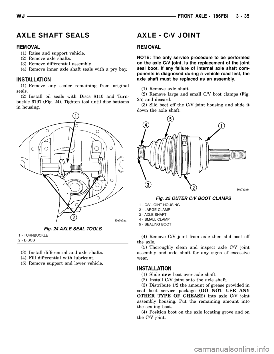
(2) Install oil seals with Discs 8110 and Turn-
buckle 6797 (Fig. 24). Tighten tool until disc bottoms
in housing.
(3) Install differential and axle shafts.
(4) Fill differential with lubricant.
(5) Remove support and lower vehicle.
AXLE - C/V JOINT
REMOVAL
NOTE: The only service procedure to be performed
on the axle C/V joint, is the replacement of the joint
seal boot. If any failure of internal axle shaft com-
ponents is diagnosed during a vehicle road test, the
axle shaft must be replaced as an assembly.
(1) Remove axle shaft.
(2) Remove large and small C/V boot clamps (Fig.
25) and discard.
(3) Slid boot off the C/V joint housing and slide it
down the axle shaft.
(4) Remove C/V joint from axle then slid boot off
the axle.
(5) Thoroughly clean and inspect axle C/V joint
assembly and axle shaft for any signs of excessive
wear.
INSTALLATION
(1) Slidenewboot over axle shaft.
(2) Install C/V joint onto the axle shaft.
(3) Distribute 1/2 the amount of grease provided in
seal boot service package(DO NOT USE ANY
OTHER TYPE OF GREASE)into axle C/V joint
assembly housing. Put the remaining amount into
the sealing boot.
(4) Position boot on the axle locating grove and on
the C/V joint.
Fig. 24 AXLE SEAL TOOLS
1 - TURNBUCKLE
2 - DISCS
Fig. 25 OUTER C/V BOOT CLAMPS
1 - C/V JOINT HOUSING
2 - LARGE CLAMP
3 - AXLE SHAFT
4 - SMALL CLAMP
5 - SEALING BOOT
WJFRONT AXLE - 186FBI 3 - 35
Page 81 of 2199
CAUTION: Boot must not be dimpled, stretched or
out of shape in any way. If not shaped correctly,
equalize pressure in boot and shape it by hand.
(5) Install the two boot clamps.
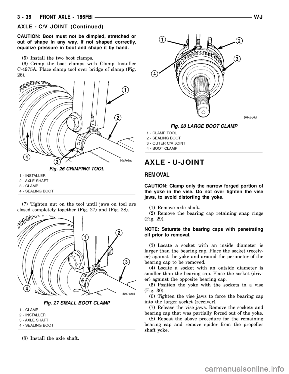
(6) Crimp the boot clamps with Clamp Installer
C-4975A. Place clamp tool over bridge of clamp (Fig.
26).
(7) Tighten nut on the tool until jaws on tool are
closed completely together (Fig. 27) and (Fig. 28).
(8) Install the axle shaft.
AXLE - U-JOINT
REMOVAL
CAUTION: Clamp only the narrow forged portion of
the yoke in the vise. Do not over tighten the vise
jaws, to avoid distorting the yoke.
(1) Remove axle shaft.
(2) Remove the bearing cap retaining snap rings
(Fig. 29).
NOTE: Saturate the bearing caps with penetrating
oil prior to removal.
(3) Locate a socket with an inside diameter is
larger than the bearing cap. Place the socket (receiv-
er) against the yoke and around the perimeter of the
bearing cap to be removed.
(4) Locate a socket with an outside diameter is
smaller than the bearing cap. Place the socket (driv-
er) against the opposite bearing cap.
(5) Position the yoke with the sockets in a vise
(Fig. 30).
(6) Tighten the vise jaws to force the bearing cap
into the larger socket (receiver).
(7) Release the vise jaws. Remove the sockets and
bearing cap that was partially forced out of the yoke.
(8) Repeat the above procedure for the remaining
bearing cap and remove spider from the propeller
shaft yoke.
Fig. 26 CRIMPING TOOL
1 - INSTALLER
2 - AXLE SHAFT
3 - CLAMP
4 - SEALING BOOT
Fig. 27 SMALL BOOT CLAMP
1 - CLAMP
2 - INSTALLER
3 - AXLE SHAFT
4 - SEALING BOOT
Fig. 28 LARGE BOOT CLAMP
1 - CLAMP TOOL
2 - SEALING BOOT
3 - OUTER C/V JOINT
4 - BOOT CLAMP
3 - 36 FRONT AXLE - 186FBIWJ
AXLE - C/V JOINT (Continued)
Page 85 of 2199

²New Bearings: 1.7 to 3.4 N´m (15 to 30 in. lbs.).
(9) Install propeller shaft with reference marks
aligned.
(10) Install brake rotors and calipers.
(11) Add gear lubricant if necessary.
(12) Install wheel and tire assemblies.
(13) Lower vehicle.
DIFFERENTIAL
REMOVAL
(1) Raise and support the vehicle.
(2) Remove lubricant fill hole plug from the differ-
ential housing cover.
(3) Remove differential cover and drain lubricant.
(4) Clean the housing cavity with a flushing oil,
light engine oil or lint free cloth.Never use water,
steam, kerosene or gasoline for cleaning.
(5) Remove hub bearings and axle shafts.
(6) Note installation reference letters stamped on
the bearing caps and housing machined sealing sur-
face (Fig. 38).
(7) Loosen the differential bearing cap bolts.
(8) Position Spreader W-129-B with Adapter Kit
6987B on differential locating holes (Fig. 39). Install
hold down clamps and tighten the tool turnbuckle
finger-tight.
Fig. 37 PINION COMPANION FLANGE
1 - COMPANION FLNAGE
2 - DIFFERENTIAL HOUSING
3 - SPANNER WRENCH
Fig. 38 BEARING CAP IDENTIFICATION
1 - REFERENCE LETTERS
2 - REFERENCE LETTERS
Fig. 39 DIFFERENTIAL SPREADER LOCATION
1 - DIFFERENTIAL HOUSING
2 - ADAPTER
3 - HOLD DOWN CLAMPS
4 - SPREADER
5 - TURNBUCKLE
3 - 40 FRONT AXLE - 186FBIWJ
COLLAPSIBLE SPACER (Continued)
Page 86 of 2199
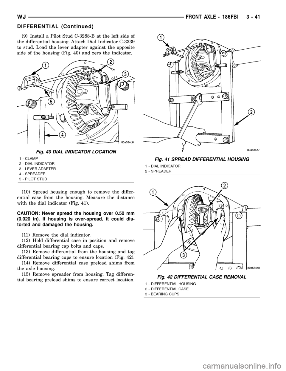
(9) Install a Pilot Stud C-3288-B at the left side of
the differential housing. Attach Dial Indicator C-3339
to stud. Load the lever adapter against the opposite
side of the housing (Fig. 40) and zero the indicator.
(10) Spread housing enough to remove the differ-
ential case from the housing. Measure the distance
with the dial indicator (Fig. 41).
CAUTION: Never spread the housing over 0.50 mm
(0.020 in). If housing is over-spread, it could dis-
torted and damaged the housing.
(11) Remove the dial indicator.
(12) Hold differential case in position and remove
differential bearing cap bolts and caps.
(13) Remove differential from the housing and tag
differential bearing cups to ensure location (Fig. 42).
(14) Remove differential case preload shims from
the axle housing.
(15) Remove spreader from housing. Tag differen-
tial bearing preload shims to ensure correct location.
Fig. 40 DIAL INDICATOR LOCATION
1 - CLAMP
2 - DIAL INDICATOR
3 - LEVER ADAPTER
4 - SPREADER
5 - PILOT STUDFig. 41 SPREAD DIFFERENTIAL HOUSING
1 - DIAL INDICATOR
2 - SPREADER
Fig. 42 DIFFERENTIAL CASE REMOVAL
1 - DIFFERENTIAL HOUSING
2 - DIFFERENTIAL CASE
3 - BEARING CUPS
WJFRONT AXLE - 186FBI 3 - 41
DIFFERENTIAL (Continued)