2003 JEEP GRAND CHEROKEE camshaft torque
[x] Cancel search: camshaft torquePage 1273 of 2199
ENGINE BLOCK
CLEANING
Thoroughly clean the oil pan and engine block gas-
ket surfaces.
Use compressed air to clean out:
²The galley at the oil filter adaptor hole.
²The front and rear oil galley holes.
²The feed holes for the crankshaft main bearings.
Once the block has been completely cleaned, apply
Loctite PST pipe sealant with Teflon 592 to the
threads of the front and rear oil galley plugs. Tighten
the plugs to 34 N´m (25 ft. lbs.) torque.
INSPECTION
(1) It is mandatory to use a dial bore gauge to
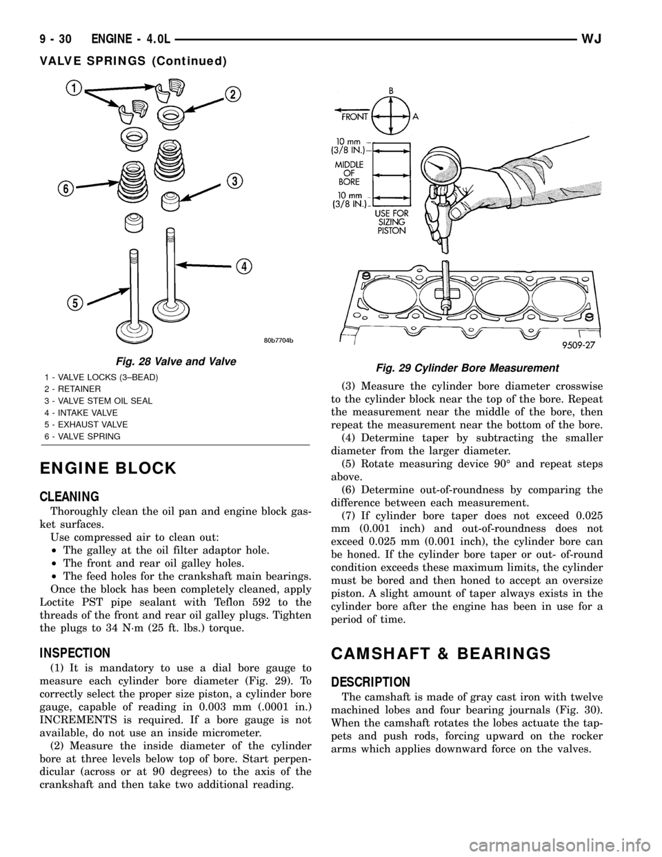
measure each cylinder bore diameter (Fig. 29). To
correctly select the proper size piston, a cylinder bore
gauge, capable of reading in 0.003 mm (.0001 in.)
INCREMENTS is required. If a bore gauge is not
available, do not use an inside micrometer.
(2) Measure the inside diameter of the cylinder
bore at three levels below top of bore. Start perpen-
dicular (across or at 90 degrees) to the axis of the
crankshaft and then take two additional reading.(3) Measure the cylinder bore diameter crosswise
to the cylinder block near the top of the bore. Repeat
the measurement near the middle of the bore, then
repeat the measurement near the bottom of the bore.
(4) Determine taper by subtracting the smaller
diameter from the larger diameter.
(5) Rotate measuring device 90É and repeat steps
above.
(6) Determine out-of-roundness by comparing the
difference between each measurement.
(7) If cylinder bore taper does not exceed 0.025
mm (0.001 inch) and out-of-roundness does not
exceed 0.025 mm (0.001 inch), the cylinder bore can
be honed. If the cylinder bore taper or out- of-round
condition exceeds these maximum limits, the cylinder
must be bored and then honed to accept an oversize
piston. A slight amount of taper always exists in the
cylinder bore after the engine has been in use for a
period of time.
CAMSHAFT & BEARINGS
DESCRIPTION
The camshaft is made of gray cast iron with twelve
machined lobes and four bearing journals (Fig. 30).
When the camshaft rotates the lobes actuate the tap-
pets and push rods, forcing upward on the rocker
arms which applies downward force on the valves.
Fig. 28 Valve and Valve
1 - VALVE LOCKS (3±BEAD)
2 - RETAINER
3 - VALVE STEM OIL SEAL
4 - INTAKE VALVE
5 - EXHAUST VALVE
6 - VALVE SPRINGFig. 29 Cylinder Bore Measurement
9 - 30 ENGINE - 4.0LWJ
VALVE SPRINGS (Continued)
Page 1277 of 2199
BEARING-TO-JOURNAL CLEARANCE
(1) Wipe the oil from the connecting rod journal.
(2) Use short rubber hose sections over rod bolts
during installation.
(3) Lubricate the upper bearing insert and install
in connecting rod.
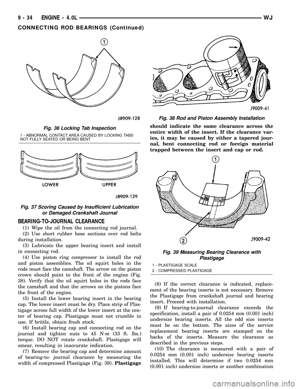
(4) Use piston ring compressor to install the rod
and piston assemblies. The oil squirt holes in the
rods must face the camshaft. The arrow on the piston
crown should point to the front of the engine (Fig.
38). Verify that the oil squirt holes in the rods face
the camshaft and that the arrows on the pistons face
the front of the engine.
(5) Install the lower bearing insert in the bearing
cap. The lower insert must be dry. Place strip of Plas-
tigage across full width of the lower insert at the cen-
ter of bearing cap. Plastigage must not crumble in
use. If brittle, obtain fresh stock.
(6) Install bearing cap and connecting rod on the
journal and tighten nuts to 45 N´m (33 ft. lbs.)
torque. DO NOT rotate crankshaft. Plastigage will
smear, resulting in inaccurate indication.
(7) Remove the bearing cap and determine amount
of bearing-to- journal clearance by measuring the
width of compressed Plastigage (Fig. 39).Plastigageshould indicate the same clearance across the
entire width of the insert. If the clearance var-
ies, it may be caused by either a tapered jour-
nal, bent connecting rod or foreign material
trapped between the insert and cap or rod.
(8) If the correct clearance is indicated, replace-
ment of the bearing inserts is not necessary. Remove
the Plastigage from crankshaft journal and bearing
insert. Proceed with installation.
(9) If bearing-to-journal clearance exceeds the
specification, install a pair of 0.0254 mm (0.001 inch)
undersize bearing inserts. All the odd size inserts
must be on the bottom. The sizes of the service
replacement bearing inserts are stamped on the
backs of the inserts. Measure the clearance as
described in the previous steps.
(10) The clearance is measured with a pair of
0.0254 mm (0.001 inch) undersize bearing inserts
installed. This will determine if two 0.0254 mm
(0.001 inch) undersize inserts or another combination
Fig. 36 Locking Tab Inspection
1 - ABNORMAL CONTACT AREA CAUSED BY LOCKING TABS
NOT FULLY SEATED OR BEING BENT
Fig. 37 Scoring Caused by Insufficient Lubrication
or Damaged Crankshaft Journal
Fig. 38 Rod and Piston Assembly Installation
Fig. 39 Measuring Bearing Clearance with
Plastigage
1 - PLASTIGAGE SCALE
2 - COMPRESSED PLASTIGAGE
9 - 34 ENGINE - 4.0LWJ
CONNECTING ROD BEARINGS (Continued)
Page 1294 of 2199
crankshaft is drilled internally to pass oil from the
main bearing journals (except number 4 main bear-
ing journal) to the connecting rod journals. Each con-
necting rod bearing cap has a small squirt hole, oil
passes through the squirt hole and is thrown off as
the rod rotates. This oil throwoff lubricates the cam-
shaft lobes, distributor drive gear, cylinder walls, and
piston pins.
The hydraulic valve tappets receive oil directly
from the main oil gallery. Oil is provided to the cam-
shaft bearing through galleries. The front camshaft
bearing journal passes oil through the camshaft
sprocket to the timing chain. Oil drains back to the
oil pan under the number one main bearing cap.
The oil supply for the rocker arms and bridged
pivot assemblies is provided by the hydraulic valve
tappets which pass oil through hollow push rods to a
hole in the corresponding rocker arm. Oil from the
rocker arm lubricates the valve train components,
then passes down through the push rod guide holes
in the cylinder head past the valve tappet area, and
returns to the oil pan (Fig. 73).
DIAGNOSIS AND TESTING
DIAGNOSIS AND TESTING - ENGINE OIL
PRESSURE
(1) Disconnect connector and remove oil pressure
sending unit.
(2) Install Oil Pressure Line and Gauge Tool
C-3292 or equivalent. Start engine and record pres-
sure. (Refer to 9 - ENGINE - SPECIFICATIONS) for
the correct pressures.
DIAGNOSIS AND TESTING - ENGINE OIL LEAK
Begin with a thorough visual inspection of the
engine, particularly at the area of the suspected leak.
If an oil leak source is not readily identifiable, the
following steps should be followed:
(1) Do not clean or degrease the engine at this
time because some solvents may cause rubber to
swell, temporarily stopping the leak.
(2) Add an oil soluble dye (use as recommended by
manufacturer). Start the engine and let idle for
approximately 15 minutes. Check the oil dipstick to
make sure the dye is thoroughly mixed as indicated
with a bright yellow color under a black light.
(3) Using a black light, inspect the entire engine
for fluorescent dye, particularly at the suspected area
of oil leak. If the oil leak is found and identified,
repair per service manual instructions.
(4) If dye is not observed, drive the vehicle at var-
ious speeds for approximately 24km (15 miles), and
repeat inspection.If the oil leak source is not pos-itively identified at this time, proceed with the air
leak detection test method.
Air Leak Detection Test Method
(1) Disconnect the breather cap to air cleaner hose
at the breather cap end. Cap or plug breather cap
nipple.
(2) Remove the CCV valve from the cylinder head
cover. Cap or plug the CCV valve grommet.
(3) Attach an air hose with pressure gauge and
regulator to the dipstick tube.
CAUTION: Do not subject the engine assembly to
more than 20.6 kpa (3 PSI) of test pressure.
(4) Gradually apply air pressure from 1 psi to 2.5
psi maximum while applying soapy water at the sus-
pected source. Adjust the regulator to the suitable
test pressure that provide the best bubbles which
will pinpoint the leak source. If the oil leak is
detected and identified, repair per service informa-
tion procedures.
(5) If the leakage occurs at the rear oil seal area,
INSPECTION FOR REAR SEAL AREA LEAKS .
(6) If no leaks are detected, turn off the air supply
and remove the air hose and all plugs and caps.
Install the CCV valve and breather cap hose.
(7) Clean the oil off the suspect oil leak area using
a suitable solvent. Drive the vehicle at various
speeds approximately 24 km (15 miles). Inspect the
engine for signs of an oil leak by using a black light.
INSPECTION FOR REAR SEAL AREA LEAKS
Since it is sometimes difficult to determine the
source of an oil leak in the rear seal area of the
engine, a more involved inspection is necessary. The
following steps should be followed to help pinpoint
the source of the leak.
If the leakage occurs at the crankshaft rear oil seal
area:
(1) Disconnect the battery.
(2) Raise the vehicle.
(3) Remove torque converter or clutch housing
cover and inspect rear of block for evidence of oil.
Use a black light to check for the oil leak:
(a) Circular spray pattern generally indicates
seal leakage or crankshaft damage.
(b) Where leakage tends to run straight down,
possible causes are a porous block, distributor seal,
camshaft bore cup plugs oil galley pipe plugs, oil
filter runoff, and main bearing cap to cylinder
block mating surfaces.
(4) If no leaks are detected, pressurize the crank-
case as outlined in the, Inspection (Engine oil Leaks
in general)
CAUTION: Do not exceed 20.6 kPa (3 psi).
WJENGINE - 4.0L 9 - 51
LUBRICATION (Continued)
Page 1303 of 2199
TIMING BELT/CHAIN AND
SPROCKETS
REMOVAL
(1) Disconnect negative cable from battery.
(2) Remove the fan and shroud (Refer to 7 -
COOLING/ENGINE/RADIATOR FAN - REMOVAL).
(3) Remove the serpentine drive belt (Refer to 7 -
COOLING/ACCESSORY DRIVE/DRIVE BELTS -
REMOVAL).
(4) Remove the crankshaft vibration damper (Refer
to 9 - ENGINE/ENGINE BLOCK/VIBRATION
DAMPER - REMOVAL).
(5) Remove the timing case cover (Refer to 9 -
ENGINE/VALVE TIMING/TIMING BELT / CHAIN
COVER(S) - REMOVAL).
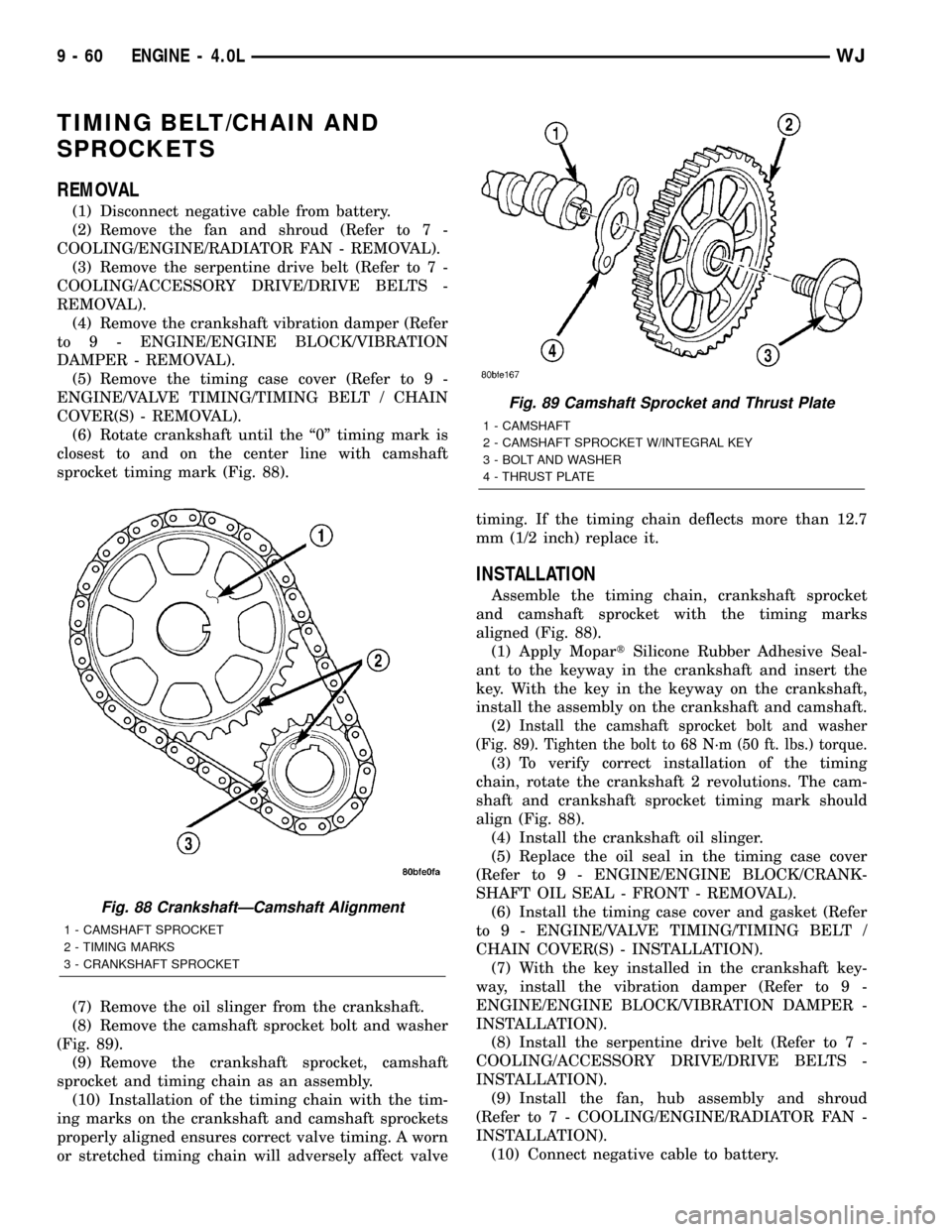
(6) Rotate crankshaft until the ª0º timing mark is
closest to and on the center line with camshaft
sprocket timing mark (Fig. 88).
(7) Remove the oil slinger from the crankshaft.
(8) Remove the camshaft sprocket bolt and washer
(Fig. 89).
(9) Remove the crankshaft sprocket, camshaft
sprocket and timing chain as an assembly.
(10) Installation of the timing chain with the tim-
ing marks on the crankshaft and camshaft sprockets
properly aligned ensures correct valve timing. A worn
or stretched timing chain will adversely affect valvetiming. If the timing chain deflects more than 12.7
mm (1/2 inch) replace it.
INSTALLATION
Assemble the timing chain, crankshaft sprocket
and camshaft sprocket with the timing marks
aligned (Fig. 88).
(1) Apply MopartSilicone Rubber Adhesive Seal-
ant to the keyway in the crankshaft and insert the
key. With the key in the keyway on the crankshaft,
install the assembly on the crankshaft and camshaft.
(2)
Install the camshaft sprocket bolt and washer
(Fig. 89). Tighten the bolt to 68 N´m (50 ft. lbs.) torque.
(3) To verify correct installation of the timing
chain, rotate the crankshaft 2 revolutions. The cam-
shaft and crankshaft sprocket timing mark should
align (Fig. 88).
(4) Install the crankshaft oil slinger.
(5) Replace the oil seal in the timing case cover
(Refer to 9 - ENGINE/ENGINE BLOCK/CRANK-
SHAFT OIL SEAL - FRONT - REMOVAL).
(6) Install the timing case cover and gasket (Refer
to 9 - ENGINE/VALVE TIMING/TIMING BELT /
CHAIN COVER(S) - INSTALLATION).
(7) With the key installed in the crankshaft key-
way, install the vibration damper (Refer to 9 -
ENGINE/ENGINE BLOCK/VIBRATION DAMPER -
INSTALLATION).
(8) Install the serpentine drive belt (Refer to 7 -
COOLING/ACCESSORY DRIVE/DRIVE BELTS -
INSTALLATION).
(9) Install the fan, hub assembly and shroud
(Refer to 7 - COOLING/ENGINE/RADIATOR FAN -
INSTALLATION).
(10) Connect negative cable to battery.
Fig. 88 CrankshaftÐCamshaft Alignment
1 - CAMSHAFT SPROCKET
2 - TIMING MARKS
3 - CRANKSHAFT SPROCKET
Fig. 89 Camshaft Sprocket and Thrust Plate
1 - CAMSHAFT
2 - CAMSHAFT SPROCKET W/INTEGRAL KEY
3 - BOLT AND WASHER
4 - THRUST PLATE
9 - 60 ENGINE - 4.0LWJ
Page 1304 of 2199
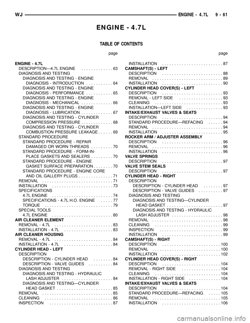
ENGINE - 4.7L
TABLE OF CONTENTS
page page
ENGINE - 4.7L
DESCRIPTIONÐ4.7L ENGINE.............63
DIAGNOSIS AND TESTING
DIAGNOSIS AND TESTING - ENGINE
DIAGNOSIS - INTRODUCTION...........64
DIAGNOSIS AND TESTING - ENGINE
DIAGNOSIS - PERFORMANCE...........65
DIAGNOSIS AND TESTING - ENGINE
DIAGNOSIS - MECHANICAL.............66
DIAGNOSIS AND TESTING - ENGINE
DIAGNOSIS - LUBRICATION.............67
DIAGNOSIS AND TESTING - CYLINDER
COMPRESSION PRESSURE.............68
DIAGNOSIS AND TESTING - CYLINDER
COMBUSTION PRESSURE LEAKAGE......69
STANDARD PROCEDURE
STANDARD PROCEDURE - REPAIR
DAMAGED OR WORN THREADS.........70
STANDARD PROCEDURE - FORM-IN-
PLACE GASKETS AND SEALERS.........70
STANDARD PROCEDURE - ENGINE
GASKET SURFACE PREPARATION........70
STANDARD PROCEDURE - ENGINE CORE
AND OIL GALLERY PLUGS..............71
REMOVAL.............................71
INSTALLATION.........................73
SPECIFICATIONS
4.7L ENGINE.........................74
SPECIFICATIONS - 4.7L H.O. ENGINE.....77
TORQUE............................79
SPECIAL TOOLS
4.7L ENGINE.........................80
AIR CLEANER ELEMENT
REMOVAL - 4.7L........................83
INSTALLATION - 4.7L....................83
AIR CLEANER HOUSING
REMOVAL - 4.7L........................84
INSTALLATION - 4.7L....................84
CYLINDER HEAD - LEFT
DESCRIPTION
DESCRIPTION - CYLINDER HEAD........84
DESCRIPTION - VALVE GUIDES..........84
DIAGNOSIS AND TESTING
DIAGNOSIS AND TESTING - HYDRAULIC
LASH ADJUSTER.....................84
DIAGNOSIS AND TESTINGÐCYLINDER
HEAD GASKET.......................85
REMOVAL.............................85
CLEANING............................86
INSPECTION..........................87INSTALLATION.........................87
CAMSHAFT(S) - LEFT
DESCRIPTION.........................88
REMOVAL.............................89
INSTALLATION.........................90
CYLINDER HEAD COVER(S) - LEFT
DESCRIPTION.........................93
REMOVAL - LEFT SIDE..................93
CLEANING............................93
INSTALLATIONÐLEFT SIDE...............93
INTAKE/EXHAUST VALVES & SEATS
DESCRIPTION.........................94
STANDARD PROCEDUREÐREFACING......94
REMOVAL.............................94
INSTALLATION.........................95
ROCKER ARM / ADJUSTER ASSEMBLY
DESCRIPTION.........................96
REMOVAL.............................96
INSTALLATION.........................96
VALVE SPRINGS
DESCRIPTION.........................97
VALVE STEM SEALS
DESCRIPTION.........................97
CYLINDER HEAD - RIGHT
DESCRIPTION
DESCRIPTION - CYLINDER HEAD........97
DESCRIPTION - VALVE GUIDES..........97
DIAGNOSIS AND TESTING
DIAGNOSIS AND TESTINGÐCYLINDER
HEAD GASKET.......................97
DIAGNOSIS AND TESTING - HYDRAULIC
LASH ADJUSTER.....................98
REMOVAL.............................98
CLEANING............................99
INSPECTION..........................99
INSTALLATION.........................99
CAMSHAFT(S) - RIGHT
DESCRIPTION........................100
REMOVAL............................100
INSTALLATION........................102
CYLINDER HEAD COVER(S) - RIGHT
DESCRIPTION........................104
REMOVAL - RIGHT SIDE................104
CLEANING...........................104
INSTALLATION - RIGHT SIDE.............104
INTAKE/EXHAUST VALVES & SEATS
DESCRIPTION........................104
STANDARD PROCEDUREÐREFACING.....105
REMOVAL............................105
INSTALLATION........................106
WJENGINE - 4.7L 9 - 61
Page 1317 of 2199
²Camshaft Position (CMP) Sensor
²Coil Over Plugs
(10) Install generator (Refer to 8 - ELECTRICAL/
CHARGING/GENERATOR - INSTALLATION).
(11) Install radiator (Refer to 7 - COOLING/EN-
GINE/RADIATOR - INSTALLATION).
(12) Install A/C condenser (Refer to 24 - HEATING
& AIR CONDITIONING/PLUMBING/A/C CON-
DENSER - INSTALLATION).
(13) Connect radiator lower hose at the thermostat
housing.
(14) Connect the transmission oil cooler lines to
the radiator.
(15) Install A/C compressor. (Refer to 24 - HEAT-
ING & AIR CONDITIONING/PLUMBING/A/C COM-
PRESSOR - INSTALLATION).
(16) Install accessory drive belt (Refer to 7 -
COOLING/ACCESSORY DRIVE/DRIVE BELTS -
INSTALLATION) and radiator fan (Refer to 7 -
COOLING/ENGINE/RADIATOR FAN - INSTALLA-
TION).
(17) Install breathers, then connect tube to both
crankcase breathers (Fig. 5).
(18) Connect throttle and speed control cables.
(19) Install throttle body resonator assembly and
inlet hose.
(20) Raise vehicle.
(21) Connect two ground straps on the lower left
hand side of the engine and one ground strap on the
lower right side.
(22) Install torque converter bolts.
(23) Connect crankshaft position sensor (Fig. 4).
(24) Install starter.
(25) Install rubber splash shield.
CAUTION: The structural cover requires a specific
torque sequence. Failure to follow this sequence
may cause severe damage to the cover.
(26) Install structural cover (Refer to 9 - ENGINE/
ENGINE BLOCK/STRUCTURAL COVER - INSTAL-
LATION).
(27) Install exhaust crossover pipe.
(28) Install engine block heater power cable, If
equipped.
(29) Lower vehicle.
(30) Check and fill engine oil (Refer to LUBRICA-
TION & MAINTENANCE/FLUID TYPES - SPECIFI-
CATIONS).
(31) Recharge the A/C system (Refer to 24 - HEAT-
ING & AIR CONDITIONING/PLUMBING - STAN-
DARD PROCEDURE).
(32) Refill the engine cooling system (Refer to 7 -
COOLING - STANDARD PROCEDURE).
(33) Connect the battery negative cable.
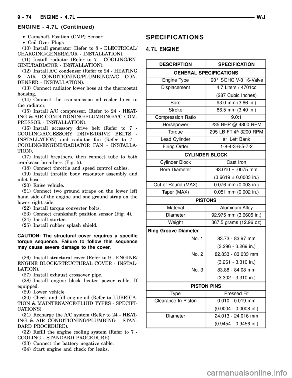
(34) Start engine and check for leaks.SPECIFICATIONS
4.7L ENGINE
DESCRIPTION SPECIFICATION
GENERAL SPECIFICATIONS
Engine Type 90É SOHC V-8 16-Valve
Displacement 4.7 Liters / 4701cc
(287 Cubic Inches)
Bore 93.0 mm (3.66 in.)
Stroke 86.5 mm (3.40 in.)
Compression Ratio 9.0:1
Horsepower 235 BHP @ 4800 RPM
Torque 295 LB-FT @ 3200 RPM
Lead Cylinder #1 Left Bank
Firing Order 1-8-4-3-6-5-7-2
CYLINDER BLOCK
Cylinder Block Cast Iron
Bore Diameter 93.010 .0075 mm
(3.6619 0.0003 in.)
Out of Round (MAX) 0.076 mm (0.003 in.)
Taper (MAX) 0.051 mm (0.002 in.)
PISTONS
Material Aluminum Alloy
Diameter 92.975 mm (3.6605 in.)
Weight 367.5 grams (12.96 oz)
Ring Groove Diameter
No. 1 83.73 - 83.97 mm
(3.296 - 3.269 in.)
No. 2 82.833 - 83.033 mm
(3.261 - 3.310 in.)
No. 3 83.88 - 84.08 mm
(3.302 - 3.310 in.)
PISTON PINS
Type Pressed Fit
Clearance In Piston 0.010 - 0.019 mm
(0.0004 - 0.0008 in.)
Diameter 24.013 - 24.016 mm
(0.9454 - 0.9456 in.)
9 - 74 ENGINE - 4.7LWJ
ENGINE - 4.7L (Continued)
Page 1322 of 2199
DESCRIPTION SPECIFICATION
Valve Lift (Zero Lash)
Intake 12.00 mm (0.4724 in.)
Exhaust 10.90 mm (0.4292 in.)
VALVE SPRING
Free Length (Approx)
Intake and Exhaust 48.92 mm (1.9259 in.)
Spring Force (Valve
Closed)
Intake and Exhaust 380.0 +/- 19.0 N @ 40.12
mm
(85.4274 lbs. @ 1.5795
in.)
Spring Force (Valve
Open)
Intake and Exhaust 1030.0 +/- 46.0 N @
28.12 mm
231.5532 lbs. @ 1.107
in.)
Number of Coils
Intake and Exhaust 7.30
Wire Diameter
Intake and Exhaust 4.77 +/- 0.03 mm x
3.80+/- .03mm
Installed Height (Spring
Seat to Bottom of
Retainer)
Nominal
Intake 40.97 mm (1.613 in.)
Exhaust 40.81 mm (1.606 in.)
CYLINDER HEAD
Gasket Thickness
(Compressed) .7 mm (0.0276 in.)
Valve Seat Angle 44.5É - 45.0É
Valve Seat Runout (MAX) 0.051 mm (0.002 in.)
Valve Seat Width
Intake 1.75 - 2.36 mm
(0.0698 - 0.0928 in.)
Exhaust 1.71 - 2.32 mm
(0.0673 - 0.0911 in.)
Guide Bore Diameter
(Std.)6.975 - 7.00 mm
(0.2747 - 0.2756 in.)DESCRIPTION SPECIFICATION
Cylinder Head Warpage
(Flatness) 0.0508 mm (0.002 in.)
OIL PUMP
Clearance Over Rotors /
End Face (MAX).035 - .095 mm
(0.0014 - 0.0038 in.)
Cover Out - of -Flat
(MAX).025 mm (0.001 in.)
Inner and Outer Rotor
Thickness 12.02 mm (0.4731 in.)
Outer Rotor Clearance
(MAX).235 mm (.0093 in.)
Outer Rotor Diameter
(MIN)85.925 mm (0.400 in.)
Tip Clearance Between
Rotors
(MAX) .150 mm (0.006 in.)
OIL PRESSURE
At Curb Idle Speed
(MIN)*25 kPa (4 psi)
@ 3000 rpm 170 - 758 kPa (25 - 110
psi)
* CAUTION: If pressure is zero at curb idle, DO
NOT run
engine at 3000 rpm.
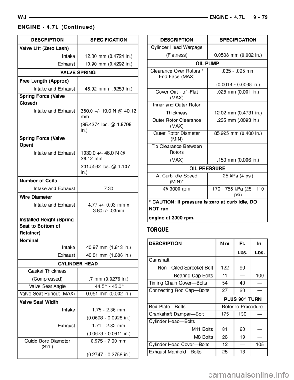
TORQUE
DESCRIPTION N´m Ft. In.
Lbs. Lbs.
Camshaft
Non - Oiled Sprocket Bolt 122 90 Ð
Bearing Cap Bolts 11 Ð 100
Timing Chain CoverÐBolts 54 40 Ð
Connecting Rod CapÐBolts 27 20 Ð
PLUS 90É TURN
Bed PlateÐBolts Refer to Procedure
Crankshaft DamperÐBolt 175 130 Ð
Cylinder HeadÐBolts
M11 Bolts 81 60 Ð
M8 Bolts 26 19 Ð
Cylinder Head CoverÐBolts 12 Ð 105
Exhaust ManifoldÐBolts 25 18 Ð
WJENGINE - 4.7L 9 - 79
ENGINE - 4.7L (Continued)
Page 1330 of 2199
INSPECTION
(1) Inspect the cylinder head for out-of-flatness,
using a straightedge and a feeler gauge. If tolerances
exceed 0.0508 mm (0.002 in.) replace the cylinder
head.
(2) Inspect the valve seats for damage. Service the
valve seats as necessary.(3) Inspect the valve guides for wear, cracks or
looseness. If either condition exist, replace the cylin-
der head.
INSTALLATION
NOTE: The cylinder head bolts are tightened using
a torque plus angle procedure. The bolts must be
examined BEFORE reuse. If the threads are necked
down the bolts should be replaced.
Necking can be checked by holding a straight edge
against the threads. If all the threads do not contact
the scale, the bolt should be replaced (Fig. 13).
CAUTION: When cleaning cylinder head and cylin-
der block surfaces, DO NOT use a metal scraper
because the surfaces could be cut or ground. Use
only a wooden or plastic scraper.
(1) Clean the cylinder head and cylinder block
mating surfaces (Refer to 9 - ENGINE - STANDARD
PROCEDURE).
(2) Position the new cylinder head gasket on the
locating dowels.
CAUTION: When installing cylinder head, use care
not damage the tensioner arm or the guide arm.
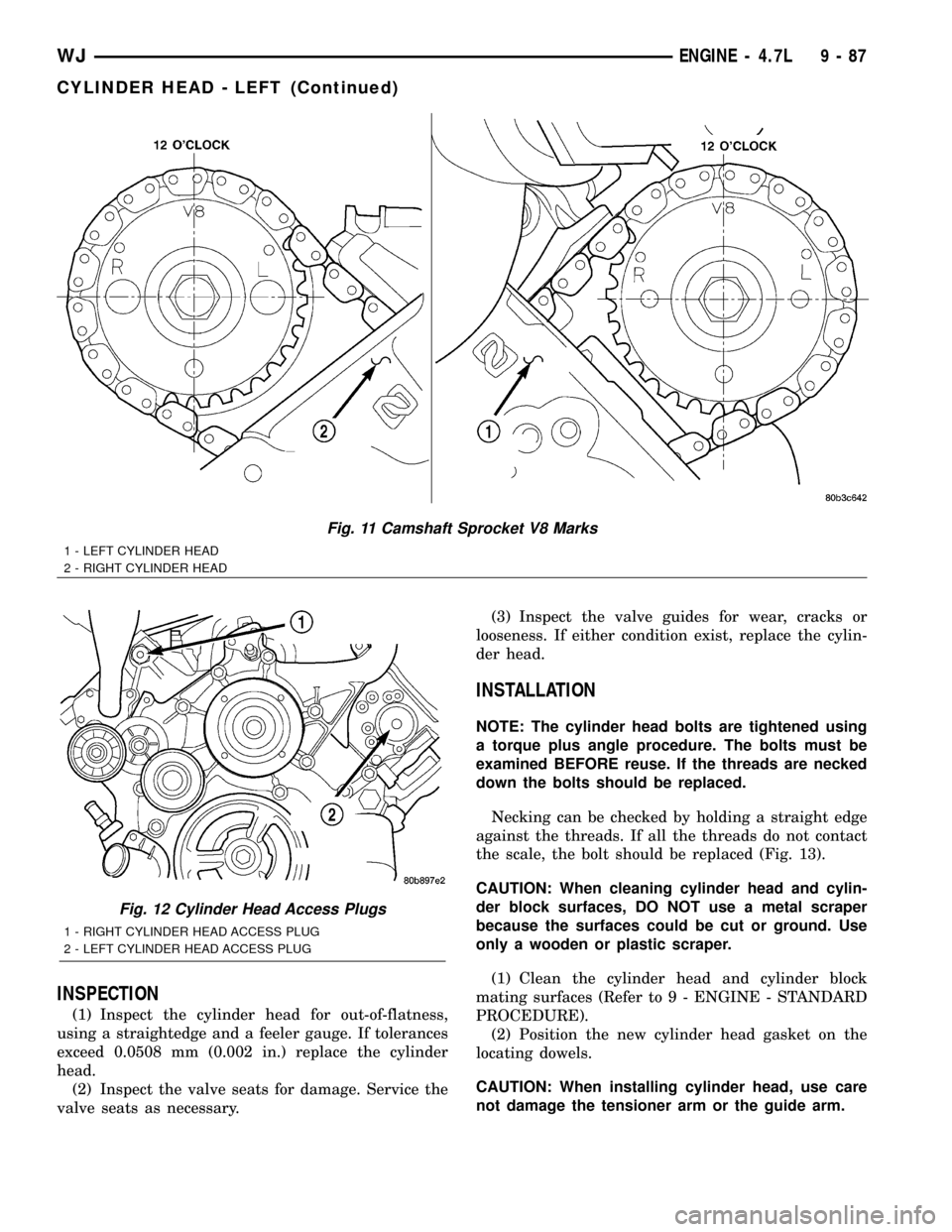
Fig. 11 Camshaft Sprocket V8 Marks
1 - LEFT CYLINDER HEAD
2 - RIGHT CYLINDER HEAD
Fig. 12 Cylinder Head Access Plugs
1 - RIGHT CYLINDER HEAD ACCESS PLUG
2 - LEFT CYLINDER HEAD ACCESS PLUG
WJENGINE - 4.7L 9 - 87
CYLINDER HEAD - LEFT (Continued)