2003 JEEP GRAND CHEROKEE camshaft torque
[x] Cancel search: camshaft torquePage 398 of 2199

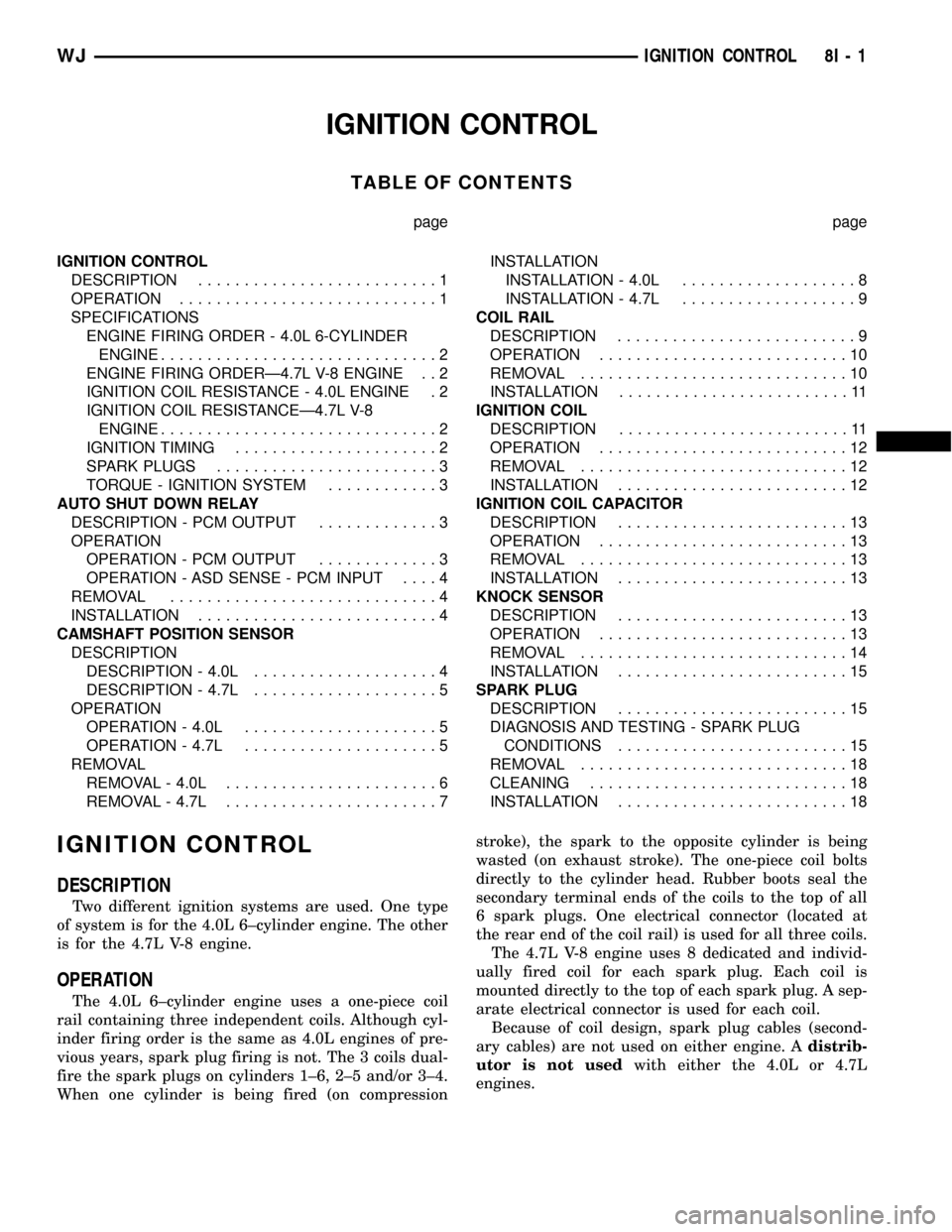
IGNITION CONTROL
TABLE OF CONTENTS
page page
IGNITION CONTROL
DESCRIPTION..........................1
OPERATION............................1
SPECIFICATIONS
ENGINE FIRING ORDER - 4.0L 6-CYLINDER
ENGINE..............................2
ENGINE FIRING ORDERÐ4.7L V-8 ENGINE . . 2
IGNITION COIL RESISTANCE - 4.0L ENGINE . 2
IGNITION COIL RESISTANCEÐ4.7L V-8
ENGINE..............................2
IGNITION TIMING......................2
SPARK PLUGS........................3
TORQUE - IGNITION SYSTEM............3
AUTO SHUT DOWN RELAY
DESCRIPTION - PCM OUTPUT.............3
OPERATION
OPERATION - PCM OUTPUT.............3
OPERATION - ASD SENSE - PCM INPUT....4
REMOVAL.............................4
INSTALLATION..........................4
CAMSHAFT POSITION SENSOR
DESCRIPTION
DESCRIPTION - 4.0L....................4
DESCRIPTION - 4.7L....................5
OPERATION
OPERATION - 4.0L.....................5
OPERATION - 4.7L.....................5
REMOVAL
REMOVAL - 4.0L.......................6
REMOVAL - 4.7L.......................7INSTALLATION
INSTALLATION - 4.0L...................8
INSTALLATION - 4.7L...................9
COIL RAIL
DESCRIPTION..........................9
OPERATION...........................10
REMOVAL.............................10
INSTALLATION.........................11
IGNITION COIL
DESCRIPTION.........................11
OPERATION...........................12
REMOVAL.............................12
INSTALLATION.........................12
IGNITION COIL CAPACITOR
DESCRIPTION.........................13
OPERATION...........................13
REMOVAL.............................13
INSTALLATION.........................13
KNOCK SENSOR
DESCRIPTION.........................13
OPERATION...........................13
REMOVAL.............................14
INSTALLATION.........................15
SPARK PLUG
DESCRIPTION.........................15
DIAGNOSIS AND TESTING - SPARK PLUG
CONDITIONS.........................15
REMOVAL.............................18
CLEANING............................18
INSTALLATION.........................18
IGNITION CONTROL
DESCRIPTION
Two different ignition systems are used. One type
of system is for the 4.0L 6±cylinder engine. The other
is for the 4.7L V-8 engine.
OPERATION
The 4.0L 6±cylinder engine uses a one-piece coil
rail containing three independent coils. Although cyl-
inder firing order is the same as 4.0L engines of pre-
vious years, spark plug firing is not. The 3 coils dual-
fire the spark plugs on cylinders 1±6, 2±5 and/or 3±4.
When one cylinder is being fired (on compressionstroke), the spark to the opposite cylinder is being
wasted (on exhaust stroke). The one-piece coil bolts
directly to the cylinder head. Rubber boots seal the
secondary terminal ends of the coils to the top of all
6 spark plugs. One electrical connector (located at
the rear end of the coil rail) is used for all three coils.
The 4.7L V-8 engine uses 8 dedicated and individ-
ually fired coil for each spark plug. Each coil is
mounted directly to the top of each spark plug. A sep-
arate electrical connector is used for each coil.
Because of coil design, spark plug cables (second-
ary cables) are not used on either engine. Adistrib-
utor is not usedwith either the 4.0L or 4.7L
engines.
WJIGNITION CONTROL 8I - 1
Page 400 of 2199

SPARK PLUGS
ENGINE PLUG TYPE ELECTRODE GAP
4.0L 6-CYL. RC12ECC 0.89 mm (.035 in.)
4.7L V-8 (Exc. HO) RC12MCC4 1.01 mm (.040 in.)
4.7L V-8 High
Output (HO)RC7PYCB4 1.01 mm (.040 in.)
TORQUE - IGNITION SYSTEM
DESCRIPTION N-m Ft. Lbs. In. Lbs.
Crankshaft Position Sensor
Bolts - 4.0L Engine7- 60
Crankshaft Position Sensor
Bolt - 4.7L V-8 Engine28 21 -
Camshaft Position
Sensor±to±base bolts - 4.0L
Engine2- 15
Camshaft Position Sensor
Bolt - 4.7L V-8 Engine12 - 106
Oil Pump Drive Hold-down
Bolt - 4.0L Engine23 17 -
Ignition Coil Rail Mounting
Bolts - 4.0L Engine29 - 250
Ignition Coil Mounting Nut -
4.7L V-8 Engine8- 70
* Knock Sensor Bolt - 4.7L
HO V-8 Engine*20 *15 -
Spark Plugs - 4.0L Engine 35-41 26-30 -
Spark Plugs - 4.7L V-8
Engine24-30 18-22 -
* Do not apply any sealant,
thread-locker or adhesive to
bolts. Poor sensor
performance may result.
Refer to Removal / Installation
for additional information.
AUTO SHUT DOWN RELAY
DESCRIPTION - PCM OUTPUT
The 5±pin, 12±volt, Automatic Shutdown (ASD)
relay is located in the Power Distribution Center
(PDC). Refer to label on PDC cover for relay location.
OPERATION
OPERATION - PCM OUTPUT
The ASD relay supplies battery voltage (12+ volts)
to the fuel injectors and ignition coil(s). With certain
emissions packages it also supplies 12±volts to the
oxygen sensor heating elements.
The ground circuit for the coil within the ASD
relay is controlled by the Powertrain Control Module
(PCM). The PCM operates the ASD relay by switch-
ing its ground circuit on and off.
WJIGNITION CONTROL 8I - 3
IGNITION CONTROL (Continued)
Page 405 of 2199

INSTALLATION
INSTALLATION - 4.0L
SENSOR ONLY - 4.0L
The Camshaft Position Sensor (CMP) on the 4.0L
6±cylinder engine is bolted to the top of the oil pump
drive shaft assembly (Fig. 6). The sensor and drive
shaft assembly is located on the right side of the
engine near the oil filter (Fig. 7).
(1) Install sensor to oil pump drive.
(2) Install 2 sensor mounting bolts and tighten to
2 N´m (15 in. lbs.) torque.
(3) Connect electrical connector to CMP sensor.
OIL PUMP DRIVE AND SENSOR - 4.0L
(1) Clean oil pump drive mounting hole area of
engine block.
(2) Install new oil pump drive-to-engine block gas-
ket.
(3) Temporarily install a toothpick or similar tool
through access hole at side of oil pump drive housing.
Align toothpick into mating hole on pulse ring (Fig.
8).(4) Install oil pump drive into engine while align-
ing into slot on oil pump. Rotate oil pump drive back
to its original position and install hold-down clamp
and bolt. Finger tighten bolt. Do not do a final tight-
ening of bolt at this time.
(5) If engine crankshaft or camshaft has been
rotated, such as during engine tear-down, CMP sen-
sor relationship must be reestablished.
(a) Remove ignition coil rail assembly. Refer to
Ignition Coil Removal/Installation.
(b) Remove cylinder number 1 spark plug.
(c) Hold a finger over the open spark plug hole.
Rotate engine at vibration dampener bolt until
compression (pressure) is felt.
(d) Slowly continue to rotate engine. Do this
until timing index mark on vibration damper pul-
ley aligns with top dead center (TDC) mark (0
degree) on timing degree scale (Fig. 9). Always
rotate engine in direction of normal rotation. Do
not rotate engine backward to align timing marks.
(e) Install oil pump drive into engine while
aligning into slot on oil pump. If pump drive will
not drop down flush to engine block, the oil pump
slot is not aligned. Remove oil pump drive and
align slot in oil pump to shaft at bottom of drive.
Install into engine. Rotate oil pump drive back to
its original position and install hold-down clamp
and bolt. Finger tighten bolt. Do not do a final
tightening of bolt at this time.
(f) Remove toothpick from housing.
(6) Install sensor to oil pump drive. After installa-
tion, the CMP sensor should face rear of engine 0É.
(7) Install 2 sensor mounting bolts and tighten to
2 N´m (15 in. lbs.) torque.
(8) Connect electrical connector to CMP sensor.
(9) If removed, install spark plug and ignition coil
rail.
To verify correct rotational position of oil pump
drive, the DRB scan tool must be used.
WARNING: WHEN PERFORMING THE FOLLOWING
TEST, THE ENGINE WILL BE RUNNING. BE CARE-
FUL NOT TO STAND IN LINE WITH THE FAN
BLADES OR FAN BELT. DO NOT WEAR LOOSE
CLOTHING.
(10) Connect DRB scan tool to data link connector.
The data link connector is located in passenger com-
partment, below and to left of steering column.
(11) Gain access to SET SYNC screen on DRB.
(12) Follow directions on DRB screen and start
engine. Bring to operating temperature (engine must
be in ªclosed loopº mode).
(13) With engine running atidle speed, the words
IN RANGE should appear on screen along with 0É.
This indicates correct position of oil pump drive.
Fig. 10 CMP LocationÐ4.7L Engine
1 - RIGHT CYLINDER HEAD
2 - CAMSHAFT POSITION SENSOR
3 - MOUNTING BOLT
4 - ELEC. CONNECTOR
8I - 8 IGNITION CONTROLWJ
CAMSHAFT POSITION SENSOR (Continued)
Page 406 of 2199

(14) If a plus (+) or a minus (-) is displayed next to
degree number, and/or the degree displayed is not
zero, loosen but do not remove hold-down clamp bolt.
Rotate oil pump drive until IN RANGE appears on
screen. Continue to rotate oil pump drive until
achieving as close to 0É as possible.
The degree scale on SET SYNC screen of DRB is
referring to fuel synchronization only.It is not
referring to ignition timing.Because of this, do
not attempt to adjust ignition timing using this
method. Rotating oil pump drive will have no effect
on ignition timing. All ignition timing values are con-
trolled by powertrain control module (PCM).
(15) Tighten hold-down clamp bolt to 23 N´m (17
ft. lbs.) torque.
INSTALLATION - 4.7L
The Camshaft Position Sensor (CMP) on the 4.7L
V±8 engine is bolted to the front/top of the right cyl-
inder head (Fig. 10).
(1) Clean out machined hole in cylinder head.
(2) Apply a small amount of engine oil to sensor
o-ring.
(3) Install sensor into cylinder head with a slight
rocking action. Do not twist sensor into position as
damage to o-ring may result.
CAUTION: Before tightening sensor mounting bolt,
be sure sensor is completely flush to cylinder head.
If sensor is not flush, damage to sensor mounting
tang may result.
(4) Install mounting bolt and tighten to 12 N´m
(106 in. lbs.) torque.
(5) Connect electrical connector to sensor.
(6) Lower vehicle.
COIL RAIL
DESCRIPTION
A one-piece coil rail assembly containing three
individual coils is used on the 4.0L 6±cylinder engine
(Fig. 11). The coil rail must be replaced as one
assembly. The bottom of the coil is equipped with 6
individual rubber boots (Fig. 11) to seal the 6 spark
plugs to the coil. Inside each rubber boot is a spring.
The spring is used for a mechanical contact between
the coil and the top of the spark plug. These rubber
boots and springs are a permanent part of the coil
and are not serviced separately.
(1) The coil is bolted directly to the cylinder head
(Fig. 12). One electrical connector (located at rear of
coil) is used for all three coils.
Fig. 11 Ignition Coil AssemblyÐ4.0L 6±Cylinder
Engine
1 - CYL. #6
2 - CYL. #5
3 - CYL. #4
4 - CYL. #3
5 - CYL. #2
6 - CYL. #1
7 - COILS (3)
8 - MOUNTING BOLTS (4)
9 - BOLT BASES (4)
10 - RUBBER BOOTS (6)
Fig. 12 Coil LocationÐ4.0L Engine
1 - COIL RAIL
2 - COIL MOUNTING BOLTS (4)
3 - COIL
4 - COIL ELECTRICAL CONNECTION
WJIGNITION CONTROL 8I - 9
CAMSHAFT POSITION SENSOR (Continued)
Page 1244 of 2199

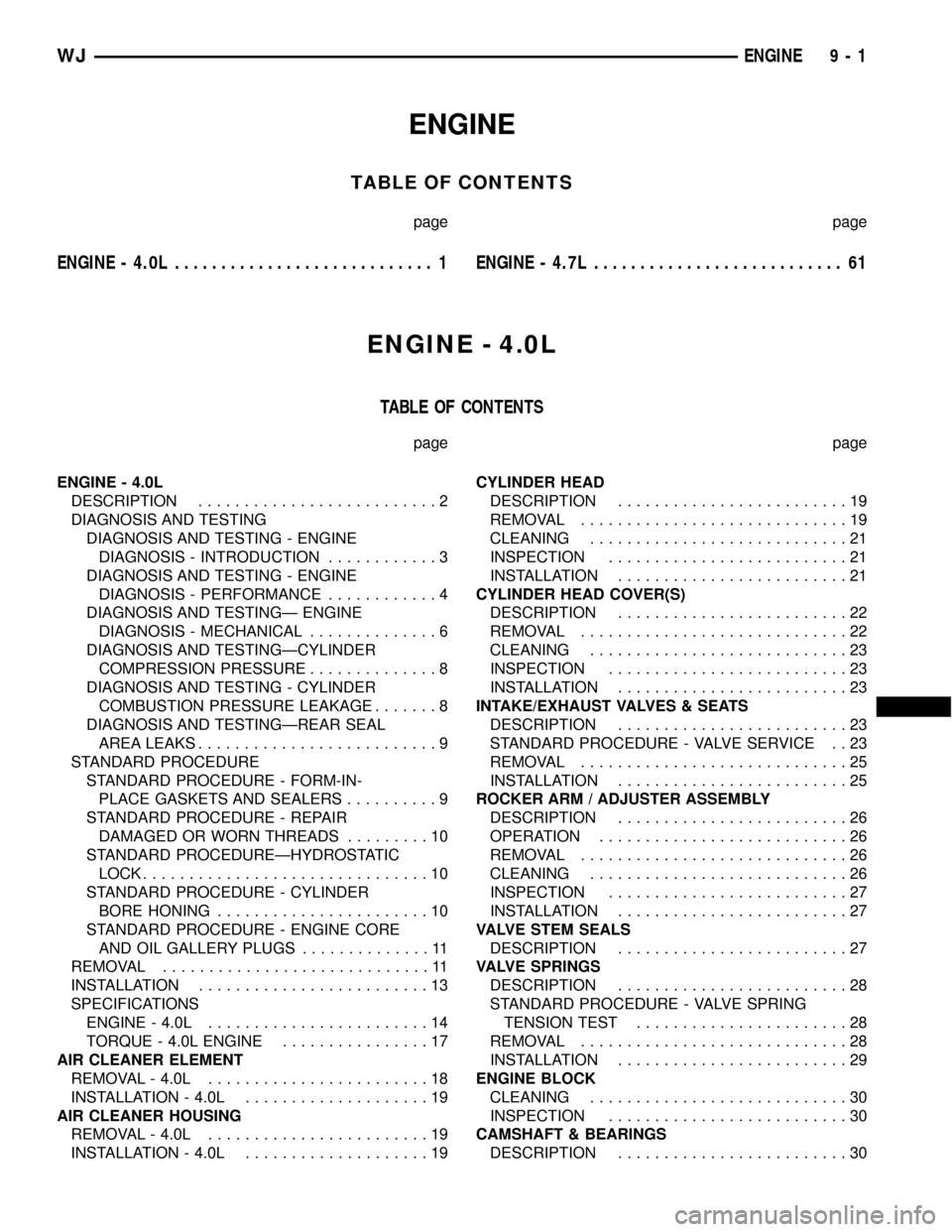
ENGINE
TABLE OF CONTENTS
page page
ENGINE - 4.0L............................ 1ENGINE - 4.7L........................... 61
ENGINE - 4.0L
TABLE OF CONTENTS
page page
ENGINE - 4.0L
DESCRIPTION..........................2
DIAGNOSIS AND TESTING
DIAGNOSIS AND TESTING - ENGINE
DIAGNOSIS - INTRODUCTION............3
DIAGNOSIS AND TESTING - ENGINE
DIAGNOSIS - PERFORMANCE............4
DIAGNOSIS AND TESTINGÐ ENGINE
DIAGNOSIS - MECHANICAL..............6
DIAGNOSIS AND TESTINGÐCYLINDER
COMPRESSION PRESSURE..............8
DIAGNOSIS AND TESTING - CYLINDER
COMBUSTION PRESSURE LEAKAGE.......8
DIAGNOSIS AND TESTINGÐREAR SEAL
AREA LEAKS..........................9
STANDARD PROCEDURE
STANDARD PROCEDURE - FORM-IN-
PLACE GASKETS AND SEALERS..........9
STANDARD PROCEDURE - REPAIR
DAMAGED OR WORN THREADS.........10
STANDARD PROCEDUREÐHYDROSTATIC
LOCK...............................10
STANDARD PROCEDURE - CYLINDER
BORE HONING.......................10
STANDARD PROCEDURE - ENGINE CORE
AND OIL GALLERY PLUGS..............11
REMOVAL.............................11
INSTALLATION.........................13
SPECIFICATIONS
ENGINE - 4.0L........................14
TORQUE - 4.0L ENGINE................17
AIR CLEANER ELEMENT
REMOVAL - 4.0L........................18
INSTALLATION - 4.0L....................19
AIR CLEANER HOUSING
REMOVAL - 4.0L........................19
INSTALLATION - 4.0L....................19CYLINDER HEAD
DESCRIPTION.........................19
REMOVAL.............................19
CLEANING............................21
INSPECTION..........................21
INSTALLATION.........................21
CYLINDER HEAD COVER(S)
DESCRIPTION.........................22
REMOVAL.............................22
CLEANING............................23
INSPECTION..........................23
INSTALLATION.........................23
INTAKE/EXHAUST VALVES & SEATS
DESCRIPTION.........................23
STANDARD PROCEDURE - VALVE SERVICE . . 23
REMOVAL.............................25
INSTALLATION.........................25
ROCKER ARM / ADJUSTER ASSEMBLY
DESCRIPTION.........................26
OPERATION...........................26
REMOVAL.............................26
CLEANING............................26
INSPECTION..........................27
INSTALLATION.........................27
VALVE STEM SEALS
DESCRIPTION.........................27
VALVE SPRINGS
DESCRIPTION.........................28
STANDARD PROCEDURE - VALVE SPRING
TENSION TEST.......................28
REMOVAL.............................28
INSTALLATION.........................29
ENGINE BLOCK
CLEANING............................30
INSPECTION..........................30
CAMSHAFT & BEARINGS
DESCRIPTION.........................30
WJENGINE 9 - 1
Page 1252 of 2199

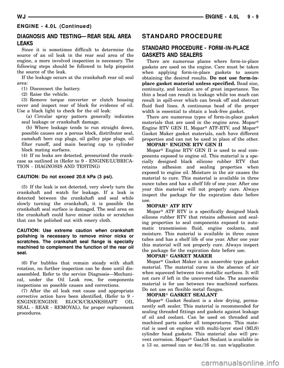
DIAGNOSIS AND TESTINGÐREAR SEAL AREA
LEAKS
Since it is sometimes difficult to determine the
source of an oil leak in the rear seal area of the
engine, a more involved inspection is necessary. The
following steps should be followed to help pinpoint
the source of the leak.
If the leakage occurs at the crankshaft rear oil seal
area:
(1) Disconnect the battery.
(2) Raise the vehicle.
(3) Remove torque converter or clutch housing
cover and inspect rear of block for evidence of oil.
Use a black light to check for the oil leak:
(a) Circular spray pattern generally indicates
seal leakage or crankshaft damage.
(b) Where leakage tends to run straight down,
possible causes are a porous block, distributor seal,
camshaft bore cup plugs, oil galley pipe plugs, oil
filter runoff, and main bearing cap to cylinder
block mating surfaces.
(4) If no leaks are detected, pressurized the crank-
case as outlined in (Refer to 9 - ENGINE/LUBRICA-
TION - DIAGNOSIS AND TESTING)
CAUTION: Do not exceed 20.6 kPa (3 psi).
(5) If the leak is not detected, very slowly turn the
crankshaft and watch for leakage. If a leak is
detected between the crankshaft and seal while
slowly turning the crankshaft, it is possible the
crankshaft seal surface is damaged. The seal area on
the crankshaft could have minor nicks or scratches
that can be polished out with emery cloth.
CAUTION: Use extreme caution when crankshaft
polishing is necessary to remove minor nicks or
scratches. The crankshaft seal flange is specially
machined to complement the function of the rear oil
seal.
(6) For bubbles that remain steady with shaft
rotation, no further inspection can be done until dis-
assembled. Refer to the service DiagnosisÐMechani-
cal, under the Oil Leak row, for components
inspections on possible causes and corrections.
(7) After the oil leak root cause and appropriate
corrective action have been identified, (Refer to 9 -
ENGINE/ENGINE BLOCK/CRANKSHAFT OIL
SEAL - REAR - REMOVAL), for proper replacement
procedures.
STANDARD PROCEDURE
STANDARD PROCEDURE - FORM-IN-PLACE
GASKETS AND SEALERS
There are numerous places where form-in-place
gaskets are used on the engine. Care must be taken
when applying form-in-place gaskets to assure
obtaining the desired results.Do not use form-in-
place gasket material unless specified.Bead size,
continuity, and location are of great importance. Too
thin a bead can result in leakage while too much can
result in spill-over which can break off and obstruct
fluid feed lines. A continuous bead of the proper
width is essential to obtain a leak-free gasket.
There are numerous types of form-in-place gasket
materials that are used in the engine area. Mopart
Engine RTV GEN II, MopartATF-RTV, and Mopart
Gasket Maker gasket materials, each have different
properties and can not be used in place of the other.
MOPARtENGINE RTV GEN II
MopartEngine RTV GEN II is used to seal com-
ponents exposed to engine oil. This material is a spe-
cially designed black silicone rubber RTV that
retains adhesion and sealing properties when
exposed to engine oil. Moisture in the air causes the
material to cure. This material is available in three
ounce tubes and has a shelf life of one year. After one
year this material will not properly cure. Always
inspect the package for the expiration date before
use.
MOPARtATF RTV
MopartATF RTV is a specifically designed black
silicone rubber RTV that retains adhesion and seal-
ing properties to seal components exposed to auto-
matic transmission fluid, engine coolants, and
moisture. This material is available in three ounce
tubes and has a shelf life of one year. After one year
this material will not properly cure. Always inspect
the package for the expiration date before use.
MOPARtGASKET MAKER
MopartGasket Maker is an anaerobic type gasket
material. The material cures in the absence of air
when squeezed between two metallic surfaces. It will
not cure if left in the uncovered tube. The anaerobic
material is for use between two machined surfaces.
Do not use on flexible metal flanges.
MOPARtGASKET SEALANT
MopartGasket Sealant is a slow drying, perma-
nently soft sealer. This material is recommended for
sealing threaded fittings and gaskets against leakage
of oil and coolant. Can be used on threaded and
machined parts under all temperatures. This mate-
rial is used on engines with multi-layer steel (MLS)
cylinder head gaskets. This material also will pre-
vent corrosion. MopartGasket Sealant is available in
a 13 oz. aerosol can or 4oz./16 oz. can w/applicator.
WJENGINE - 4.0L 9 - 9
ENGINE - 4.0L (Continued)
Page 1256 of 2199

INSTALLATION
CAUTION: When installing the engine into a vehicle
equipped with an automatic transmission, be care-
ful not to damage the trigger wheel on the engine
flywheel.
(1) Attach a lifting device to the engine and lower
the engine into the engine compartment. For easier
installation, it may be necessary to remove the
engine mount bracket as an aid in alignment of the
engine to the transmission.
(2) Align the transmission torque converter hous-
ing with the engine.
(3) Loosely install the converter housing lower
bolts and install the next higher bolt and nut on each
side.
(4) Tighten all 4 bolts finger tight.
(5) Install the engine mount brackets (if removed).
(6) Lower the engine and engine mount brackets
onto the engine compartment cushions. Install the
bolts and finger tighten the nuts.
(7) Remove the engine lifting device.
(8) Raise and support the vehicle.
(9) Install the remaining engine flywheel/converter
housing bolts. Tighten all bolts to 38 N´m (28 ft. lbs.)
torque.
(10) Install the converter-to-drive plate bolts.
(11) Ensure the installation reference marks are
aligned.
(12) Install the engine flywheel/converter housing
access cover.
(13) Install the exhaust pipe support and tighten
the screw.
(14) Install the engine bending brace (Refer to 9 -
ENGINE/ENGINE BLOCK/STRUCT SUPPORT -
INSTALLATION).
(15) Tighten the engine mount-to-bracket bolts.
(16) Connect the vehicle speed sensor wire connec-
tions and tighten the screws.
(17) Connect the exhaust pipe to the manifold.
(18) Install the engine starter motor (Refer to 8 -
ELECTRICAL/STARTING/STARTER MOTOR -
INSTALLATION).
(19) Connect the wires to the engine starter motor
solenoid.
(20) Lower the vehicle.
(21) Connect all the vacuum hoses and wire con-
nectors identified during engine removal.
(22) Remove protective caps from the power steer-
ing hoses.
(23) Connect the hoses to the fittings at the steer-
ing gear. Tighten the nut to 52 N´m (38 ft. lbs.)
torque.
(24) Fill the pump reservoir with fluid.(25) Inspect the fuel supply line o-ring(s) and
replace if necessary. Connect fuel supply line to injec-
tior rail and verify connection by pulling outward on
the line.
(26) Install the fuel line bracket to the intake
manifold.
(27) Connect the coil rail electrical connectors and
oil pressure switch connector.
(28) Connect the following electrical connectors:
²Power steering pressure switch
²Coolant temperature sensor
²Six (6) fuel injector connectors
²Intake air temperature sensor
²Throttle position sensor
²Map sensor
²Crankshaft position sensor
²Oxygen sensor
²Camshaft position sensor
²Generator connector and B+ terminal wire
(29) Connect all previously removed vacuum hoses.
(30) Connect the body ground strap.
(31) Install the throttle, transmission line pres-
sure, and speed control cables to their mounting
bracket and connect them to the throttle body.
(32) Connect the heater hoses at the engine ther-
mostat housing and water pump.
(33) Install the fan assembly (Refer to 7 - COOL-
ING/ENGINE/RADIATOR FAN - INSTALLATION).
(34) Place the fan shroud in position over the fan.
(35) Install the radiator (Refer to 7 - COOLING/
ENGINE/RADIATOR - INSTALLATION).
(36) Connect the service valves to the A/C com-
pressor ports, if equipped with A/C.
(37) Charge the air conditioner system (Refer to 24
- HEATING & AIR CONDITIONING/PLUMBING -
STANDARD PROCEDURE).
(38) Connect the radiator hoses and automatic
transmission fluid cooler pipes, if equipped.
(39) Install the fan shroud to the radiator or radi-
ator/condenser (if equipped with A/C).
(40) Install upper radiator support.
(41) Connect the upper radiator hose and tighten
the clamp.
(42) Connect the lower radiator hose and tighten
the clamp.
(43) Fill crankcase with engine oil. (Refer to
LUBRICATION & MAINTENANCE/FLUID CAPACI-
TIES - SPECIFICATIONS) for correct capacities.
(44) Fill the cooling system with reusable coolant
or new coolant (Refer to 7 - COOLING - STANDARD
PROCEDURE).
(45) Align the hood to the scribe marks. Install the
hood.
(46) Install the air cleaner assembly.
(47) Install the battery and connect the battery
cable.
WJENGINE - 4.0L 9 - 13
ENGINE - 4.0L (Continued)
Page 1260 of 2199

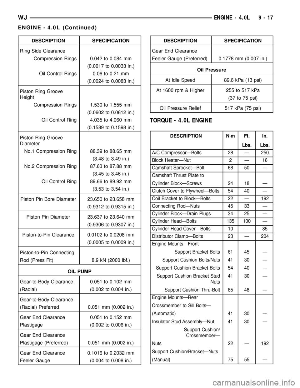
DESCRIPTION SPECIFICATION
Ring Side Clearance
Compression Rings 0.042 to 0.084 mm
(0.0017 to 0.0033 in.)
Oil Control Rings 0.06 to 0.21 mm
(0.0024 to 0.0083 in.)
Piston Ring Groove
Height
Compression Rings 1.530 to 1.555 mm
(0.0602 to 0.0612 in.)
Oil Control Ring 4.035 to 4.060 mm
(0.1589 to 0.1598 in.)
Piston Ring Groove
Diameter
No.1 Compression Ring 88.39 to 88.65 mm
(3.48 to 3.49 in.)
No.2 Compression Ring 87.63 to 87.88 mm
(3.45 to 3.46 in.)
Oil Control Ring 89.66 to 89.92 mm
(3.53 to 3.54 in.)
Piston Pin Bore Diameter 23.650 to 23.658 mm
(0.9312 to 0.9315 in.)
Piston Pin Diameter 23.637 to 23.640 mm
(0.9306 to 0.9307 in.)
Piston-to-Pin Clearance 0.0102 to 0.0208 mm
(0.0005 to 0.0009 in.)
Piston-to-Pin Connecting
Rod (Press Fit) 8.9 kN (2000 lbf.)
OIL PUMP
Gear-to-Body Clearance 0.051 to 0.102 mm
(Radial) (0.002 to 0.004 in.)
Gear-to-Body Clearance
(Radial) Preferred 0.051 mm (0.002 in.)
Gear End Clearance 0.051 to 0.152 mm
Plastigage (0.002 to 0.006 in.)
Gear End Clearance
Plastigage (Preferred) 0.051 mm (0.002 in.)
Gear End Clearance 0.1016 to 0.2032 mm
Feeler Gauge (0.004 to 0.008 in.)DESCRIPTION SPECIFICATION
Gear End Clearance
Feeler Gauge (Preferred) 0.1778 mm (0.007 in.)
Oil Pressure
At Idle Speed 89.6 kPa (13 psi)
At 1600 rpm & Higher 255 to 517 kPa
(37 to 75 psi)
Oil Pressure Relief 517 kPa (75 psi)
TORQUE - 4.0L ENGINE
DESCRIPTION N´m Ft. In.
Lbs. Lbs.
A/C CompressorÐBolts 28 Ð 250
Block HeaterÐNut 2 Ð 16
Camshaft SprocketÐBolt 68 50 Ð
Camshaft Thrust Plate to
Cylinder BlockÐScrews 24 18 Ð
Clutch Cover to FlywheelÐBolts 54 40 Ð
Coil Bracket to BlockÐBolts 22 Ð 192
Connecting RodÐNuts 45 33 Ð
Cylinder BlockÐDrain Plugs 34 25 Ð
Cylinder HeadÐBolts 135 100 Ð
Cylinder Head CoverÐBolts 10 Ð 85
Distributor ClampÐBolts 23 Ð 204
Engine MountsÐFront
Support Bracket Bolts 61 45 Ð
Support Cushion Bolts/Nuts 41 30 Ð
Support Cushion Bracket Bolts 54 40 Ð
Support Cushion Bracket Stud
Nuts41 30 Ð
Support Cushion Thru-Bolt 65 48 Ð
Engine MountsÐRear
Crossmember to Sill BoltsÐ
(Automatic) 41 30 Ð
Insulator Stud AssemblyÐNut 41 30 Ð
Support Cushion/
CrossmemberÐ
Nuts 22 Ð 192
Support Cushion/BracketÐNuts
(Manual) 75 55 Ð
WJENGINE - 4.0L 9 - 17
ENGINE - 4.0L (Continued)