2003 JEEP GRAND CHEROKEE differential
[x] Cancel search: differentialPage 1826 of 2199

NV242HD REAR RETAINER
(1) Apply bead of MopartSealer, or LoctiteŸ
Ultra Gray, to mating surface of rear retainer. Sealer
bead should be a maximum of 3/16 in.
(2) Install rear retainer on rear case. Tighten
retainer bolts to 20-27 N´m (15-20 ft. lbs.) torque.
(3) Install new output shaft bearing snap-ring
(Fig. 91). Lift mainshaft slightly to seat snap-ring in
shaft groove, if necessary.
(4) Apply 3 mm (1/8 in.) wide bead of Mopartgas-
ket maker or silicone adhesive sealer to mounting
surface of extension housing. Allow sealer to set-up
slightly before proceeding.(5) Install extension housing on rear retainer.
(6) Install extension housing bolts and tighten to
35-46 N´m (26-34 ft. lbs.).
COMPANION FLANGE
(1) Lubricate companion flange hub with transmis-
sion fluid and install flange on front shaft.
(2) Install new seal washer on front shaft.
(3) Install flange on front shaft and tighten nut to
122-176 N´m (90-130 ft. lbs.).
INSTALLATION
(1) Mount transfer case on a transmission jack.
(2) Secure transfer case to jack with chains.
(3) Position transfer case under vehicle.
(4) Align transfer case and transmission shafts
and install transfer case on transmission.
(5) Install and tighten transfer case attaching nuts
to 35 N´m (26 ft. lbs.) torque (Fig. 4).
(6) Align and connect propeller shafts. (Refer to 3 -
DIFFERENTIAL & DRIVELINE/PROPELLER
SHAFT/PROPELLER SHAFT - INSTALLATION)
(7) Fill transfer case with correct fluid. Check
transmission fluid level. Correct as necessary.
(8) Install rear crossmember and skid plate, if
equipped. Tighten crossmember bolts to 41 N´m (30
ft. lbs.) torque.
(9) Remove transmission jack and support stand.
(10) Connect shift rod to transfer case range lever.
(11) Connect transfer case vent hose and transfer
case position sensor.
(12) Adjust transfer case shift cable.
(13) Lower vehicle and verify transfer case shift
operation.
Fig. 91 Install Output Bearing Snap-ring
1 - REAR RETAINER
2 - SNAP-RING
3 - REAR BEARING
WJTRANSFER CASE - NV242 21 - 307
TRANSFER CASE - NV242 (Continued)
Page 1832 of 2199

(5) Install the rear propeller shaft. (Refer to 3 -
DIFFERENTIAL & DRIVELINE/PROPELLER
SHAFT/PROPELLER SHAFT - INSTALLATION)
(6) Verify proper fluid level.
(7) Lower vehicle.
SHIFT CABLE
REMOVAL
(1) Shift transfer case into NEUTRAL.
(2) Raise vehicle.
(3) Disconnect the shift cable eyelet from the
transfer case shift lever (Fig. 101).
(4) Remove shift cable from the cable support
bracket.
(5) Lower vehicle.
(6) Remove any necessary console parts for access
to shift lever assembly and shift cable.(7) Disconnect cable at shift lever and shifter
assembly bracket (Fig. 102).
(8) Remove the nuts holding the shift cable seal
plate to the floor pan (Fig. 103).
(9) Pull cable through floor panel opening.
(10) Remove transfer case shift cable from vehicle.
INSTALLATION
(1) Route cable through hole in floor pan.
(2) Install seal plate to studs in floor pan.
(3) Install nuts to hold seal plate to floor pan (Fig.
103). Tighten nuts to 7 N´m (65 in.lbs.).
Fig. 100 Install Rear Retainer Seal
1 - SPECIAL TOOL C-4171
2 - SPECIAL TOOL C-3995-A
Fig. 101 Transfer Case Shift Cable at Transfer Case
1 - TRANSFER CASE SHIFT LEVER
2 - TRANSFER CASE SHIFT CABLE
Fig. 102 Transfer Case Shift Cable at Shifter
1 - CLIP
2 - SHIFTER
3 - TRANSFER CASE SHIFT LEVER PIN
4 - TRANSFER CASE SHIFT CABLE
Fig. 103 Shift Cables at Floor Pan
1 - SEAL PLATES
2 - TRANSMISSION SHIFT CABLE
3 - TRANSFER CASE SHIFT CABLE
WJTRANSFER CASE - NV242 21 - 313
REAR RETAINER BUSHING AND SEAL - NV242HD (Continued)
Page 1835 of 2199

OPERATION
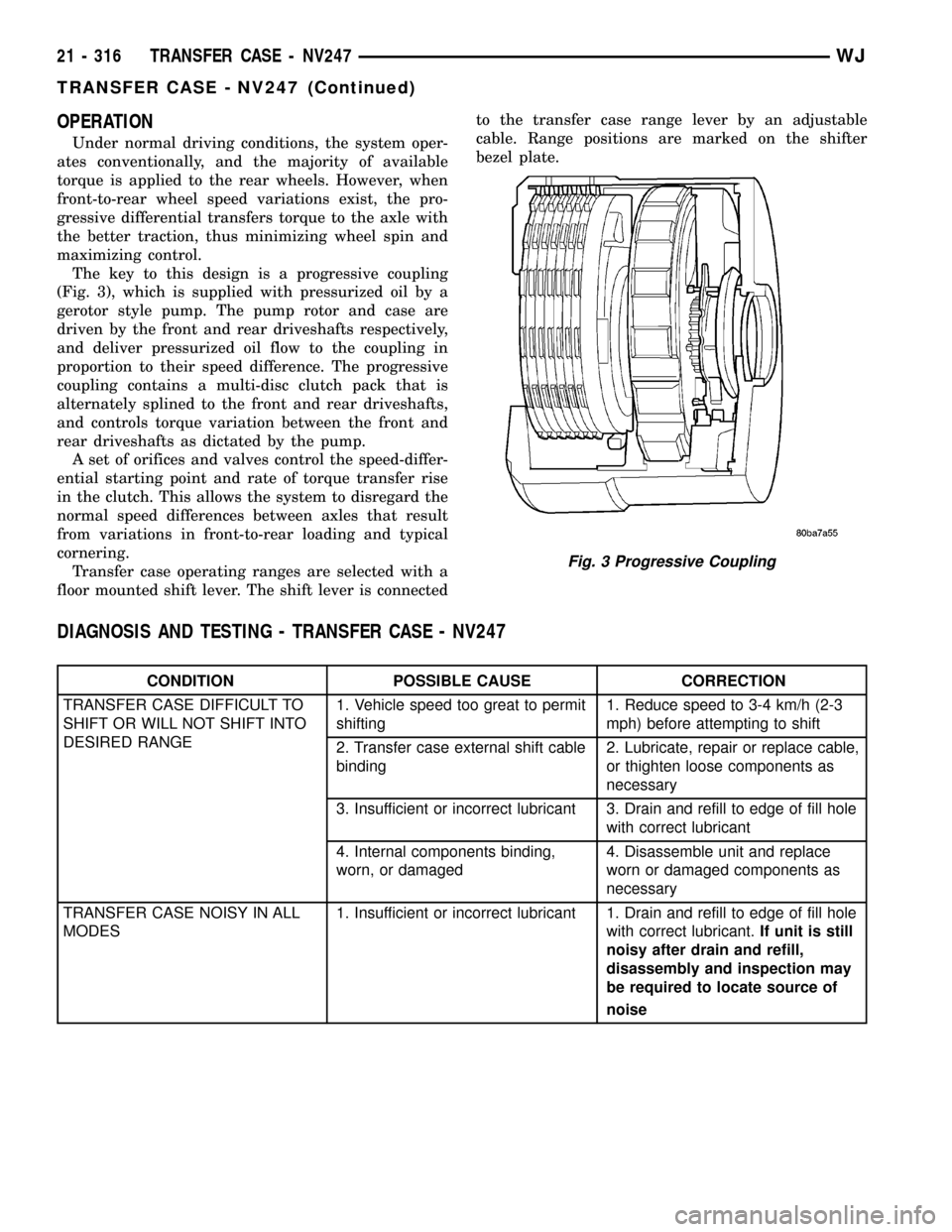
Under normal driving conditions, the system oper-
ates conventionally, and the majority of available
torque is applied to the rear wheels. However, when
front-to-rear wheel speed variations exist, the pro-
gressive differential transfers torque to the axle with
the better traction, thus minimizing wheel spin and
maximizing control.
The key to this design is a progressive coupling
(Fig. 3), which is supplied with pressurized oil by a
gerotor style pump. The pump rotor and case are
driven by the front and rear driveshafts respectively,
and deliver pressurized oil flow to the coupling in
proportion to their speed difference. The progressive
coupling contains a multi-disc clutch pack that is
alternately splined to the front and rear driveshafts,
and controls torque variation between the front and
rear driveshafts as dictated by the pump.
A set of orifices and valves control the speed-differ-
ential starting point and rate of torque transfer rise
in the clutch. This allows the system to disregard the
normal speed differences between axles that result
from variations in front-to-rear loading and typical
cornering.
Transfer case operating ranges are selected with a
floor mounted shift lever. The shift lever is connectedto the transfer case range lever by an adjustable
cable. Range positions are marked on the shifter
bezel plate.
DIAGNOSIS AND TESTING - TRANSFER CASE - NV247
CONDITION POSSIBLE CAUSE CORRECTION
TRANSFER CASE DIFFICULT TO
SHIFT OR WILL NOT SHIFT INTO
DESIRED RANGE1. Vehicle speed too great to permit
shifting1. Reduce speed to 3-4 km/h (2-3
mph) before attempting to shift
2. Transfer case external shift cable
binding2. Lubricate, repair or replace cable,
or thighten loose components as
necessary
3. Insufficient or incorrect lubricant 3. Drain and refill to edge of fill hole
with correct lubricant
4. Internal components binding,
worn, or damaged4. Disassemble unit and replace
worn or damaged components as
necessary
TRANSFER CASE NOISY IN ALL
MODES1. Insufficient or incorrect lubricant 1. Drain and refill to edge of fill hole
with correct lubricant.If unit is still
noisy after drain and refill,
disassembly and inspection may
be required to locate source of
noise
Fig. 3 Progressive Coupling
21 - 316 TRANSFER CASE - NV247WJ
TRANSFER CASE - NV247 (Continued)
Page 1836 of 2199

CONDITION POSSIBLE CAUSE CORRECTION
NOISY INÐOR JUMPS OUT OF
4WD LOW RANGE1. Transfer case not completely
engaged in 4WD LOW (possibly
from shift to 4L while rolling)1. Stop vehicle, shift transfer case
to neutral, then shift back to 4WD
LOW
2. Shift linkage loose, binding, or is
misadjusted2. Tighten, lubricate, or repair
linkage as necessary. Adjust linkage
if necessary
3. Range fork cracked, inserts
worn, or fork is binding on shift rail3. Disassemble unit and repair as
necessary
4. Annulus gear or lockplate worn
or damaged4. Disassemble unit and repair as
necessary
LUBRICANT LEAKING FROM
OUTPUT SHAFT SEALS OR FROM
VENT1. Transfer case over filled 1. Drain to correct level
2. Vent closed or restricted 2. Clear or replace vent if necessary
3. Output shaft seals damaged or
installed correctly3. Replace seals. Be sure seal lip
faces interior of case when installed.
Also be sure yoke seal surfaces are
not scored or nicked. Remove
scores and nicks with fine
sandpaper or replace yoke(s) if
necessary.
REMOVAL
(1) Shift transfer case into NEUTRAL.
(2) Raise vehicle.
(3) Remove transfer case drain plug and drain
transfer case lubricant.
(4) Mark front and rear propeller shaft yokes for
alignment reference.
(5) Support transmission with jack stand.
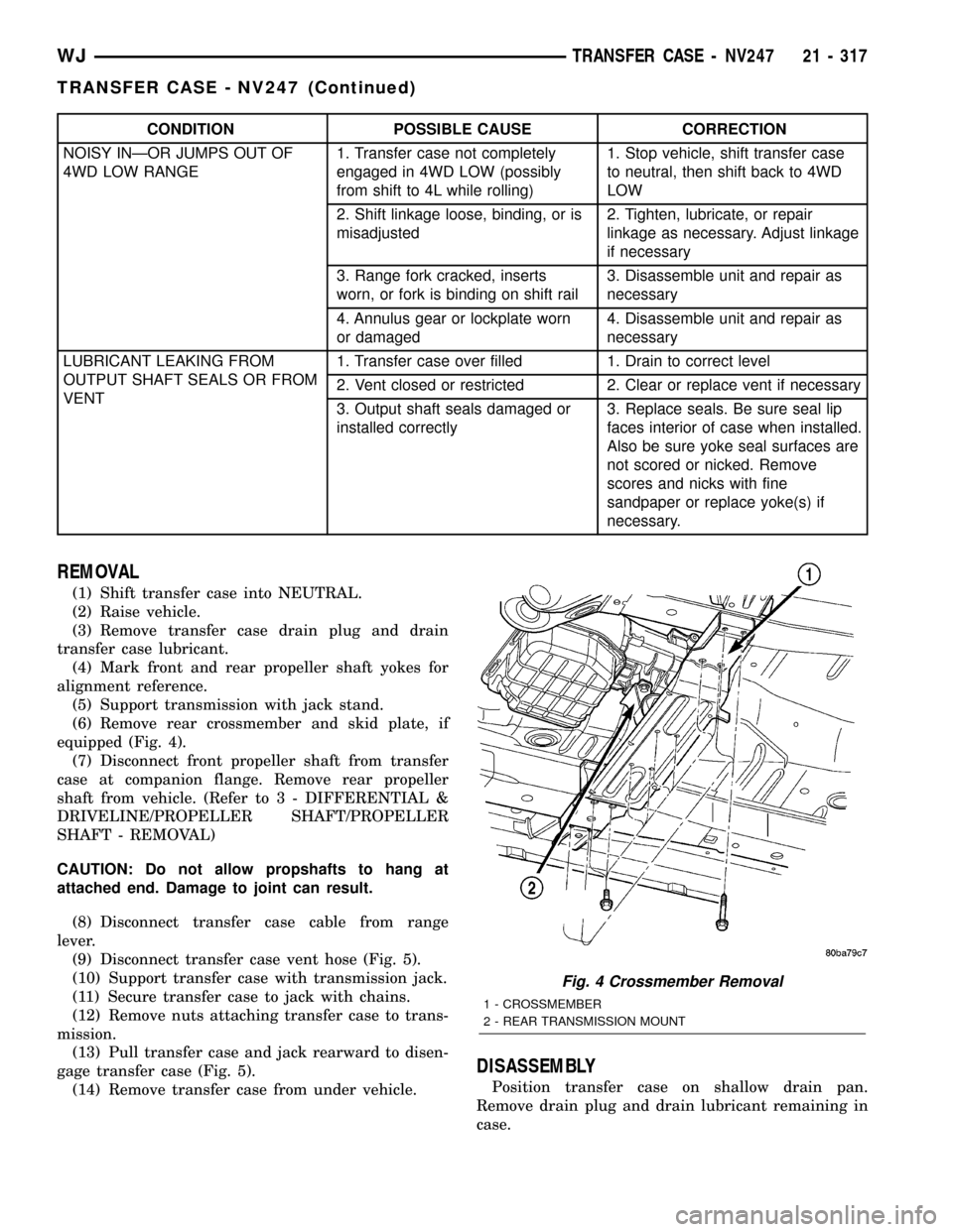
(6) Remove rear crossmember and skid plate, if
equipped (Fig. 4).
(7) Disconnect front propeller shaft from transfer
case at companion flange. Remove rear propeller
shaft from vehicle. (Refer to 3 - DIFFERENTIAL &
DRIVELINE/PROPELLER SHAFT/PROPELLER
SHAFT - REMOVAL)
CAUTION: Do not allow propshafts to hang at
attached end. Damage to joint can result.
(8) Disconnect transfer case cable from range
lever.
(9) Disconnect transfer case vent hose (Fig. 5).
(10) Support transfer case with transmission jack.
(11) Secure transfer case to jack with chains.
(12) Remove nuts attaching transfer case to trans-
mission.
(13) Pull transfer case and jack rearward to disen-
gage transfer case (Fig. 5).
(14) Remove transfer case from under vehicle.
DISASSEMBLY
Position transfer case on shallow drain pan.
Remove drain plug and drain lubricant remaining in
case.
Fig. 4 Crossmember Removal
1 - CROSSMEMBER
2 - REAR TRANSMISSION MOUNT
WJTRANSFER CASE - NV247 21 - 317
TRANSFER CASE - NV247 (Continued)
Page 1855 of 2199

(6) Connect front propeller shaft and install rear
propeller shaft. (Refer to 3 - DIFFERENTIAL &
DRIVELINE/PROPELLER SHAFT/PROPELLER
SHAFT - INSTALLATION)
(7) Fill transfer case with correct fluid. Check
transmission fluid level. Correct as necessary.
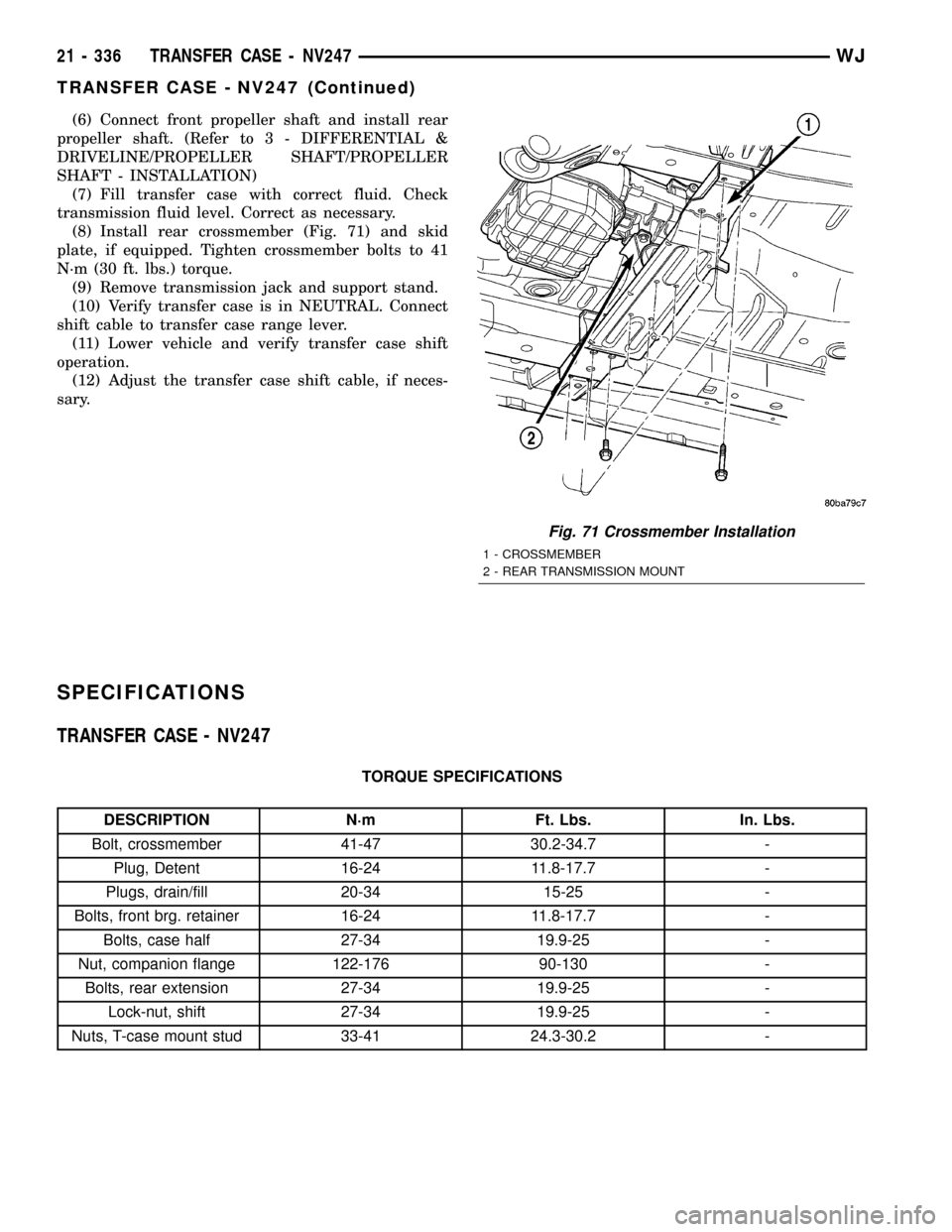
(8) Install rear crossmember (Fig. 71) and skid
plate, if equipped. Tighten crossmember bolts to 41
N´m (30 ft. lbs.) torque.
(9) Remove transmission jack and support stand.
(10) Verify transfer case is in NEUTRAL. Connect
shift cable to transfer case range lever.
(11) Lower vehicle and verify transfer case shift
operation.
(12) Adjust the transfer case shift cable, if neces-
sary.
SPECIFICATIONS
TRANSFER CASE - NV247
TORQUE SPECIFICATIONS
DESCRIPTION N´m Ft. Lbs. In. Lbs.
Bolt, crossmember 41-47 30.2-34.7 -
Plug, Detent 16-24 11.8-17.7 -
Plugs, drain/fill 20-34 15-25 -
Bolts, front brg. retainer 16-24 11.8-17.7 -
Bolts, case half 27-34 19.9-25 -
Nut, companion flange 122-176 90-130 -
Bolts, rear extension 27-34 19.9-25 -
Lock-nut, shift 27-34 19.9-25 -
Nuts, T-case mount stud 33-41 24.3-30.2 -
Fig. 71 Crossmember Installation
1 - CROSSMEMBER
2 - REAR TRANSMISSION MOUNT
21 - 336 TRANSFER CASE - NV247WJ
TRANSFER CASE - NV247 (Continued)
Page 1867 of 2199

DIAGNOSIS AND TESTING
DIAGNOSIS AND TESTING - PRESSURE
GAUGES
A quality air pressure gauge is recommended to
check tire pressure. After checking the air pressure,
replace valve cap finger tight.
DIAGNOSIS AND TESTING - TREAD WEAR
INDICATORS
Tread wear indicators are molded into the bottom
of the tread grooves. When tread depth is 1.6 mm
(1/16 in.), the tread wear indicators will appear as a
13 mm (1/2 in.) band (Fig. 15).
Tire replacement is necessary when indicators
appear in two or more grooves or if localized balding
occurs.
DIAGNOSIS AND TESTING - TIRE WEAR
PATTERNS
Under inflation will cause wear on the shoulders of
tire. Over inflation will cause wear at the center of
tire.
Excessive camber causes the tire to run at an
angle to the road. One side of tread is then worn
more than the other (Fig. 16).
Excessive toe-in or toe-out causes wear on the
tread edges and a feathered effect across the tread
(Fig. 16).
DIAGNOSIS AND TESTING - TIRE NOISE OR
VIBRATION
Radial-ply tires are sensitive to force impulses
caused by improper mounting, vibration, wheel
defects, or possibly tire imbalance.
To find out if tires are causing the noise or vibra-
tion, drive the vehicle over a smooth road at varying
speeds. Note the noise level during acceleration and
deceleration. The engine, differential and exhaust
noises will change as speed varies, while the tire
noise will usually remain constant.
STANDARD PROCEDURE - REPAIRING LEAKS
For proper repairing, a radial tire must be removed
from the wheel. Repairs should only be made if the
defect, or puncture, is in the tread area (Fig. 17). The
tire should be replaced if the puncture is located in
the sidewall.
Deflate tire completely before removing the tire
from the wheel. Use lubrication such as a mild soap
solution when dismounting or mounting tire. Use
tools free of burrs or sharp edges which could dam-
age the tire or wheel rim.
Before mounting tire on wheel, make sure all rust
is removed from the rim bead and repaint if neces-
sary.
Install wheel on vehicle, and tighten to proper
torque specification (Refer to 22 - TIRES/WHEELS/
WHEELS - SPECIFICATIONS).
Fig. 15 Tread Wear Indicators
1 - TREAD ACCEPTABLE
2 - TREAD UNACCEPTABLE
3 - WEAR INDICATOR
22 - 8 TIRES/WHEELSWJ
Page 2133 of 2199

(a) If the refrigerant system fails to reach the
specified vacuum, the system has a leak that must
be corrected. (Refer to 24 - HEATING & AIR CON-
DITIONING/PLUMBING - DIAGNOSIS AND
TESTING - REFRIGERANT SYSTEM LEAKS)
(b) If the refrigerant system maintains the spec-
ified vacuum for five minutes, restart the vacuum
pump, open the suction and discharge valves and
evacuate the system for an additional ten minutes.
(3) Close all of the valves, and turn off the charg-
ing station vacuum pump.
(4) The refrigerant system is now ready to be
charged with R-134a refrigerant. (Refer to 24 -
HEATING & AIR CONDITIONING/PLUMBING -
STANDARD PROCEDURE - REFRIGERANT SYS-
TEM CHARGE)
STANDARD PROCEDURE - REFRIGERANT
SYSTEM CHARGE
WARNING: REVIEW THE WARNINGS AND CAU-
TIONS IN THE FRONT OF THIS SECTION BEFORE
PERFORMING THE FOLLOWING OPERATION.
(Refer to 24 - HEATING & AIR CONDITIONING/
PLUMBING - WARNING) (Refer to 24 - HEATING &
AIR CONDITIONING/PLUMBING - CAUTION)
After the refrigerant system has been tested for
leaks and evacuated, a refrigerant charge can be
injected into the system. (Refer to 24 - HEATING &
AIR CONDITIONING/PLUMBING - SPECIFICA-
TIONS - CHARGE CAPACITY)
A R-134a refrigerant recovery/recycling/charging
station that meets SAE Standard J2210 must be
used to charge the refrigerant system with R-134a
refrigerant. Refer to the operating instructions sup-
plied by the equipment manufacturer for proper care
and use of this equipment.
PARTIAL CHARGE METHOD
WARNING: REVIEW THE WARNINGS AND CAU-
TIONS IN THE FRONT OF THIS SECTION BEFORE
PERFORMING THE FOLLOWING OPERATION.
(Refer to 24 - HEATING & AIR CONDITIONING/
PLUMBING - WARNING) (Refer to 24 - HEATING &
AIR CONDITIONING/PLUMBING - CAUTION)
The partial charge method is used to add a partial
charge to a refrigerant system that is low on refrig-
erant. To perform this procedure the evaporator inlet
and outlet tube temperatures are measured. The
temperature difference is measured with a tempera-
ture meter with one or two clamp-on thermocouple
probes. The difference between the evaporator inlet
and outlet tube temperatures will determine the
amount of refrigerant needed.Before adding a partial refrigerant charge, check
for refrigerant system leaks. (Refer to 24 - HEATING
& AIR CONDITIONING/PLUMBING - DIAGNOSIS
AND TESTING - REFRIGERANT SYSTEM LEAKS)
If a leak is found, make the necessary repairs before
attempting a full or partial refrigerant charge.
(1) Attach a manifold gauge set to the refrigerant
system service ports.
(2) Attach the two clamp-on thermocouple probes
to the inlet and outlet tubes of the evaporator coil.
²If a single thermocouple probe is used, attach
the probe to the evaporator inlet tube just before the
collar of the refrigerant line connector fitting. The
probe must make contact with the bottom surface of
the evaporator inlet tube.
²If dual thermocouple probes are used, attach
probe 1 to the evaporator inlet tube, and probe 2 to
the evaporator outlet tube. Attach both probes to the
evaporator tubes just before the collar of the refrig-
erant line connector fittings. The probes must make
contact with the bottom surfaces of the evaporator
inlet and outlet tubes.
(3) Open all of the windows or doors of the passen-
ger compartment.
(4) Set the A/C button on the A/C Heater controls
to the on position, the temperature control knob in
the full cool position, select Recirculation Mode, and
place the blower motor switch in the highest speed
position.
(5) Start the engine and hold the engine idle speed
at 1,000 rpm. Allow the engine to warm up to normal
operating temperature.
(6) The compressor clutch may cycle, depending
upon ambient temperature, humidity, and the refrig-
erant system charge level.
(7) Hold the engine idle speed at 1,000 rpm.
(8) Allow three to five minutes for the refrigerant
system to stabilize, then record the temperatures of
the evaporator inlet and outlet tubes.
²If a single probe is used, record the temperature
of the evaporator inlet tube. Then remove the probe
from the inlet tube and attach it to the evaporator
outlet tube just before the collar of the refrigerant
line connector fitting. The probe must make contact
with the bottom surface of the evaporator outlet tube.
Allow the thermocouple and meter time to stabilize,
then record the temperature of the evaporator outlet
tube. Subtract the inlet tube temperature reading
from the outlet tube temperature reading.
²If dual probes are used, record the temperatures
of both the evaporator inlet and outlet tubes. Then
subtract the inlet tube temperature reading from the
outlet tube temperature reading.
(9) If the measured temperature differential is
higher than 22É C to 26É C (40É F to 47É F), add 0.4
kilograms (14 ounces) of refrigerant.
24 - 56 PLUMBINGWJ
PLUMBING (Continued)
Page 2134 of 2199

(10) Allow three to five minutes for the refrigerant
system to stabilize, then take a second set of thermo-
couple measurements. Record the temperature differ-
ence to determine if an additional charge is required.(11) Record the compressor discharge pressure. If
the reading is higher than the pressure shown in the
Compressor Discharge Pressure Chart, the system
could be overcharged. If the reading is equal to, or
lower, than the pressure shown in the chart, continue
with this procedure.
Compressor Discharge Pressure Chart
Ambient
Temperature16ÉC
(60ÉF)21ÉC
(70ÉF)27ÉC
(80ÉF)32ÉC
(90ÉF)38ÉC
(100ÉF)43ÉC
(110ÉF)
Compressor
Discharge
Pressure1378 kPa
(200 psi)1516 kPa
(220 psi)1723 kPa
(250psi)1930 kPa
(280 psi)2206 kPa
(320 psi)2413 kPa
(350 psi)
(12)EXAMPLE:The ambient temperature is 21É
C (70É F). The evaporator inlet tube temperature is
12É C (54É F) and the evaporator outlet tube temper-
ature is 10É C (50É F). Subtract the inlet tube tem-
perature from the outlet tube temperature. The
difference is -2É C (-4É F). With a -2É C (-4É F) tem-
perature differential at 21É C (70É F) ambient tem-
perature, the system is fully charged.
(13) Add enough refrigerant to bring the refriger-
ant system up to a full charge.
(14) Remove the jumper wire from the low pres-
sure cycling clutch switch wire harness connector
and plug the connector back into the switch.
SPECIFICATIONS
CHARGE CAPACITY
The R-134a refrigerant system charge capacity for
this vehicle is 0.765 kilograms (1.687 pounds/27
ounces).
A/C COMPRESSOR
DESCRIPTION
DESCRIPTION - A/C COMPRESSOR
The air conditioning system uses a Nippondenso
10PA17 ten cylinder, double-acting swash plate-type
compressor on all models. This compressor has a
fixed displacement of 170 cubic centimeters (10.374
cubic inches), and has both the suction and discharge
ports located on the cylinder head. A label identifying
the use of R-134a refrigerant is located on the com-
pressor.
DESCRIPTION - HIGH PRESSURE RELIEF
VALVE
A high pressure relief valve is located on the com-
pressor manifold, which is on the side of the com-
pressor. This mechanical valve is designed to vent
refrigerant from the system to protect against dam-
age to the compressor and other system components,
caused by condenser air flow restriction or an over-
charge of refrigerant.
OPERATION
OPERATION - A/C COMPRESSOR
The compressor is driven by the engine through an
electric clutch, drive pulley and belt arrangement.
The compressor is lubricated by refrigerant oil that is
circulated throughout the refrigerant system with the
refrigerant.
The compressor draws in low-pressure refrigerant
vapor from the evaporator through its suction port. It
then compresses the refrigerant into a high-pressure,
high-temperature refrigerant vapor, which is then
pumped to the condenser through the compressor dis-
charge port.
The compressor cannot be repaired. If faulty or
damaged, the entire compressor assembly must be
replaced. The compressor clutch, pulley, and coil, are
available for service.
OPERATION - HIGH PRESSURE RELIEF VALVE
The high pressure relief valve vents the system
when a discharge pressure of 3445 to 4135 kPa (500
to 600 psi) or above is reached. The valve closes
when a minimum discharge pressure of 2756 kPa
(400 psi) is reached.
WJPLUMBING 24 - 57
PLUMBING (Continued)