2003 JEEP GRAND CHEROKEE differential
[x] Cancel search: differentialPage 165 of 2199

(3) Remove the pinion gear mate shaft lock screw
(Fig. 58).
(4) Remove pinion gear mate shaft with a drift and
hammer (Fig. 59).
(5) Install and lubricate Step Plate C-6960-3 (Fig.
60).
(6) Assemble Threaded Adapter C-6960-1 into top
side gear. Thread Forcing Screw C-6960-4 into
adapter until it becomes centered in adapter plate.
(7) Position a small screw driver in slot of
Threaded Adapter Disc C-6960-1 (Fig. 61) to prevent
adapter from turning.
Fig. 58 MATE SHAFT LOCK SCREW
1 - LOCK SCREW
2 - PINION GEAR MATE SHAFT
Fig. 59 PINION MATE SHAFT
1 - PINION MATE SHAFT
2 - SIDE GEAR
3 - DRIFT
4 - PINION MATE GEAR
Fig. 60 Step Plate
1 - LOWER SIDE GEAR
2 - DIFFERENTIAL CASE
3 - STEP PLATE
Fig. 61 Threaded Adapter Disc
1 - SOCKET
2 - SLOT IN ADAPTER
3 - SCREWDRIVER
4 - STEP PLATE
5 - FORCING SCREW
6 - THREAD ADAPTER DISC
3 - 120 REAR AXLE - 226RBAWJ
DIFFERENTIAL - TRAC-LOK (Continued)
Page 166 of 2199
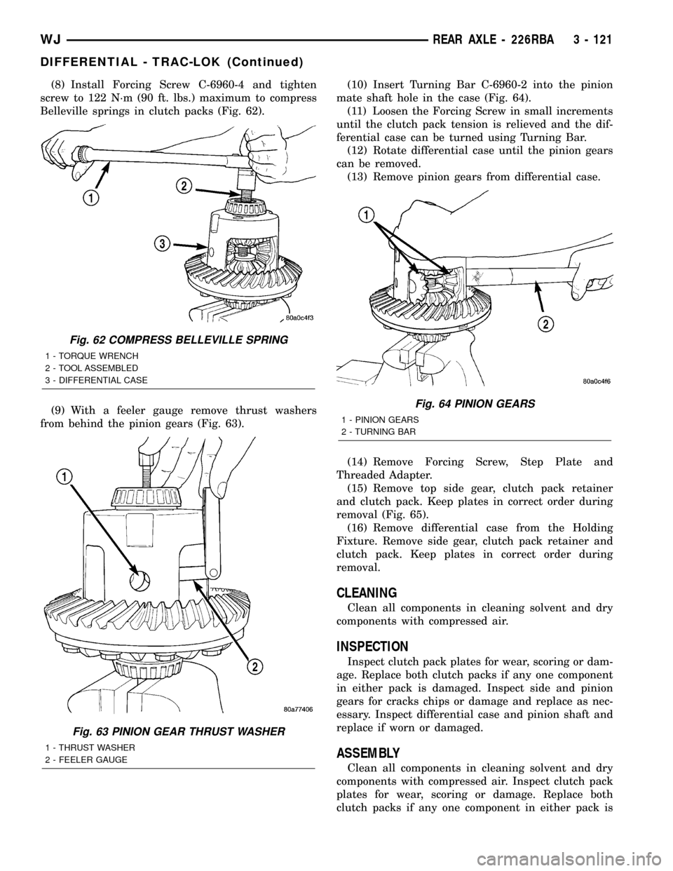
(8) Install Forcing Screw C-6960-4 and tighten
screw to 122 N´m (90 ft. lbs.) maximum to compress
Belleville springs in clutch packs (Fig. 62).
(9) With a feeler gauge remove thrust washers
from behind the pinion gears (Fig. 63).(10) Insert Turning Bar C-6960-2 into the pinion
mate shaft hole in the case (Fig. 64).
(11) Loosen the Forcing Screw in small increments
until the clutch pack tension is relieved and the dif-
ferential case can be turned using Turning Bar.
(12) Rotate differential case until the pinion gears
can be removed.
(13) Remove pinion gears from differential case.
(14) Remove Forcing Screw, Step Plate and
Threaded Adapter.
(15) Remove top side gear, clutch pack retainer
and clutch pack. Keep plates in correct order during
removal (Fig. 65).
(16) Remove differential case from the Holding
Fixture. Remove side gear, clutch pack retainer and
clutch pack. Keep plates in correct order during
removal.
CLEANING
Clean all components in cleaning solvent and dry
components with compressed air.
INSPECTION
Inspect clutch pack plates for wear, scoring or dam-
age. Replace both clutch packs if any one component
in either pack is damaged. Inspect side and pinion
gears for cracks chips or damage and replace as nec-
essary. Inspect differential case and pinion shaft and
replace if worn or damaged.
ASSEMBLY
Clean all components in cleaning solvent and dry
components with compressed air. Inspect clutch pack
plates for wear, scoring or damage. Replace both
clutch packs if any one component in either pack is
Fig. 62 COMPRESS BELLEVILLE SPRING
1 - TORQUE WRENCH
2 - TOOL ASSEMBLED
3 - DIFFERENTIAL CASE
Fig. 63 PINION GEAR THRUST WASHER
1 - THRUST WASHER
2 - FEELER GAUGE
Fig. 64 PINION GEARS
1 - PINION GEARS
2 - TURNING BAR
WJREAR AXLE - 226RBA 3 - 121
DIFFERENTIAL - TRAC-LOK (Continued)
Page 167 of 2199
damaged. Inspect side gears and pinions. Replace
any gear that is worn, cracked, chipped or damaged.
Inspect differential case and pinion shaft. Replace if
worn or damaged.
NOTE: New Plates and discs with fiber coating (no
grooves or lines) must be presoaked in Friction
Modifier before assembly. Soak plates and discs for
a minimum of 20 minutes.
(1) Lubricate each component with gear lubricant
before assembly.
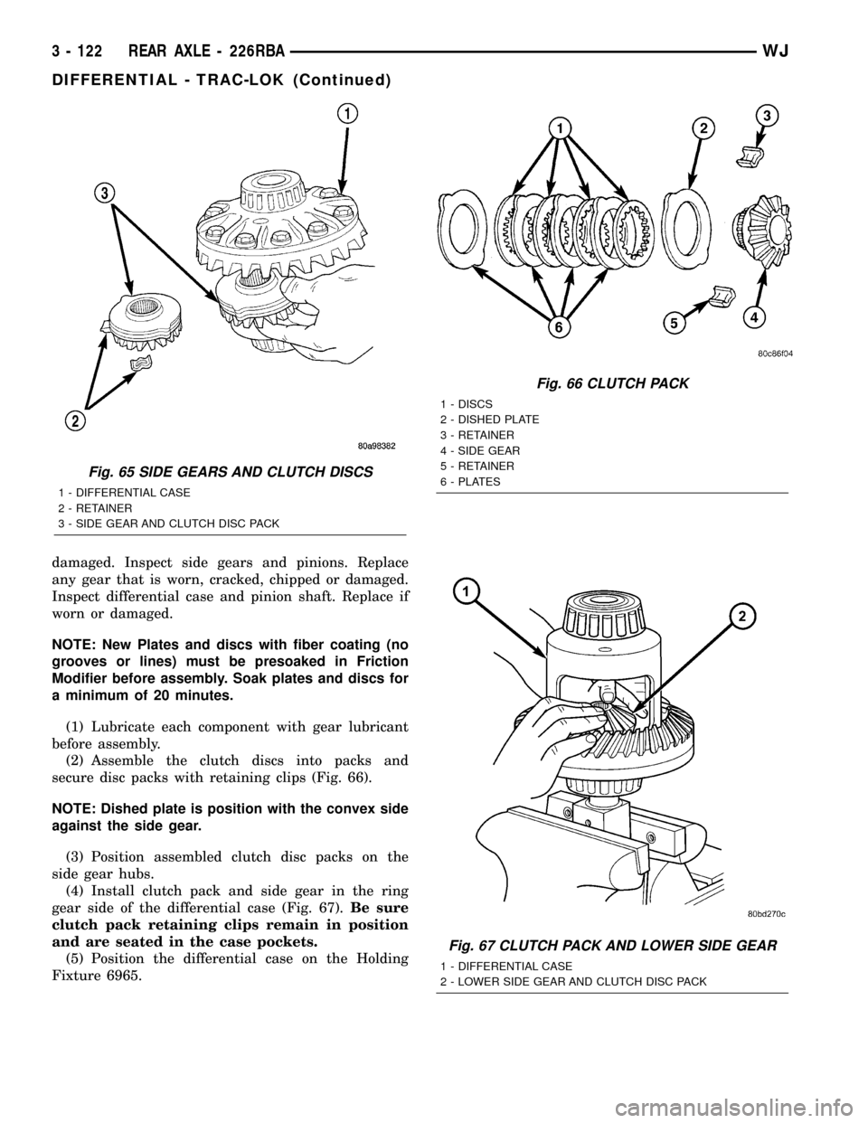
(2) Assemble the clutch discs into packs and
secure disc packs with retaining clips (Fig. 66).
NOTE: Dished plate is position with the convex side
against the side gear.
(3) Position assembled clutch disc packs on the
side gear hubs.
(4) Install clutch pack and side gear in the ring
gear side of the differential case (Fig. 67).Be sure
clutch pack retaining clips remain in position
and are seated in the case pockets.
(5) Position the differential case on the Holding
Fixture 6965.
Fig. 65 SIDE GEARS AND CLUTCH DISCS
1 - DIFFERENTIAL CASE
2 - RETAINER
3 - SIDE GEAR AND CLUTCH DISC PACK
Fig. 66 CLUTCH PACK
1 - DISCS
2 - DISHED PLATE
3 - RETAINER
4 - SIDE GEAR
5 - RETAINER
6 - PLATES
Fig. 67 CLUTCH PACK AND LOWER SIDE GEAR
1 - DIFFERENTIAL CASE
2 - LOWER SIDE GEAR AND CLUTCH DISC PACK
3 - 122 REAR AXLE - 226RBAWJ
DIFFERENTIAL - TRAC-LOK (Continued)
Page 168 of 2199
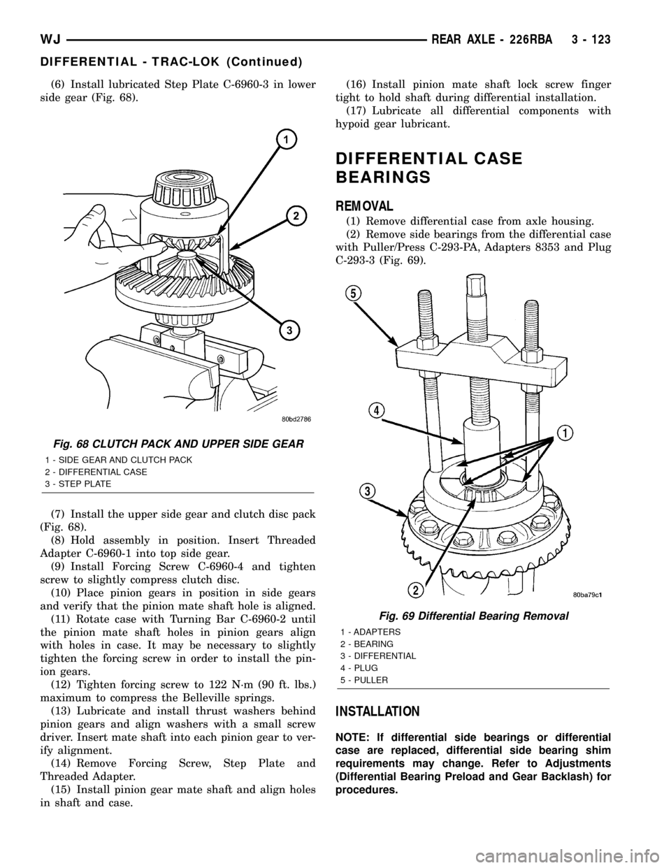
(6) Install lubricated Step Plate C-6960-3 in lower
side gear (Fig. 68).
(7) Install the upper side gear and clutch disc pack
(Fig. 68).
(8) Hold assembly in position. Insert Threaded
Adapter C-6960-1 into top side gear.
(9) Install Forcing Screw C-6960-4 and tighten
screw to slightly compress clutch disc.
(10) Place pinion gears in position in side gears
and verify that the pinion mate shaft hole is aligned.
(11) Rotate case with Turning Bar C-6960-2 until
the pinion mate shaft holes in pinion gears align
with holes in case. It may be necessary to slightly
tighten the forcing screw in order to install the pin-
ion gears.
(12) Tighten forcing screw to 122 N´m (90 ft. lbs.)
maximum to compress the Belleville springs.
(13) Lubricate and install thrust washers behind
pinion gears and align washers with a small screw
driver. Insert mate shaft into each pinion gear to ver-
ify alignment.
(14) Remove Forcing Screw, Step Plate and
Threaded Adapter.
(15) Install pinion gear mate shaft and align holes
in shaft and case.(16) Install pinion mate shaft lock screw finger
tight to hold shaft during differential installation.
(17) Lubricate all differential components with
hypoid gear lubricant.
DIFFERENTIAL CASE
BEARINGS
REMOVAL
(1) Remove differential case from axle housing.
(2) Remove side bearings from the differential case
with Puller/Press C-293-PA, Adapters 8353 and Plug
C-293-3 (Fig. 69).
INSTALLATION
NOTE: If differential side bearings or differential
case are replaced, differential side bearing shim
requirements may change. Refer to Adjustments
(Differential Bearing Preload and Gear Backlash) for
procedures.
Fig. 68 CLUTCH PACK AND UPPER SIDE GEAR
1 - SIDE GEAR AND CLUTCH PACK
2 - DIFFERENTIAL CASE
3 - STEP PLATE
Fig. 69 Differential Bearing Removal
1 - ADAPTERS
2 - BEARING
3 - DIFFERENTIAL
4 - PLUG
5 - PULLER
WJREAR AXLE - 226RBA 3 - 123
DIFFERENTIAL - TRAC-LOK (Continued)
Page 169 of 2199
CAUTION: Vari-lokTplenum must be seated against
the differential case prior to installing the ring gear
side differential bearing.
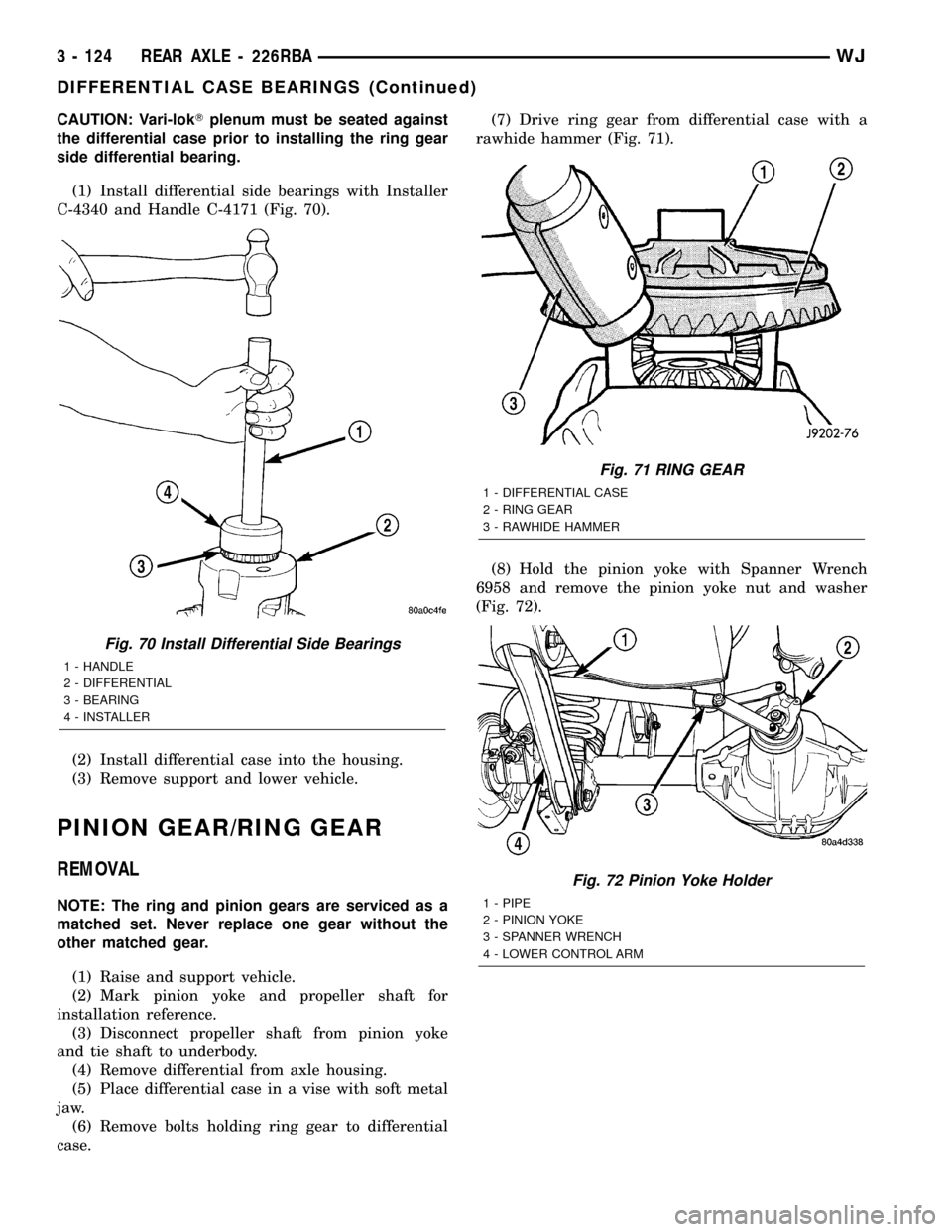
(1) Install differential side bearings with Installer
C-4340 and Handle C-4171 (Fig. 70).
(2) Install differential case into the housing.
(3) Remove support and lower vehicle.
PINION GEAR/RING GEAR
REMOVAL
NOTE: The ring and pinion gears are serviced as a
matched set. Never replace one gear without the
other matched gear.
(1) Raise and support vehicle.
(2) Mark pinion yoke and propeller shaft for
installation reference.
(3) Disconnect propeller shaft from pinion yoke
and tie shaft to underbody.
(4) Remove differential from axle housing.
(5) Place differential case in a vise with soft metal
jaw.
(6) Remove bolts holding ring gear to differential
case.(7) Drive ring gear from differential case with a
rawhide hammer (Fig. 71).
(8) Hold the pinion yoke with Spanner Wrench
6958 and remove the pinion yoke nut and washer
(Fig. 72).
Fig. 70 Install Differential Side Bearings
1 - HANDLE
2 - DIFFERENTIAL
3 - BEARING
4 - INSTALLER
Fig. 71 RING GEAR
1 - DIFFERENTIAL CASE
2 - RING GEAR
3 - RAWHIDE HAMMER
Fig. 72 Pinion Yoke Holder
1 - PIPE
2 - PINION YOKE
3 - SPANNER WRENCH
4 - LOWER CONTROL ARM
3 - 124 REAR AXLE - 226RBAWJ
DIFFERENTIAL CASE BEARINGS (Continued)
Page 173 of 2199
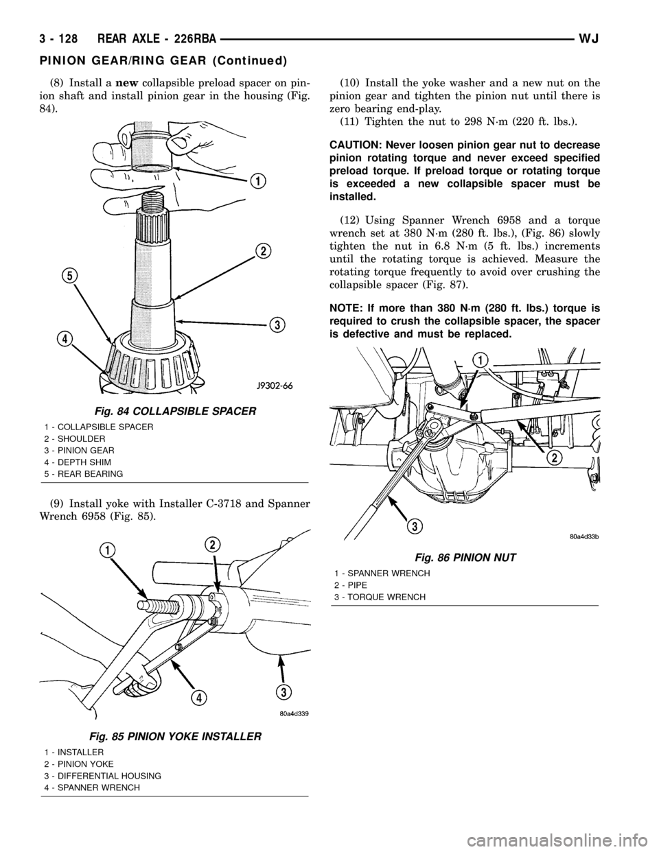
(8) Install anewcollapsible preload spacer on pin-
ion shaft and install pinion gear in the housing (Fig.
84).
(9) Install yoke with Installer C-3718 and Spanner
Wrench 6958 (Fig. 85).(10) Install the yoke washer and a new nut on the
pinion gear and tighten the pinion nut until there is
zero bearing end-play.
(11) Tighten the nut to 298 N´m (220 ft. lbs.).
CAUTION: Never loosen pinion gear nut to decrease
pinion rotating torque and never exceed specified
preload torque. If preload torque or rotating torque
is exceeded a new collapsible spacer must be
installed.
(12) Using Spanner Wrench 6958 and a torque
wrench set at 380 N´m (280 ft. lbs.), (Fig. 86) slowly
tighten the nut in 6.8 N´m (5 ft. lbs.) increments
until the rotating torque is achieved. Measure the
rotating torque frequently to avoid over crushing the
collapsible spacer (Fig. 87).
NOTE: If more than 380 N´m (280 ft. lbs.) torque is
required to crush the collapsible spacer, the spacer
is defective and must be replaced.
Fig. 84 COLLAPSIBLE SPACER
1 - COLLAPSIBLE SPACER
2 - SHOULDER
3 - PINION GEAR
4 - DEPTH SHIM
5 - REAR BEARING
Fig. 85 PINION YOKE INSTALLER
1 - INSTALLER
2 - PINION YOKE
3 - DIFFERENTIAL HOUSING
4 - SPANNER WRENCH
Fig. 86 PINION NUT
1 - SPANNER WRENCH
2 - PIPE
3 - TORQUE WRENCH
3 - 128 REAR AXLE - 226RBAWJ
PINION GEAR/RING GEAR (Continued)
Page 174 of 2199
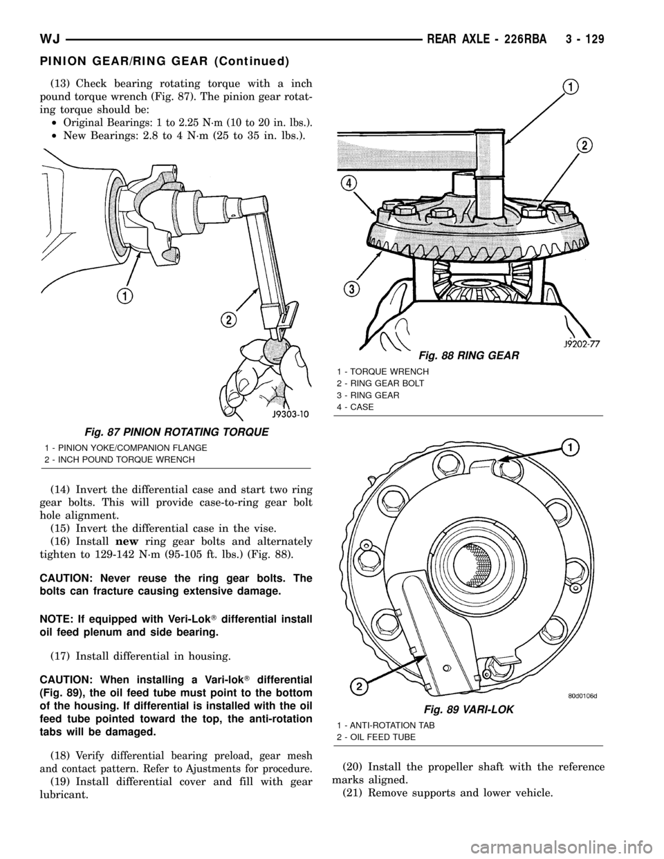
(13) Check bearing rotating torque with a inch
pound torque wrench (Fig. 87). The pinion gear rotat-
ing torque should be:
²
Original Bearings: 1 to 2.25 N´m (10 to 20 in. lbs.).
²New Bearings: 2.8 to 4 N´m (25 to 35 in. lbs.).
(14) Invert the differential case and start two ring
gear bolts. This will provide case-to-ring gear bolt
hole alignment.
(15) Invert the differential case in the vise.
(16) Installnewring gear bolts and alternately
tighten to 129-142 N´m (95-105 ft. lbs.) (Fig. 88).
CAUTION: Never reuse the ring gear bolts. The
bolts can fracture causing extensive damage.
NOTE: If equipped with Veri-LokTdifferential install
oil feed plenum and side bearing.
(17) Install differential in housing.
CAUTION: When installing a Vari-lokTdifferential
(Fig. 89), the oil feed tube must point to the bottom
of the housing. If differential is installed with the oil
feed tube pointed toward the top, the anti-rotation
tabs will be damaged.
(18)
Verify differential bearing preload, gear mesh
and contact pattern. Refer to Ajustments for procedure.
(19) Install differential cover and fill with gear
lubricant.(20) Install the propeller shaft with the reference
marks aligned.
(21) Remove supports and lower vehicle.
Fig. 87 PINION ROTATING TORQUE
1 - PINION YOKE/COMPANION FLANGE
2 - INCH POUND TORQUE WRENCH
Fig. 88 RING GEAR
1 - TORQUE WRENCH
2 - RING GEAR BOLT
3 - RING GEAR
4 - CASE
Fig. 89 VARI-LOK
1 - ANTI-ROTATION TAB
2 - OIL FEED TUBE
WJREAR AXLE - 226RBA 3 - 129
PINION GEAR/RING GEAR (Continued)
Page 204 of 2199
(5) Install the cluster bezel (Refer to 23 - BODY/
INSTRUMENT PANEL/CLUSTER BEZEL -
INSTALLATION).
(6) Reconnect the negative battery cable.
POWER BRAKE BOOSTER
DESCRIPTION
The booster assembly consists of a housing divided
into separate chambers by two internal diaphragms.
The outer edge of each diaphragm is attached to the
booster housing.
Two push rods are used in the booster. The pri-
mary push rod connects the booster to the brake
pedal. The secondary push rod connects the booster
to the master cylinder to stroke the cylinder pistons.
OPERATION
The atmospheric inlet valve is opened and closed
by the primary push rod. Booster vacuum supply is
through a hose attached to an intake manifold fittingat one end and to the booster check valve at the
other. The vacuum check valve in the booster housing
is a one-way device that prevents vacuum leak back.
Power assist is generated by utilizing the pressure
differential between normal atmospheric pressure
and a vacuum. The vacuum needed for booster oper-
ation is taken directly from the engine intake mani-
fold. The entry point for atmospheric pressure is
through a filter and inlet valve at the rear of the
housing (Fig. 59) .
The chamber areas forward of the booster dia-
phragms are exposed to vacuum from the intake
manifold. The chamber areas to the rear of the dia-
phragms, are exposed to normal atmospheric pres-
sure of 101.3 kilopascals (14.7 pounds/square in.).
Brake pedal application causes the primary push
rod to open the atmospheric inlet valve. This exposes
the area behind the diaphragms to atmospheric pres-
sure. The resulting pressure differential provides the
extra apply force for power assist.
The booster check valve, check valve grommet and
booster seals are serviceable.
WJBRAKES - BASE 5 - 29
PEDAL MOTOR (Continued)