2003 JEEP GRAND CHEROKEE Connectors
[x] Cancel search: ConnectorsPage 1473 of 2199

INSTALLATION - 4.7L
(1) Clean throttle body-to-intake manifold o-ring.
(2) Clean mating surfaces of throttle body and
intake manifold.
(3) Install throttle body to intake manifold by posi-
tioning throttle body to manifold alignment pins.
(4) Install three mounting bolts. Tighten bolts to
12 N´m (105 in. lbs.) torque.
(5) Install control cables.
(6) Install vacuum line to throttle body.
(7) Install electrical connectors.
(8) Install air duct/air box at throttle body.
THROTTLE CONTROL CABLE
REMOVAL
REMOVAL - 4.0L
CAUTION: Be careful not to damage or kink the
cable core wire (within the cable sheathing) while
servicing accelerator pedal or throttle cable.
(1) From inside vehicle, hold up accelerator pedal.
Remove plastic cable retainer (clip) and throttle cable
core wire from upper end of pedal arm (Fig. 16).
Plastic cable retainer (clip) snaps into pedal arm.
(2) Remove cable core wire at pedal arm.
(3) From inside vehicle, remove clip holding cable
to dashpanel (Fig. 16).
(4) Remove cable housing from dash panel and
pull into engine compartment.
(5) Remove (unsnap) cable from routing clips on
engine valve cover.
(6) Remove cable connector at throttle body
bellcrank ball by unsnapping rearward (Fig. 37).
(7) Remove throttle cable from bracket by com-
pressing release tabs (Fig. 37) and pushing cable
through hole in bracket.
(8) Remove throttle cable from vehicle.
Fig. 35 Throttle Body and Sensor LocationsÐ4.0L
Engine
1 - MOUNTING BOLTS (4)
2 - THROTTLE BODY
3 - IAC MOTOR
4 - ELEC. CONN.
5 - TPS
6 - MAP SENSOR
7 - ELEC. CONN.
8 - IAT SENSOR
9 - ELEC. CONN.
Fig. 36 Throttle Body, Sensors and Electrical
ConnectorsÐ4.7L V-8 Engine
1 - MOUNTING BOLTS (3)
2 - THROTTLE BODY
3 - IAT SENSOR CONNECTOR
4 - IAC MOTOR CONNECTOR
5 - TPS CONNECTOR
14 - 54 FUEL INJECTIONWJ
THROTTLE BODY (Continued)
Page 1490 of 2199

necessary, the steering column assembly must be
replaced,(Refer to 19 - STEERING/COLUMN -
REMOVAL).
REMOVAL
IGNITION SWITCH REMOVAL
The ignition key must be in the key cylinder for
cylinder removal. The key cylinder must be removed
first before removing ignition switch.
(1) Remove key cylinder. Refer to previous steps.
(2) Remove lower steering column cover screws
and remove cover (Fig. 19).
(3) Remove ignition switch mounting screw (Fig.
17). Use tamper proof torx bit to remove the screw.
(4) Using a small screwdriver, push on locking tab
(Fig. 15) and remove switch from steering column.
(5) Disconnect two electrical connectors at rear of
ignition switch (Fig. 17).
INSTALLATION
IGNITION SWITCH INSTALLATION
The ignition key must be in the key cylinder for
cylinder removal. The key cylinder must be removed
first before removing ignition switch.(1) Before installing ignition switch, rotate the slot
in the switch to the ON position (Fig. 16).
(2) Connect two electrical connectors to rear of
ignition switch. Make sure that locking tabs are fully
seated into wiring connectors.
(3) Position switch to column and install tamper
proof screw. Tighten screw to 3 N´m (26 in. lbs.).
(4) Install steering column lower cover.
Fig. 15 Ignition Switch Lock Tab
1 - LOCK TAB
2 - IGNITION SWITCH
3 - SCREWDRIVER
Fig. 16 Switch In ON Position
1 - IGNITION SWITCH
2 - ROTATE TO ON POSITION
Fig. 17 Ignition Switch Removal/Installation
1 - TAMPER PROOF SCREW
2 - IGNITION SWITCH
3 - ELECTRICAL CONNECTORS
WJCOLUMN 19 - 13
IGNITION SWITCH (Continued)
Page 1541 of 2199

CONDITION POSSIBLE CAUSES CORRECTION
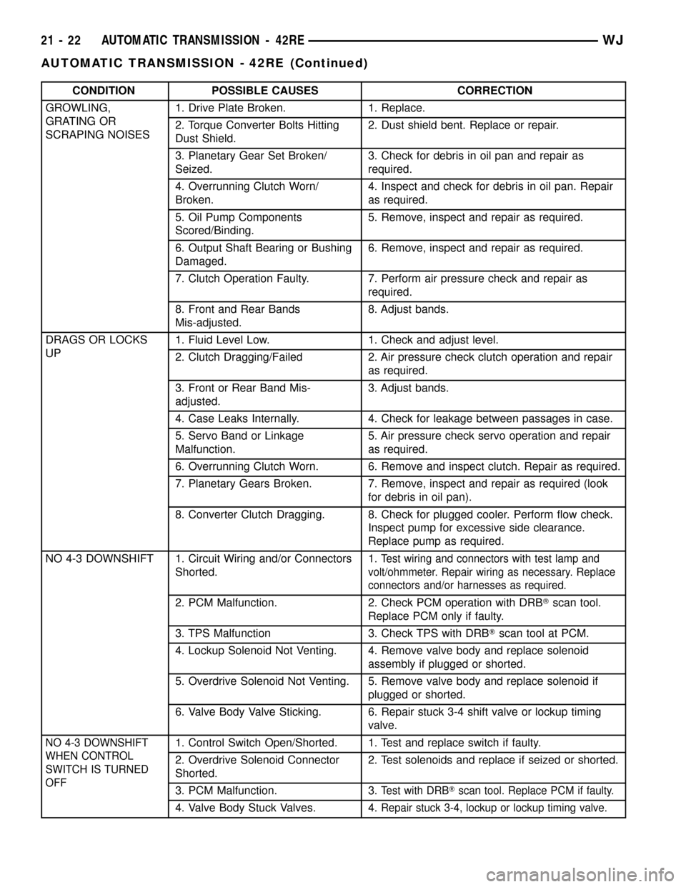
GROWLING,
GRATING OR
SCRAPING NOISES1. Drive Plate Broken. 1. Replace.
2. Torque Converter Bolts Hitting
Dust Shield.2. Dust shield bent. Replace or repair.
3. Planetary Gear Set Broken/
Seized.3. Check for debris in oil pan and repair as
required.
4. Overrunning Clutch Worn/
Broken.4. Inspect and check for debris in oil pan. Repair
as required.
5. Oil Pump Components
Scored/Binding.5. Remove, inspect and repair as required.
6. Output Shaft Bearing or Bushing
Damaged.6. Remove, inspect and repair as required.
7. Clutch Operation Faulty. 7. Perform air pressure check and repair as
required.
8. Front and Rear Bands
Mis-adjusted.8. Adjust bands.
DRAGS OR LOCKS
UP1. Fluid Level Low. 1. Check and adjust level.
2. Clutch Dragging/Failed 2. Air pressure check clutch operation and repair
as required.
3. Front or Rear Band Mis-
adjusted.3. Adjust bands.
4. Case Leaks Internally. 4. Check for leakage between passages in case.
5. Servo Band or Linkage
Malfunction.5. Air pressure check servo operation and repair
as required.
6. Overrunning Clutch Worn. 6. Remove and inspect clutch. Repair as required.
7. Planetary Gears Broken. 7. Remove, inspect and repair as required (look
for debris in oil pan).
8. Converter Clutch Dragging. 8. Check for plugged cooler. Perform flow check.
Inspect pump for excessive side clearance.
Replace pump as required.
NO 4-3 DOWNSHIFT 1. Circuit Wiring and/or Connectors
Shorted.1.
Test wiring and connectors with test lamp and
volt/ohmmeter. Repair wiring as necessary. Replace
connectors and/or harnesses as required.
2. PCM Malfunction. 2. Check PCM operation with DRBTscan tool.
Replace PCM only if faulty.
3. TPS Malfunction 3. Check TPS with DRBTscan tool at PCM.
4. Lockup Solenoid Not Venting. 4. Remove valve body and replace solenoid
assembly if plugged or shorted.
5. Overdrive Solenoid Not Venting. 5. Remove valve body and replace solenoid if
plugged or shorted.
6. Valve Body Valve Sticking. 6. Repair stuck 3-4 shift valve or lockup timing
valve.
NO 4-3 DOWNSHIFT
WHEN CONTROL
SWITCH IS TURNED
OFF1. Control Switch Open/Shorted. 1. Test and replace switch if faulty.
2. Overdrive Solenoid Connector
Shorted.2. Test solenoids and replace if seized or shorted.
3. PCM Malfunction. 3.
Test with DRBTscan tool. Replace PCM if faulty.
4. Valve Body Stuck Valves. 4.Repair stuck 3-4, lockup or lockup timing valve.
21 - 22 AUTOMATIC TRANSMISSION - 42REWJ
AUTOMATIC TRANSMISSION - 42RE (Continued)
Page 1543 of 2199

CONDITION POSSIBLE CAUSES CORRECTION
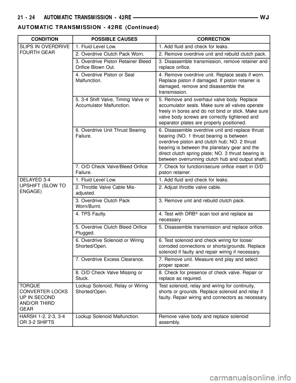
SLIPS IN OVERDRIVE
FOURTH GEAR1. Fluid Level Low. 1. Add fluid and check for leaks.
2. Overdrive Clutch Pack Worn. 2. Remove overdrive unit and rebuild clutch pack.
3. Overdrive Piston Retainer Bleed
Orifice Blown Out.3. Disassemble transmission, remove retainer and
replace orifice.
4. Overdrive Piston or Seal
Malfunction.4. Remove overdrive unit. Replace seals if worn.
Replace piston if damaged. If piston retainer is
damaged, remove and disassemble the
transmission.
5. 3-4 Shift Valve, Timing Valve or
Accumulator Malfunction.5. Remove and overhaul valve body. Replace
accumulator seals. Make sure all valves operate
freely in bores and do not bind or stick. Make sure
valve body screws are correctly tightened and
separator plates are properly positioned.
6. Overdrive Unit Thrust Bearing
Failure.6. Disassemble overdrive unit and replace thrust
bearing (NO. 1 thrust bearing is between
overdrive piston and clutch hub; NO. 2 thrust
bearing is between the planetary gear and the
direct clutch spring plate; NO. 3 thrust bearing is
between overrunning clutch hub and output shaft).
7. O/D Check Valve/Bleed Orifice
Failure.7. Check for function/secure orifice insert in O/D
piston retainer.
DELAYED 3-4
UPSHIFT (SLOW TO
ENGAGE)1. Fluid Level Low. 1. Add fluid and check for leaks.
2. Throttle Valve Cable Mis-
adjusted.2. Adjust throttle valve cable.
3. Overdrive Clutch Pack
Worn/Burnt.3. Remove unit and rebuild clutch pack.
4. TPS Faulty. 4. Test with DRBTscan tool and replace as
necessary
5. Overdrive Clutch Bleed Orifice
Plugged.5. Disassemble transmission and replace orifice.
6. Overdrive Solenoid or Wiring
Shorted/Open.6. Test solenoid and check wiring for loose/
corroded connections or shorts/grounds. Replace
solenoid if faulty and repair wiring if necessary.
7. Overdrive Excess Clearance. 7. Remove unit. Measure end play and select
proper spacer.
8. O/D Check Valve Missing or
Stuck.8. Check for presence of check valve. Repair or
replace as required.
TORQUE
CONVERTER LOCKS
UP IN SECOND
AND/OR THIRD
GEARLockup Solenoid, Relay or Wiring
Shorted/Open.Test solenoid, relay and wiring for continuity,
shorts or grounds. Replace solenoid and relay if
faulty. Repair wiring and connectors as necessary.
HARSH 1-2, 2-3, 3-4
OR 3-2 SHIFTSLockup Solenoid Malfunction. Remove valve body and replace solenoid
assembly.
21 - 24 AUTOMATIC TRANSMISSION - 42REWJ
AUTOMATIC TRANSMISSION - 42RE (Continued)
Page 1544 of 2199

CONDITION POSSIBLE CAUSES CORRECTION
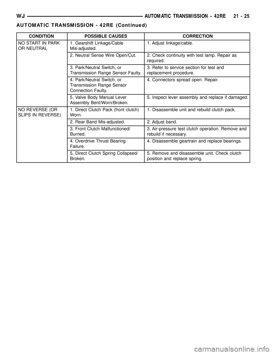
NO START IN PARK
OR NEUTRAL1. Gearshift Linkage/Cable
Mis-adjusted.1. Adjust linkage/cable.
2. Neutral Sense Wire Open/Cut. 2. Check continuity with test lamp. Repair as
required.
3. Park/Neutral Switch, or
Transmission Range Sensor Faulty.3. Refer to service section for test and
replacement procedure.
4. Park/Neutral Switch, or
Transmission Range Sensor
Connection Faulty.4. Connectors spread open. Repair.
5. Valve Body Manual Lever
Assembly Bent/Worn/Broken.5. Inspect lever assembly and replace if damaged.
NO REVERSE (OR
SLIPS IN REVERSE)1. Direct Clutch Pack (front clutch)
Worn.1. Disassemble unit and rebuild clutch pack.
2. Rear Band Mis-adjusted. 2. Adjust band.
3. Front Clutch Malfunctioned/
Burned.3. Air-pressure test clutch operation. Remove and
rebuild if necessary.
4. Overdrive Thrust Bearing
Failure.4. Disassemble geartrain and replace bearings.
5. Direct Clutch Spring Collapsed/
Broken.5. Remove and disassemble unit. Check clutch
position and replace spring.
WJAUTOMATIC TRANSMISSION - 42RE 21 - 25
AUTOMATIC TRANSMISSION - 42RE (Continued)
Page 1586 of 2199

REMOVAL
(1) Hoist and support vehicle on safety stands.
(2) Remove transmission fluid pan and filter.
(3) Disengage wire connectors from pressure sen-
sor and solenoid (Fig. 75).
(4) Remove screws holding pressure solenoid
retainer to governor body.
(5) Separate solenoid retainer from governor (Fig.
76).
(6) Pull solenoid from governor body (Fig. 77).
(7) Pull pressure sensor from governor body.
(8) Remove bolts holding governor body to valve
body.(9) Separate governor body from valve body (Fig.
78).
(10) Remove governor body gasket.
INSTALLATION
Before installing the pressure sensor and solenoid
in the governor body, replace o-ring seals, clean the
gasket surfaces and replace gasket.
(1) Place gasket in position on back of governor
body (Fig. 79).
(2) Place governor body in position on valve body.
(3) Install bolts to hold governor body to valve
body.
(4) Lubricate o-ring on pressure sensor with trans-
mission fluid.
(5) Align pressure sensor to bore in governor body.
Fig. 75 Governor Solenoid And Pressure Sensor
1 - PRESSURE SENSOR
2 - PRESSURE SOLENOID
3 - GOVERNOR
Fig. 76 Pressure Solenoid Retainer
1 - PRESSURE SOLENOID RETAINER
2 - GOVERNOR
Fig. 77 Pressure Solenoid and O-ring
1 - PRESSURE SOLENOID
2 - O-RING
3 - GOVERNOR
Fig. 78 Governor Body and Gasket
1 - GOVERNOR BODY
2 - GASKET
WJAUTOMATIC TRANSMISSION - 42RE 21 - 67
ELECTRONIC GOVERNOR (Continued)
Page 1587 of 2199

(6) Push pressure sensor into governor body.
(7) Lubricate o-ring, on pressure solenoid, with
transmission fluid.
(8) Align pressure solenoid to bore in governor
body (Fig. 80).
(9) Push solenoid into governor body.
(10) Place solenoid retainer in position on governor
(Fig. 81).
(11) Install screws to hold pressure solenoid
retainer to governor body.
(12) Engage wire connectors into pressure sensor
and solenoid (Fig. 82).
(13) Install transmission fluid pan and (new) filter.
(14) Lower vehicle and road test to verify repair.
EXTENSION HOUSING
BUSHING
REMOVAL
(1) Remove extension housing yoke seal.
(2) Insert Remover 6957 into the extension hous-
ing. Tighten tool to bushing and remove bushing
(Fig. 83).
INSTALLATION
(1) Align bushing oil hole with oil slot in extension
housing.
(2) Tap bushing into place with Installer 6951 and
Handle C-4171.
Fig. 79 Governor Body and Gasket
1 - GOVERNOR BODY
2 - GASKET
Fig. 80 Pressure Solenoid and O-ring
1 - PRESSURE SOLENOID
2 - O-RING
3 - GOVERNOR
Fig. 81 Pressure Solenoid Retainer
1 - PRESSURE SOLENOID RETAINER
2 - GOVERNOR
Fig. 82 Governor Solenoid And Pressure Sensor
1 - PRESSURE SENSOR
2 - PRESSURE SOLENOID
3 - GOVERNOR
21 - 68 AUTOMATIC TRANSMISSION - 42REWJ
ELECTRONIC GOVERNOR (Continued)
Page 1599 of 2199

INCORRECT if the engine starts in one but not both
positions. If the engine starts in any position other
than PARK or NEUTRAL, or if the engine will not
start at all, the park/neutral position switch or TRS
may be faulty.
(1) Shift transmission into PARK.
(2) Remove floor console as necessary for access to
the shift cable adjustment. (Refer to 23 - BODY/IN-
TERIOR/FLOOR CONSOLE - REMOVAL)
(3) Loosen the shift cable adjustment screw (Fig.
106).
(4) Raise vehicle.
(5) Unsnap cable eyelet from transmission shift
lever (Fig. 107).
(6) Verify transmission shift lever is in PARK
detent by moving lever fully rearward. Last rearward
detent is PARK position.
(7) Verify positive engagement of transmission
park lock by attempting to rotate propeller shaft.
Shaft will not rotate when park lock is engaged.
(8) Snap cable eyelet onto transmission shift lever.
(9) Lower vehicle
(10) Tighten the shift cable adjustment screw to 7
N´m (65 in.lbs.).
(11) Verify correct operation.
(12) Install any floor console components removed
for access. (Refer to 23 - BODY/INTERIOR/FLOOR
CONSOLE - INSTALLATION)
OIL PUMP
DESCRIPTION
The oil pump (Fig. 108) is located in the pump
housing inside the bell housing of the transmission
case. The oil pump consists of an inner and outer
gear (Fig. 109), a housing, and a cover that also
serves as the reaction shaft support.
OPERATION
As the torque converter rotates, the converter hub
rotates the inner and outer gears. As the gears
rotate, the clearance between the gear teeth
increases in the crescent area, and creates a suction
at the inlet side of the pump. This suction draws
fluid through the pump inlet from the oil pan. As the
clearance between the gear teeth in the crescent area
decreases, it forces pressurized fluid into the pump
outlet and to the valve body.
Fig. 106 Shift Cable at the Shifter
1 - SHIFT LEVER PIN
2 - ADJUSTMENT SCREW
3 - SHIFT CABLE
4 - SHIFTER ASSEMBLY BRACKET
Fig. 107 Shift Cable at Transmission
1 - TRANSMISSION SHIFTER CABLE
2 - THROTTLE VALVE CABLE
3 - TRANSFER CASE SHIFTER CABLE
4 - TRANSFER CASE SHIFTER CABLE BRACKET RETAINING
BOLT(S)
5 - THROTTLE VALVE CABLE BRACKET RETAINING BOLT
6 - ELECTRICAL CONNECTORS
7 - TRANSMISSION FLUID LINES
21 - 80 AUTOMATIC TRANSMISSION - 42REWJ
GEARSHIFT CABLE (Continued)