2003 JEEP GRAND CHEROKEE drive belt
[x] Cancel search: drive beltPage 1382 of 2199
EXHAUST MANIFOLD - RIGHT
DESCRIPTION
The exhaust manifolds are log style with a pat-
ented flow enhancing design to maximize perfor-
mance. The exhaust manifolds are made of high
silicon molybdenum cast iron. A perforated core
graphite exhaust manifold gasket is used to improve
sealing to the cylinder head. The exhaust manifolds
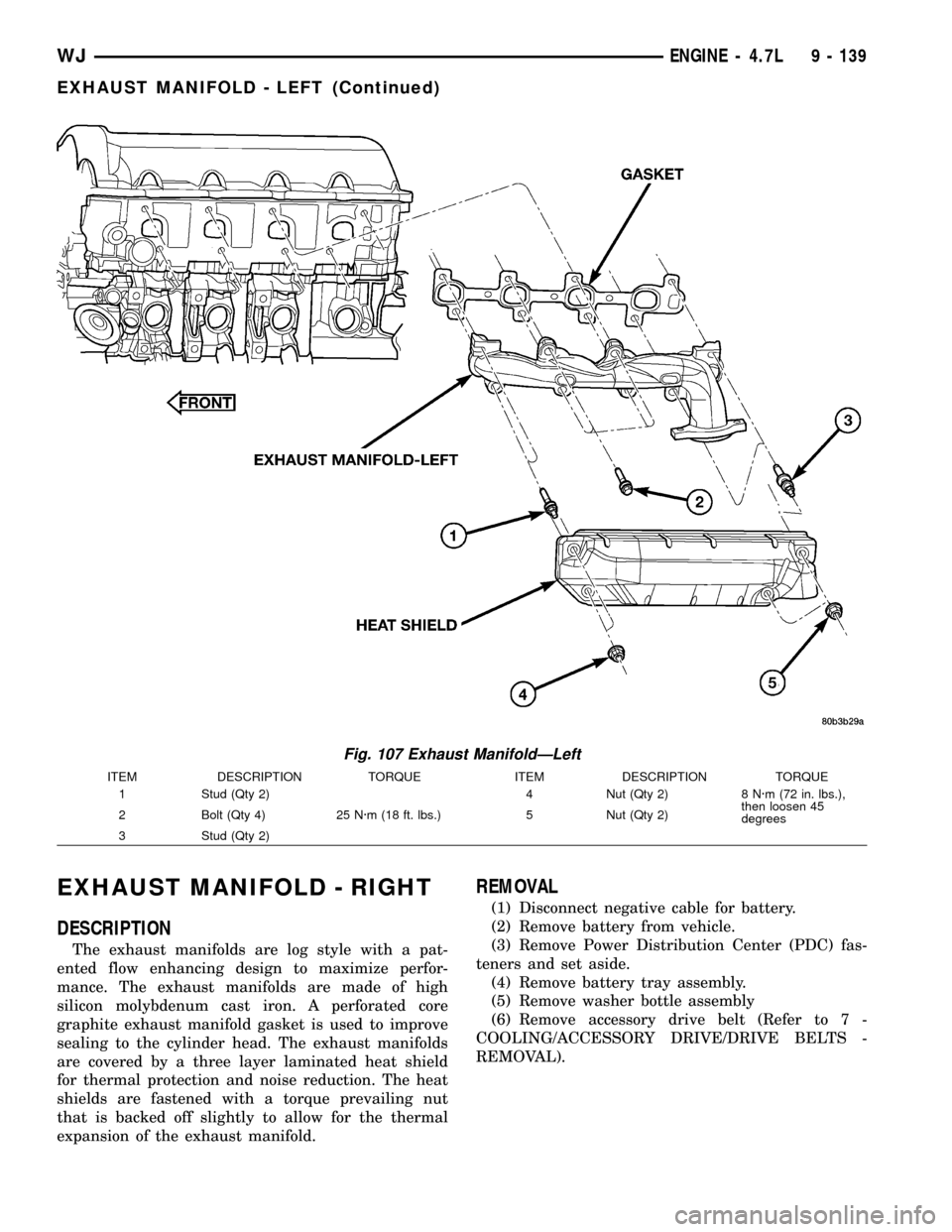
are covered by a three layer laminated heat shield
for thermal protection and noise reduction. The heat
shields are fastened with a torque prevailing nut
that is backed off slightly to allow for the thermal
expansion of the exhaust manifold.
REMOVAL
(1) Disconnect negative cable for battery.
(2) Remove battery from vehicle.
(3) Remove Power Distribution Center (PDC) fas-
teners and set aside.
(4) Remove battery tray assembly.
(5) Remove washer bottle assembly
(6) Remove accessory drive belt (Refer to 7 -
COOLING/ACCESSORY DRIVE/DRIVE BELTS -
REMOVAL).
Fig. 107 Exhaust ManifoldÐLeft
ITEM DESCRIPTION TORQUE ITEM DESCRIPTION TORQUE
1 Stud (Qty 2)
25 N´m (18 ft. lbs.)4 Nut (Qty 2) 8 N´m (72 in. lbs.),
then loosen 45
degrees 2 Bolt (Qty 4) 5 Nut (Qty 2)
3 Stud (Qty 2)
WJENGINE - 4.7L 9 - 139
EXHAUST MANIFOLD - LEFT (Continued)
Page 1384 of 2199

INSPECTION
(1) Inspect the exhaust manifold for cracks in the
mating surface and at every mounting bolt hole.
(2) Using a straight edge and a feeler gauge, check
the mating surface for warp and twist.
(3) Inspect the manifold to exhaust pipe mating
surface for cracks, gouges, or other damage that
would prevent sealing.
INSTALLATION
(1) Install exhaust manifold and gasket from below
engine compartment.
(2) Install lower exhaust manifold fasteners. DO
NOT tighten until all fasteners are in place.
(3) Lower vehicle and install upper exhaust mani-
fold fasteners. Tighten all manifold bolts starting at
center and working outward to 25 N´m (18 ft. lbs.).
CAUTION: Over tightening heat shield fasteners,
may cause shield to distort and/or crack.
(4) Install exhaust manifold heat shield. Tighten
fasteners to 8 N´m (72 in. lbs.), then loosen 45
degrees.
(5) Install starter and fasteners.
(6) Connect exhaust pipe to manifold.
(7) Connect heater hoses at engine.
(8) Install fastener attaching A/C accumulator.
(9) Install A/C compressor and fasteners.
(10) Install accessory drive belt (Refer to 7 -
COOLING/ACCESSORY DRIVE/DRIVE BELTS -
INSTALLATION).
(11) Install washer bottle and battery tray assem-
bly.
(12) Install PDC.
(13) Install battery and connect cables.
(14) Fill cooling system (Refer to 7 - COOLING -
STANDARD PROCEDURE).
VALVE TIMING
DESCRIPTION - TIMING DRIVE SYSTEM
The timing drive system has been designed to pro-
vide quiet performance and reliability to support a
non-free wheelingengine. Specifically the intake
valves are non-free wheeling and can be easily dam-
aged with forceful engine rotation if camshaft-to-
crankshaft timing is incorrect. The timing drive
system consists of a primary chain and two second-
ary timing chain drives (Fig. 109).
OPERATION - TIMING DRIVE SYSTEM
The primary timing chain is a single inverted tooth
type. The primary chain drives the large fifty tooth
idler sprocket directly from a 25 tooth crankshaftsprocket. Primary chain motion is controlled by a
pivoting leaf spring tensioner arm and a fixed guide.
The arm and the guide both use nylon plastic wear
faces for low friction and long wear. The primary
chain receives oil splash lubrication from the second-
ary chain drive and oil pump leakage. The idler
sprocket assembly connects the primary and second-
ary chain drives. The idler sprocket assembly con-
sists of two integral thirty tooth sprockets and a fifty
tooth sprocket that is splined to the assembly. The
spline joint is a non ± serviceable press fit anti rattle
type. A spiral ring is installed on the outboard side of
the fifty tooth sprocket to prevent spline disengage-
ment. The idler sprocket assembly spins on a station-
ary idler shaft. The idler shaft is press-fit into the
cylinder block. A large washer on the idler shaft bolt
and the rear flange of the idler shaft are used to con-
trol sprocket thrust movement. Pressurized oil is
routed through the center of the idler shaft to pro-
vide lubrication for the two bushings used in the
idler sprocket assembly.
There are two secondary drive chains, both are
inverted tooth type, one to drive the camshaft in each
SOHC cylinder head. There are no shaft speed
changes in the secondary chain drive system. Each
secondary chain drives a thirty tooth cam sprocket
directly from the thirty tooth sprocket on the idler
sprocket assembly. A fixed chain guide and a hydrau-
lic oil damped tensioner are used to maintain tension
in each secondary chain system. The hydraulic ten-
sioners for the secondary chain systems are fed pres-
surized oil from oil reservoir pockets in the block.
Each tensioner also has a mechanical ratchet system
that limits chain slack if the tensioner piston bleeds
down after engine shut down. The tensioner arms
and guides also utilize nylon wear faces for low fric-
tion and long wear. The secondary timing chains
receive lubrication from a small orifice in the ten-
sioners. This orifice is protected from clogging by a
fine mesh screen which is located on the back of the
hydraulic tensioners.
STANDARD PROCEDURE
STANDARD PROCEDURE - ENGINE TIMING -
VERIFICATION
CAUTION: The 4.7L is a non free-wheeling design
engine. Therefore, correct engine timing is critical.
NOTE: Components referred to as left hand or right
hand are as viewed from the drivers position inside
the vehicle.
WJENGINE - 4.7L 9 - 141
EXHAUST MANIFOLD - RIGHT (Continued)
Page 1389 of 2199
TIMING BELT / CHAIN
COVER(S)
REMOVAL
(1) Disconnect the battery negative cable.
(2) Drain cooling system (Refer to 7 - COOLING -
STANDARD PROCEDURE).
(3) Disconnect both heater hoses at timing cover.
(4) Disconnect lower radiator hose at engine.
(5) Remove crankshaft damper (Refer to 9 -
ENGINE/ENGINE BLOCK/VIBRATION DAMPER -
REMOVAL).
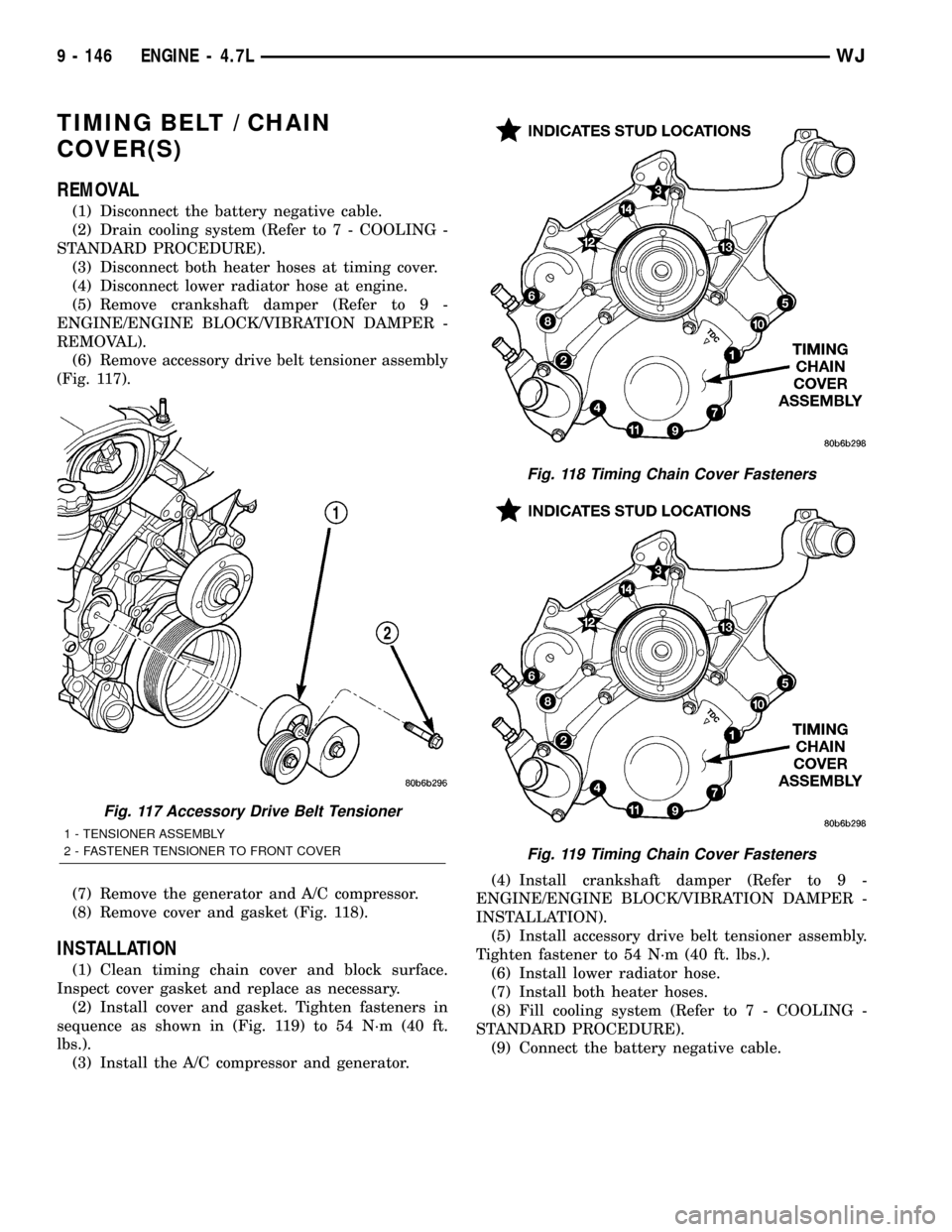
(6) Remove accessory drive belt tensioner assembly
(Fig. 117).
(7) Remove the generator and A/C compressor.
(8) Remove cover and gasket (Fig. 118).
INSTALLATION
(1) Clean timing chain cover and block surface.
Inspect cover gasket and replace as necessary.
(2) Install cover and gasket. Tighten fasteners in
sequence as shown in (Fig. 119) to 54 N´m (40 ft.
lbs.).
(3) Install the A/C compressor and generator.(4) Install crankshaft damper (Refer to 9 -
ENGINE/ENGINE BLOCK/VIBRATION DAMPER -
INSTALLATION).
(5) Install accessory drive belt tensioner assembly.
Tighten fastener to 54 N´m (40 ft. lbs.).
(6) Install lower radiator hose.
(7) Install both heater hoses.
(8) Fill cooling system (Refer to 7 - COOLING -
STANDARD PROCEDURE).
(9) Connect the battery negative cable.
Fig. 117 Accessory Drive Belt Tensioner
1 - TENSIONER ASSEMBLY
2 - FASTENER TENSIONER TO FRONT COVER
Fig. 118 Timing Chain Cover Fasteners
Fig. 119 Timing Chain Cover Fasteners
9 - 146 ENGINE - 4.7LWJ
Page 1509 of 2199
PUMP
DESCRIPTION - 4.0L, 4.7L
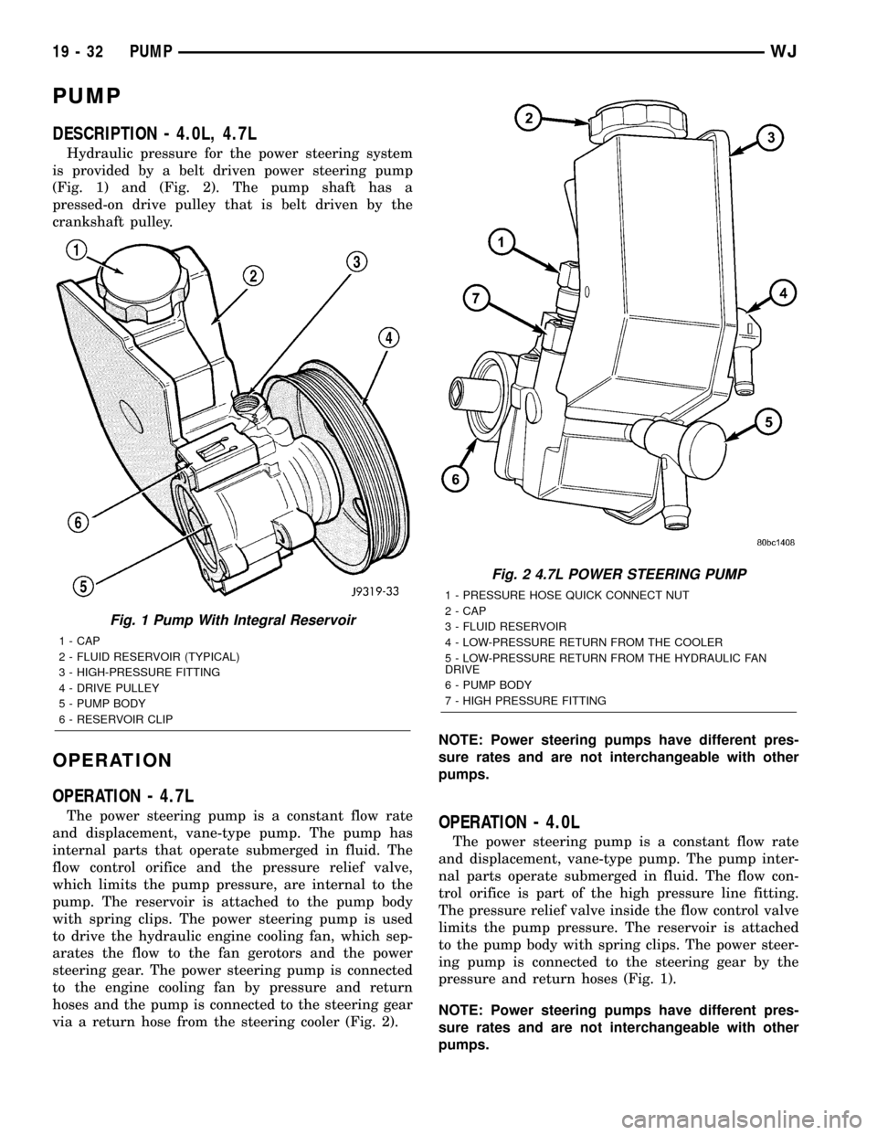
Hydraulic pressure for the power steering system
is provided by a belt driven power steering pump
(Fig. 1) and (Fig. 2). The pump shaft has a
pressed-on drive pulley that is belt driven by the
crankshaft pulley.
OPERATION
OPERATION - 4.7L
The power steering pump is a constant flow rate
and displacement, vane-type pump. The pump has
internal parts that operate submerged in fluid. The
flow control orifice and the pressure relief valve,
which limits the pump pressure, are internal to the
pump. The reservoir is attached to the pump body
with spring clips. The power steering pump is used
to drive the hydraulic engine cooling fan, which sep-
arates the flow to the fan gerotors and the power
steering gear. The power steering pump is connected
to the engine cooling fan by pressure and return
hoses and the pump is connected to the steering gear
via a return hose from the steering cooler (Fig. 2).NOTE: Power steering pumps have different pres-
sure rates and are not interchangeable with other
pumps.OPERATION - 4.0L
The power steering pump is a constant flow rate
and displacement, vane-type pump. The pump inter-
nal parts operate submerged in fluid. The flow con-
trol orifice is part of the high pressure line fitting.
The pressure relief valve inside the flow control valve
limits the pump pressure. The reservoir is attached
to the pump body with spring clips. The power steer-
ing pump is connected to the steering gear by the
pressure and return hoses (Fig. 1).
NOTE: Power steering pumps have different pres-
sure rates and are not interchangeable with other
pumps.
Fig. 1 Pump With Integral Reservoir
1 - CAP
2 - FLUID RESERVOIR (TYPICAL)
3 - HIGH-PRESSURE FITTING
4 - DRIVE PULLEY
5 - PUMP BODY
6 - RESERVOIR CLIP
Fig. 2 4.7L POWER STEERING PUMP
1 - PRESSURE HOSE QUICK CONNECT NUT
2 - CAP
3 - FLUID RESERVOIR
4 - LOW-PRESSURE RETURN FROM THE COOLER
5 - LOW-PRESSURE RETURN FROM THE HYDRAULIC FAN
DRIVE
6 - PUMP BODY
7 - HIGH PRESSURE FITTING
19 - 32 PUMPWJ
Page 1511 of 2199
(11) While the vehicle is in park, use the DRB III
to activate the hydraulic fan to full fan operation and
briefly rev the engine up to 3000 rpm to fully engage
the hydraulic fan.
(12) Check the fluid level add if necessary.
REMOVAL
REMOVAL - 4.0L ENGINE
(1) Remove serpentine drive belt,(Refer to 7 -
COOLING/ACCESSORY DRIVE/DRIVE BELTS -
REMOVAL).
(2) Remove pressure and return hoses from pump
and drain the pump.
(3)
Loosen the pump bracket bolt at the engine block.
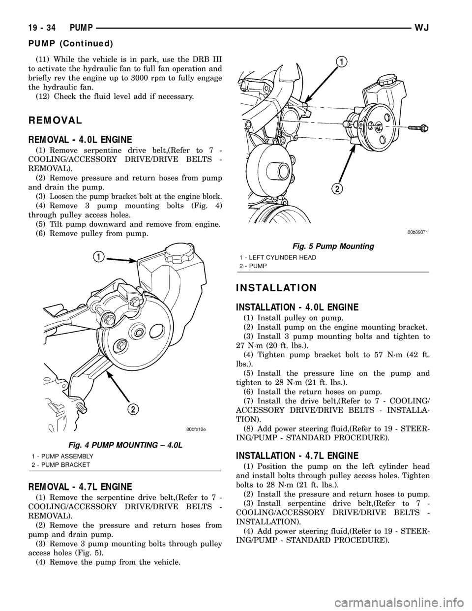
(4) Remove 3 pump mounting bolts (Fig. 4)
through pulley access holes.
(5) Tilt pump downward and remove from engine.
(6) Remove pulley from pump.
REMOVAL - 4.7L ENGINE
(1) Remove the serpentine drive belt,(Refer to 7 -
COOLING/ACCESSORY DRIVE/DRIVE BELTS -
REMOVAL).
(2) Remove the pressure and return hoses from
pump and drain pump.
(3) Remove 3 pump mounting bolts through pulley
access holes (Fig. 5).
(4) Remove the pump from the vehicle.
INSTALLATION
INSTALLATION - 4.0L ENGINE
(1) Install pulley on pump.
(2) Install pump on the engine mounting bracket.
(3) Install 3 pump mounting bolts and tighten to
27 N´m (20 ft. lbs.).
(4) Tighten pump bracket bolt to 57 N´m (42 ft.
lbs.).
(5) Install the pressure line on the pump and
tighten to 28 N´m (21 ft. lbs.).
(6) Install the return hoses on pump.
(7) Install the drive belt,(Refer to 7 - COOLING/
ACCESSORY DRIVE/DRIVE BELTS - INSTALLA-
TION).
(8) Add power steering fluid,(Refer to 19 - STEER-
ING/PUMP - STANDARD PROCEDURE).
INSTALLATION - 4.7L ENGINE
(1) Position the pump on the left cylinder head
and install bolts through pulley access holes. Tighten
bolts to 28 N´m (21 ft. lbs.).
(2) Install the pressure and return hoses to pump.
(3) Install serpentine drive belt,(Refer to 7 -
COOLING/ACCESSORY DRIVE/DRIVE BELTS -
INSTALLATION).
(4) Add power steering fluid,(Refer to 19 - STEER-
ING/PUMP - STANDARD PROCEDURE).
Fig. 4 PUMP MOUNTING ± 4.0L
1 - PUMP ASSEMBLY
2 - PUMP BRACKET
Fig. 5 Pump Mounting
1 - LEFT CYLINDER HEAD
2 - PUMP
19 - 34 PUMPWJ
PUMP (Continued)
Page 1519 of 2199
INSTALLATION
NOTE: The pulley is marked front for installation.
CAUTION: On vehicles equipped with the 4.0L or
4.7L, Do not reuse the old power steering pump
pulley it is not intended for reuse. A new pulley
must be installed if removed.
(1) Replace pulley if bent, cracked, or loose.
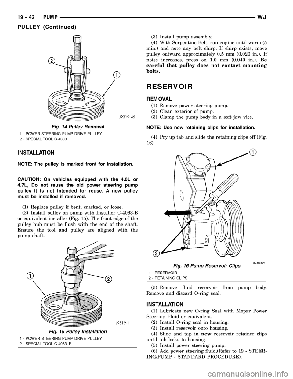
(2) Install pulley on pump with Installer C-4063-B
or equivalent installer (Fig. 15). The front edge of the
pulley hub must be flush with the end of the shaft.
Ensure the tool and pulley are aligned with the
pump shaft.(3) Install pump assembly.
(4) With Serpentine Belt, run engine until warm (5
min.) and note any belt chirp. If chirp exists, move
pulley outward approximately 0.5 mm (0.020 in.). If
noise increases, press on 1.0 mm (0.040 in.).Be
careful that pulley does not contact mounting
bolts.
RESERVOIR
REMOVAL
(1) Remove power steering pump.
(2) Clean exterior of pump.
(3) Clamp the pump body in a soft jaw vice.
NOTE: Use new retaining clips for installation.
(4) Pry up tab and slide the retaining clips off (Fig.
16).
(5) Remove fluid reservoir from pump body.
Remove and discard O-ring seal.
INSTALLATION
(1) Lubricate new O-ring Seal with Mopar Power
Steering Fluid or equivalent.
(2) Install O-ring seal in housing.
(3) Install reservoir onto housing.
(4) Slide and tap innewreservoir retainer clips
until tab locks to housing.
(5) Install power steering pump.
(6) Add power steering fluid,(Refer to 19 - STEER-
ING/PUMP - STANDARD PROCEDURE).
Fig. 14 Pulley Removal
1 - POWER STEERING PUMP DRIVE PULLEY
2 - SPECIAL TOOL C-4333
Fig. 15 Pulley Installation
1 - POWER STEERING PUMP DRIVE PULLEY
2 - SPECIAL TOOL C-4063±B
Fig. 16 Pump Reservoir Clips
1 - RESERVOIR
2 - RETAINING CLIPS
19 - 42 PUMPWJ
PULLEY (Continued)
Page 2082 of 2199
Pressure Diagnosis
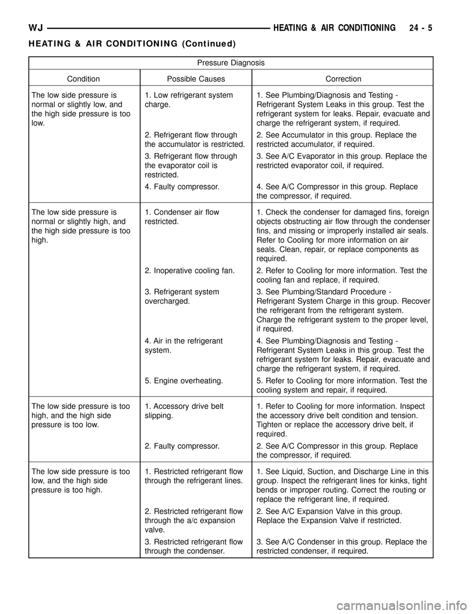
Condition Possible Causes Correction
The low side pressure is
normal or slightly low, and
the high side pressure is too
low.1. Low refrigerant system
charge.1. See Plumbing/Diagnosis and Testing -
Refrigerant System Leaks in this group. Test the
refrigerant system for leaks. Repair, evacuate and
charge the refrigerant system, if required.
2. Refrigerant flow through
the accumulator is restricted.2. See Accumulator in this group. Replace the
restricted accumulator, if required.
3. Refrigerant flow through
the evaporator coil is
restricted.3. See A/C Evaporator in this group. Replace the
restricted evaporator coil, if required.
4. Faulty compressor. 4. See A/C Compressor in this group. Replace
the compressor, if required.
The low side pressure is
normal or slightly high, and
the high side pressure is too
high.1. Condenser air flow
restricted.1. Check the condenser for damaged fins, foreign
objects obstructing air flow through the condenser
fins, and missing or improperly installed air seals.
Refer to Cooling for more information on air
seals. Clean, repair, or replace components as
required.
2. Inoperative cooling fan. 2. Refer to Cooling for more information. Test the
cooling fan and replace, if required.
3. Refrigerant system
overcharged.3. See Plumbing/Standard Procedure -
Refrigerant System Charge in this group. Recover
the refrigerant from the refrigerant system.
Charge the refrigerant system to the proper level,
if required.
4. Air in the refrigerant
system.4. See Plumbing/Diagnosis and Testing -
Refrigerant System Leaks in this group. Test the
refrigerant system for leaks. Repair, evacuate and
charge the refrigerant system, if required.
5. Engine overheating. 5. Refer to Cooling for more information. Test the
cooling system and repair, if required.
The low side pressure is too
high, and the high side
pressure is too low.1. Accessory drive belt
slipping.1. Refer to Cooling for more information. Inspect
the accessory drive belt condition and tension.
Tighten or replace the accessory drive belt, if
required.
2. Faulty compressor. 2. See A/C Compressor in this group. Replace
the compressor, if required.
The low side pressure is too
low, and the high side
pressure is too high.1. Restricted refrigerant flow
through the refrigerant lines.1. See Liquid, Suction, and Discharge Line in this
group. Inspect the refrigerant lines for kinks, tight
bends or improper routing. Correct the routing or
replace the refrigerant line, if required.
2. Restricted refrigerant flow
through the a/c expansion
valve.2. See A/C Expansion Valve in this group.
Replace the Expansion Valve if restricted.
3. Restricted refrigerant flow
through the condenser.3. See A/C Condenser in this group. Replace the
restricted condenser, if required.
WJHEATING & AIR CONDITIONING 24 - 5
HEATING & AIR CONDITIONING (Continued)
Page 2083 of 2199
DIAGNOSIS AND TESTING - HEATER
PERFORMANCE
Before performing the following tests, refer to Cool-
ing for the procedures to check the radiator coolant
level, serpentine drive belt tension, radiator air flow
and the radiator fan operation. Also be certain that
the accessory vacuum supply line is connected at the
engine intake manifold for the manual temperature
control system.
MAXIMUM HEATER OUTPUT
Engine coolant is delivered to the heater core
through two heater hoses. With the engine idling at
normal operating temperature, set the temperature
control knob in the full hot position, the mode control
switch knob in the floor heat position, and the blower
motor switch knob in the highest speed position.
Using a test thermometer, check the temperature of
the air being discharged at the HVAC housing floor
outlets. Compare the test thermometer reading to the
Temperature Reference chart.
Temperature Reference
Ambient Air Temperature15.5É C
(60É F)21.1É C
(70É F)26.6É C
(80É F)32.2É C
(90É F)
Minimum Air Temperature at
Floor Outlet62.2É C
(144É F)63.8É C
(147É F)65.5É C
(150É F)67.2É C
(153É F)
If the floor outlet air temperature is too low, refer
to Cooling to check the engine coolant temperature
specifications. Both of the heater hoses should be hot
to the touch. The coolant return heater hose should
be slightly cooler than the coolant supply heater
hose. If the return hose is much cooler than the sup-
ply hose, locate and repair the engine coolant flow
obstruction in the cooling system. Refer to Cooling
for the procedures.
OBSTRUCTED COOLANT FLOW
Possible locations or causes of obstructed coolant
flow:
²Pinched or kinked heater hoses.
²Improper heater hose routing.
²Plugged heater hoses or supply and return ports
at the cooling system connections.
²A plugged heater core.
If proper coolant flow through the cooling system is
verified, and heater outlet air temperature is still
low, a mechanical problem may exist.
MECHANICAL PROBLEMS
Possible locations or causes of insufficient heat:
²An obstructed cowl air intake.
²Obstructed heater system outlets.
²A blend door not functioning properly.
TEMPERATURE CONTROL
If the heater outlet air temperature cannot be
adjusted with the temperature control knob(s) on the
A/C Heater control panel, the following could require
service:
²The A/C heater control.
²The blend door actuator(s).
²The wire harness circuits for the A/C heater con-
trol or the blend door actuator(s).²The blend door(s).
²Improper engine coolant temperature.
STANDARD PROCEDURE - DIODE
REPLACEMENT
(1) Disconnect and isolate the negative battery
cable.
(2) Locate the diode in the harness, and remove
the protective covering.
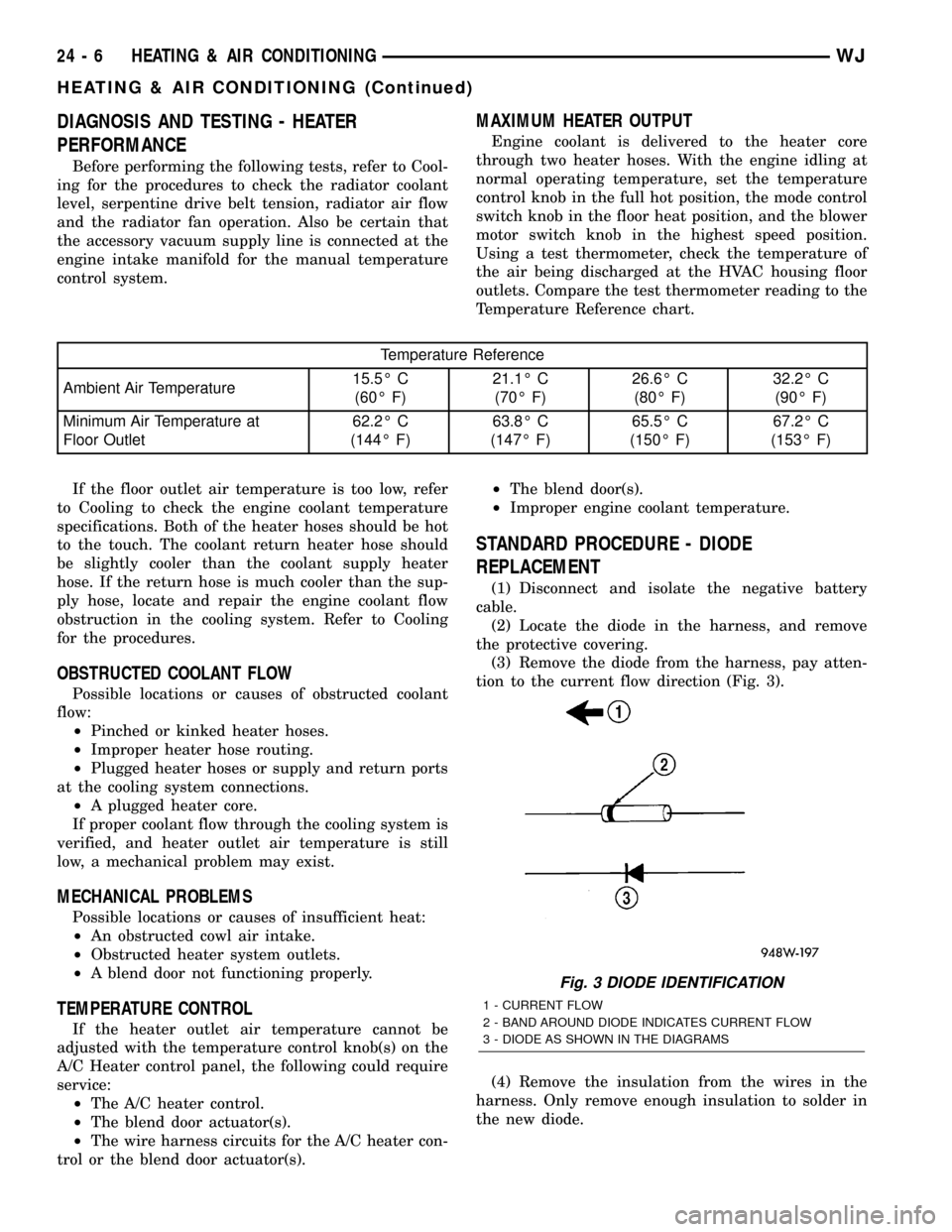
(3) Remove the diode from the harness, pay atten-
tion to the current flow direction (Fig. 3).
(4) Remove the insulation from the wires in the
harness. Only remove enough insulation to solder in
the new diode.
Fig. 3 DIODE IDENTIFICATION
1 - CURRENT FLOW
2 - BAND AROUND DIODE INDICATES CURRENT FLOW
3 - DIODE AS SHOWN IN THE DIAGRAMS
24 - 6 HEATING & AIR CONDITIONINGWJ
HEATING & AIR CONDITIONING (Continued)