2003 JEEP GRAND CHEROKEE oil system
[x] Cancel search: oil systemPage 12 of 2199

LUBRICATION & MAINTENANCE
TABLE OF CONTENTS
page page
LUBRICATION & MAINTENANCE
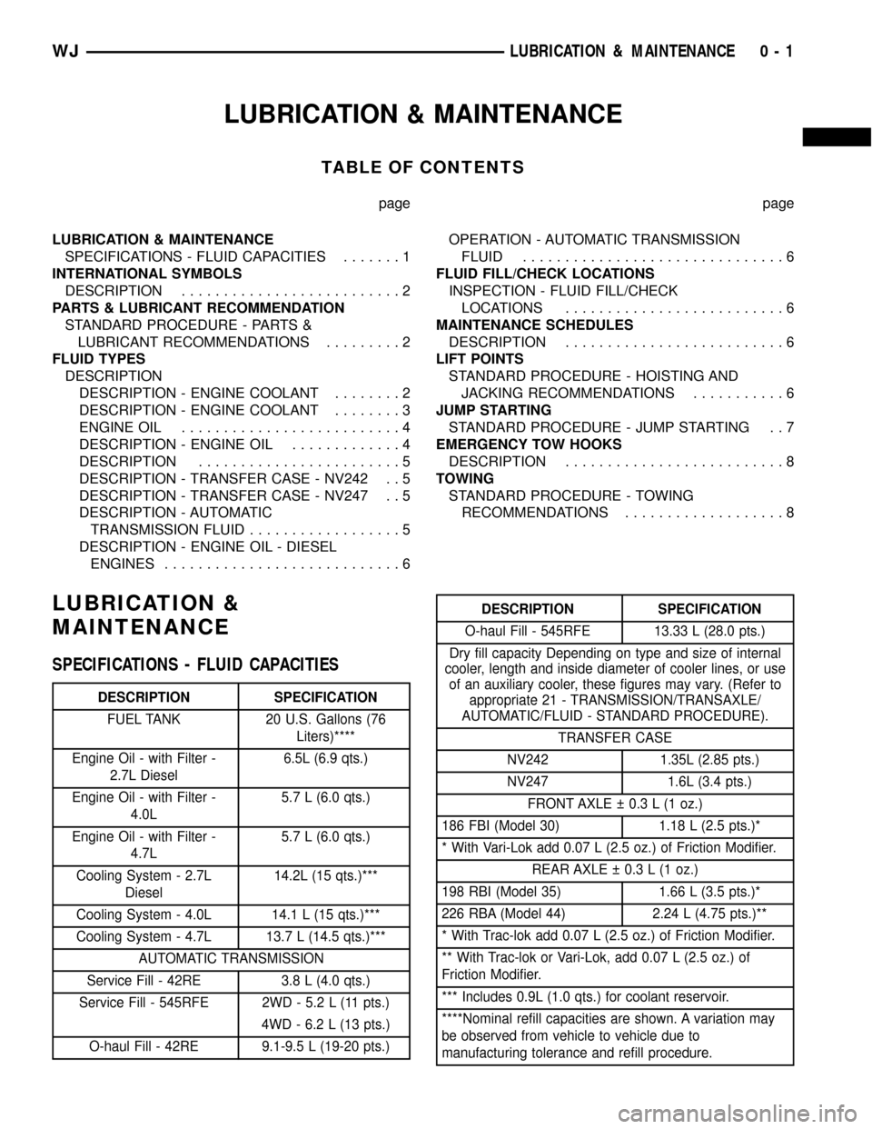
SPECIFICATIONS - FLUID CAPACITIES.......1
INTERNATIONAL SYMBOLS
DESCRIPTION..........................2
PARTS & LUBRICANT RECOMMENDATION
STANDARD PROCEDURE - PARTS &
LUBRICANT RECOMMENDATIONS.........2
FLUID TYPES
DESCRIPTION
DESCRIPTION - ENGINE COOLANT........2
DESCRIPTION - ENGINE COOLANT........3
ENGINE OIL..........................4
DESCRIPTION - ENGINE OIL.............4
DESCRIPTION........................5
DESCRIPTION - TRANSFER CASE - NV242 . . 5
DESCRIPTION - TRANSFER CASE - NV247 . . 5
DESCRIPTION - AUTOMATIC
TRANSMISSION FLUID..................5
DESCRIPTION - ENGINE OIL - DIESEL
ENGINES............................6OPERATION - AUTOMATIC TRANSMISSION
FLUID...............................6
FLUID FILL/CHECK LOCATIONS
INSPECTION - FLUID FILL/CHECK
LOCATIONS..........................6
MAINTENANCE SCHEDULES
DESCRIPTION..........................6
LIFT POINTS
STANDARD PROCEDURE - HOISTING AND
JACKING RECOMMENDATIONS...........6
JUMP STARTING
STANDARD PROCEDURE - JUMP STARTING . . 7
EMERGENCY TOW HOOKS
DESCRIPTION..........................8
TOWING
STANDARD PROCEDURE - TOWING
RECOMMENDATIONS...................8
LUBRICATION &
MAINTENANCE
SPECIFICATIONS - FLUID CAPACITIES
DESCRIPTION SPECIFICATION
FUEL TANK 20 U.S. Gallons (76
Liters)****
Engine Oil - with Filter -
2.7L Diesel6.5L (6.9 qts.)
Engine Oil - with Filter -
4.0L5.7 L (6.0 qts.)
Engine Oil - with Filter -
4.7L5.7 L (6.0 qts.)
Cooling System - 2.7L
Diesel14.2L (15 qts.)***
Cooling System - 4.0L 14.1 L (15 qts.)***
Cooling System - 4.7L 13.7 L (14.5 qts.)***
AUTOMATIC TRANSMISSION
Service Fill - 42RE 3.8 L (4.0 qts.)
Service Fill - 545RFE 2WD - 5.2 L (11 pts.)
4WD - 6.2 L (13 pts.)
O-haul Fill - 42RE 9.1-9.5 L (19-20 pts.)
DESCRIPTION SPECIFICATION
O-haul Fill - 545RFE 13.33 L (28.0 pts.)
Dry fill capacity Depending on type and size of internal
cooler, length and inside diameter of cooler lines, or use
of an auxiliary cooler, these figures may vary. (Refer to
appropriate 21 - TRANSMISSION/TRANSAXLE/
AUTOMATIC/FLUID - STANDARD PROCEDURE).
TRANSFER CASE
NV242 1.35L (2.85 pts.)
NV247 1.6L (3.4 pts.)
FRONT AXLE 0.3 L (1 oz.)
186 FBI (Model 30) 1.18 L (2.5 pts.)*
* With Vari-Lok add 0.07 L (2.5 oz.) of Friction Modifier.
REAR AXLE 0.3 L (1 oz.)
198 RBI (Model 35) 1.66 L (3.5 pts.)*
226 RBA (Model 44) 2.24 L (4.75 pts.)**
* With Trac-lok add 0.07 L (2.5 oz.) of Friction Modifier.
** With Trac-lok or Vari-Lok, add 0.07 L (2.5 oz.) of
Friction Modifier.
*** Includes 0.9L (1.0 qts.) for coolant reservoir.
****Nominal refill capacities are shown. A variation may
be observed from vehicle to vehicle due to
manufacturing tolerance and refill procedure.
WJLUBRICATION & MAINTENANCE 0 - 1
Page 13 of 2199

INTERNATIONAL SYMBOLS
DESCRIPTION
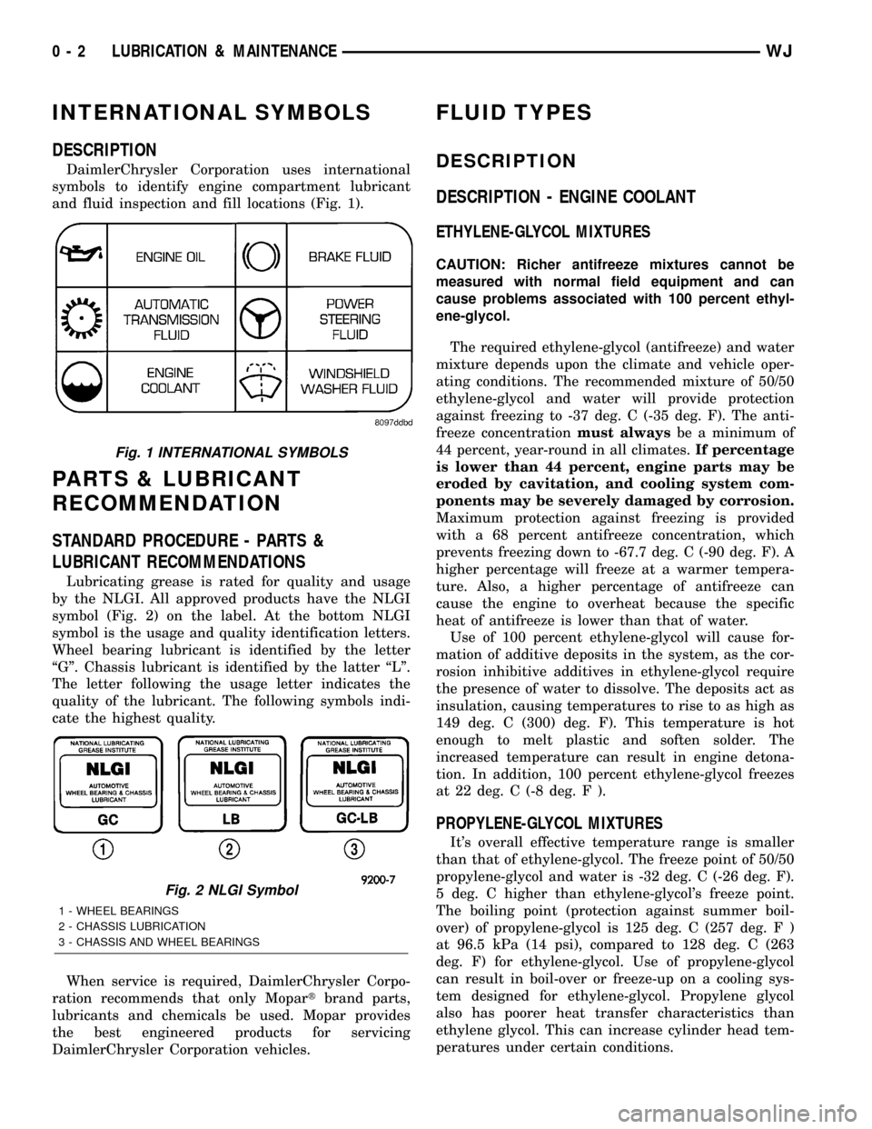
DaimlerChrysler Corporation uses international
symbols to identify engine compartment lubricant
and fluid inspection and fill locations (Fig. 1).
PARTS & LUBRICANT
RECOMMENDATION
STANDARD PROCEDURE - PARTS &
LUBRICANT RECOMMENDATIONS
Lubricating grease is rated for quality and usage
by the NLGI. All approved products have the NLGI
symbol (Fig. 2) on the label. At the bottom NLGI
symbol is the usage and quality identification letters.
Wheel bearing lubricant is identified by the letter
ªGº. Chassis lubricant is identified by the latter ªLº.
The letter following the usage letter indicates the
quality of the lubricant. The following symbols indi-
cate the highest quality.
When service is required, DaimlerChrysler Corpo-
ration recommends that only Mopartbrand parts,
lubricants and chemicals be used. Mopar provides
the best engineered products for servicing
DaimlerChrysler Corporation vehicles.
FLUID TYPES
DESCRIPTION
DESCRIPTION - ENGINE COOLANT
ETHYLENE-GLYCOL MIXTURES
CAUTION: Richer antifreeze mixtures cannot be
measured with normal field equipment and can
cause problems associated with 100 percent ethyl-
ene-glycol.
The required ethylene-glycol (antifreeze) and water
mixture depends upon the climate and vehicle oper-
ating conditions. The recommended mixture of 50/50
ethylene-glycol and water will provide protection
against freezing to -37 deg. C (-35 deg. F). The anti-
freeze concentrationmust alwaysbe a minimum of
44 percent, year-round in all climates.If percentage
is lower than 44 percent, engine parts may be
eroded by cavitation, and cooling system com-
ponents may be severely damaged by corrosion.
Maximum protection against freezing is provided
with a 68 percent antifreeze concentration, which
prevents freezing down to -67.7 deg. C (-90 deg. F). A
higher percentage will freeze at a warmer tempera-
ture. Also, a higher percentage of antifreeze can
cause the engine to overheat because the specific
heat of antifreeze is lower than that of water.
Use of 100 percent ethylene-glycol will cause for-
mation of additive deposits in the system, as the cor-
rosion inhibitive additives in ethylene-glycol require
the presence of water to dissolve. The deposits act as
insulation, causing temperatures to rise to as high as
149 deg. C (300) deg. F). This temperature is hot
enough to melt plastic and soften solder. The
increased temperature can result in engine detona-
tion. In addition, 100 percent ethylene-glycol freezes
at 22 deg. C (-8 deg. F ).
PROPYLENE-GLYCOL MIXTURES
It's overall effective temperature range is smaller
than that of ethylene-glycol. The freeze point of 50/50
propylene-glycol and water is -32 deg. C (-26 deg. F).
5 deg. C higher than ethylene-glycol's freeze point.
The boiling point (protection against summer boil-
over) of propylene-glycol is 125 deg. C (257 deg. F )
at 96.5 kPa (14 psi), compared to 128 deg. C (263
deg. F) for ethylene-glycol. Use of propylene-glycol
can result in boil-over or freeze-up on a cooling sys-
tem designed for ethylene-glycol. Propylene glycol
also has poorer heat transfer characteristics than
ethylene glycol. This can increase cylinder head tem-
peratures under certain conditions.
Fig. 1 INTERNATIONAL SYMBOLS
Fig. 2 NLGI Symbol
1 - WHEEL BEARINGS
2 - CHASSIS LUBRICATION
3 - CHASSIS AND WHEEL BEARINGS
0 - 2 LUBRICATION & MAINTENANCEWJ
Page 65 of 2199

Condition Possible Causes Correction
Axle Noise 1. Insufficient lubricant. 1. Fill differential with the correct
fluid type and quantity.
2. Improper ring gear and pinion
adjustment.2. Check ring gear and pinion
contact pattern.
3. Unmatched ring gear and pinion. 3. Replace gears with a matched
ring gear and pinion.
4. Worn teeth on ring gear and/or
pinion.4. Replace ring gear and pinion.
5. Loose pinion bearings. 5. Adjust pinion bearing pre-load.
6. Loose differential bearings. 6. Adjust differential bearing
pre-load.
7. Mis-aligned or sprung ring gear. 7. Measure ring gear run-out.
Replace components as necessary.
8. Loose differential bearing cap
bolts.8. Inspect differential components
and replace as necessary. Ensure
that the bearing caps are torqued
tot he proper specification.
9. Housing not machined properly. 9. Replace housing.
VARI-LOKT
(1) Park the vehicle on a level surface or raise
vehicle on hoist so that the vehicle is level.
(2) Remove the axle fill plug.
(3) Verify that the axle fluid level is correct. The
fluid level is correct if the fluid is level with the bot-
tom of the fill hole.
(4) Shift the transfer case into the 4WD full-time
position.
(5) Drive the vehicle in a tight circle for 2 minutes
at 5mph to fully prime the pump.
(6) Block the tires opposite the axle to be tested to
prevent the vehicle from moving.
(7) Shift the transfer case into the 4WD Low posi-
tion and the transmission into the Park position.
(8) Raise both the wheels of the axle to be tested
off of the ground.
(9) Rotate the left wheel by hand at a minimum of
one revolution per second while an assistant rotates
the right wheel in the opposite direction.
(10) The left wheel should spin freely at first and
then increase in resistance within 5 revolutions until
the wheels cannot be continuously rotated in opposite
directions.
(11) The Vari-loktdifferential has engaged prop-
erly if the wheels cannot be rotated in opposite direc-
tions for a moment. After the wheels stop rotating for
a moment, the fluid pressure will drop in the differ-
ential and the wheels begin to rotate once again.
(12) If the system does not operate properly,
replace the Vari-loktdifferential.
REMOVAL
(1) Raise and support the vehicle.
(2) Position a suitable lifting device under the
axle.
(3) Secure axle to lift.
(4) Remove the wheels and tires.
(5) Remove the brake calipers and rotors (Refer to
5 - BRAKES/HYDRAULIC/MECHANICAL/ROTORS
- REMOVAL) from the axle.
(6) Disconnect the wheel sensor wiring harness
from the vehicle wiring harness.
(7) Disconnect the vent hose from the axle shaft
tube.
(8) Mark propeller shaft and yoke/pinion flange for
installation alignment reference.
(9) Remove propeller shaft.
(10) Disconnect stabilizer bar links at the axle.
(11) Disconnect shock absorbers from axle brack-
ets.
(12) Disconnect track bar.
(13) Disconnect the tie rod and drag link from the
steering knuckle.
(14) Disconnect the steering damper from the axle
bracket.
(15) Disconnect the upper and lower suspension
arms from the axle brackets.
(16) Lower the lifting device enough to remove the
axle. The coil springs will drop with the axle.
(17) Remove the coil springs from the axle.
3 - 20 FRONT AXLE - 186FBIWJ
FRONT AXLE - 186FBI (Continued)
Page 179 of 2199

Common causes of brake drag are:
²Parking brake partially applied.
²Loose/worn wheel bearing.
²Seized caliper.
²Caliper binding.
²Loose caliper mounting.
²Mis-assembled components.
²Damaged brake lines.
If brake drag occurs at the front, rear or all
wheels, the problem may be related to a blocked mas-
ter cylinder return port, faulty power booster (binds-
does not release) or the ABS system.
BRAKE FADE
Brake fade is usually a product of overheating
caused by brake drag. However, brake overheating
and resulting fade can also be caused by riding the
brake pedal, making repeated high deceleration stops
in a short time span, or constant braking on steep
mountain roads. Refer to the Brake Drag information
in this section for causes.
BRAKE PULL
Front brake pull condition could result from:
²Contaminated lining in one caliper
²Seized caliper piston
²Binding caliper
²Loose caliper
²Rusty caliper slide surfaces
²Improper brake shoes
²Damaged rotor
²Wheel alignment.
²Tire pressure.
A worn, damaged wheel bearing or suspension compo-
nent are further causes of pull. A damaged front tire
(bruised, ply separation) can also cause pull.
A common and frequently misdiagnosed pull condi-
tion is where direction of pull changes after a few
stops. The cause is a combination of brake drag fol-
lowed by fade at one of the brake units.
As the dragging brake overheats, efficiency is so
reduced that fade occurs. Since the opposite brake
unit is still functioning normally, its braking effect is
magnified. This causes pull to switch direction in
favor of the normally functioning brake unit.
An additional point when diagnosing a change in
pull condition concerns brake cool down. Remember
that pull will return to the original direction, if the
dragging brake unit is allowed to cool down (and is
not seriously damaged).
REAR BRAKE DRAG OR PULL
Rear drag or pull may be caused by improperly
adjusted park brake shoes or seized parking brake
cables, contaminated lining, bent or binding shoes or
improperly assembled components. This is particu-
larly true when only one rear wheel is involved.However, when both rear wheels are affected, the
master cylinder or ABS system could be at fault.
BRAKES DO NOT HOLD AFTER DRIVING THROUGH DEEP
WATER PUDDLES
This condition is generally caused by water soaked
lining. If the lining is only wet, it can be dried by
driving with the brakes very lightly applied for a
mile or two. However, if the lining is both soaked and
dirt contaminated, cleaning and or replacement will
be necessary.
BRAKE LINING CONTAMINATION
Brake lining contamination is mostly a product of
leaking calipers or worn seals, driving through deep
water puddles, or lining that has become covered with
grease and grit during repair. Contaminated lining
should be replaced to avoid further brake problems.
WHEEL AND TIRE PROBLEMS
Some conditions attributed to brake components
may actually be caused by a wheel or tire problem.
A damaged wheel can cause shudder, vibration and
pull. A worn or damaged tire can also cause pull.
NOTE: Propshaft angle can also cause vibration/
shudder.
Severely worn tires with very little tread left can
produce a grab-like condition as the tire loses and
recovers traction. Flat-spotted tires can cause vibra-
tion and generate shudder during brake operation.
Tire damage such as a severe bruise, cut, ply separa-
tion, low air pressure can cause pull and vibration.
BRAKE NOISES
Some brake noise is common on some disc brakes
during the first few stops after a vehicle has been
parked overnight or stored. This is primarily due to
the formation of trace corrosion (light rust) on metal
surfaces. This light corrosion is typically cleared from
the metal surfaces after a few brake applications
causing the noise to subside.
BRAKE SQUEAK/SQUEAL
Brake squeak or squeal may be due to linings that
are wet or contaminated with brake fluid, grease, or oil.
Glazed linings and rotors with hard spots can also con-
tribute to squeak. Dirt and foreign material embedded
in the brake lining will also cause squeak/squeal.
A very loud squeak or squeal is frequently a sign of
severely worn brake lining. If the lining has worn
through to the brake shoes in spots, metal-to-metal
contact occurs. If the condition is allowed to continue,
rotors may become so scored that replacement is nec-
essary.
5 - 4 BRAKES - BASEWJ
BRAKES - BASE (Continued)
Page 183 of 2199

ADJUSTABLE PEDAL SWITCH
REMOVAL
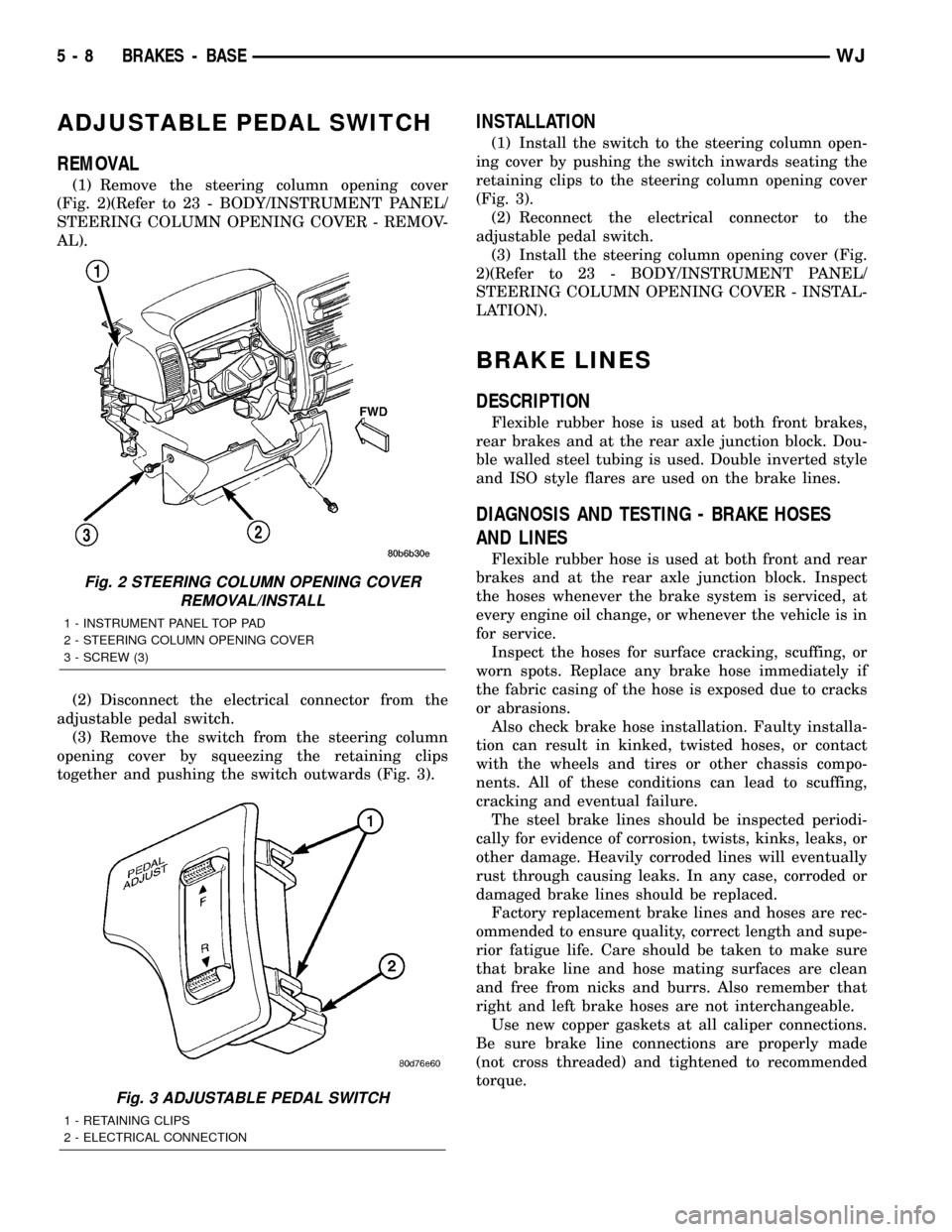
(1) Remove the steering column opening cover
(Fig. 2)(Refer to 23 - BODY/INSTRUMENT PANEL/
STEERING COLUMN OPENING COVER - REMOV-
AL).
(2) Disconnect the electrical connector from the
adjustable pedal switch.
(3) Remove the switch from the steering column
opening cover by squeezing the retaining clips
together and pushing the switch outwards (Fig. 3).
INSTALLATION
(1) Install the switch to the steering column open-
ing cover by pushing the switch inwards seating the
retaining clips to the steering column opening cover
(Fig. 3).
(2) Reconnect the electrical connector to the
adjustable pedal switch.
(3) Install the steering column opening cover (Fig.
2)(Refer to 23 - BODY/INSTRUMENT PANEL/
STEERING COLUMN OPENING COVER - INSTAL-
LATION).
BRAKE LINES
DESCRIPTION
Flexible rubber hose is used at both front brakes,
rear brakes and at the rear axle junction block. Dou-
ble walled steel tubing is used. Double inverted style
and ISO style flares are used on the brake lines.
DIAGNOSIS AND TESTING - BRAKE HOSES
AND LINES
Flexible rubber hose is used at both front and rear
brakes and at the rear axle junction block. Inspect
the hoses whenever the brake system is serviced, at
every engine oil change, or whenever the vehicle is in
for service.
Inspect the hoses for surface cracking, scuffing, or
worn spots. Replace any brake hose immediately if
the fabric casing of the hose is exposed due to cracks
or abrasions.
Also check brake hose installation. Faulty installa-
tion can result in kinked, twisted hoses, or contact
with the wheels and tires or other chassis compo-
nents. All of these conditions can lead to scuffing,
cracking and eventual failure.
The steel brake lines should be inspected periodi-
cally for evidence of corrosion, twists, kinks, leaks, or
other damage. Heavily corroded lines will eventually
rust through causing leaks. In any case, corroded or
damaged brake lines should be replaced.
Factory replacement brake lines and hoses are rec-
ommended to ensure quality, correct length and supe-
rior fatigue life. Care should be taken to make sure
that brake line and hose mating surfaces are clean
and free from nicks and burrs. Also remember that
right and left brake hoses are not interchangeable.
Use new copper gaskets at all caliper connections.
Be sure brake line connections are properly made
(not cross threaded) and tightened to recommended
torque.
Fig. 2 STEERING COLUMN OPENING COVER
REMOVAL/INSTALL
1 - INSTRUMENT PANEL TOP PAD
2 - STEERING COLUMN OPENING COVER
3 - SCREW (3)
Fig. 3 ADJUSTABLE PEDAL SWITCH
1 - RETAINING CLIPS
2 - ELECTRICAL CONNECTION
5 - 8 BRAKES - BASEWJ
Page 198 of 2199

rates into layers, there is mineral oil or other fluid
contamination of the brake fluid.
If brake fluid is contaminated, drain and thor-
oughly flush system. Replace master cylinder with
reservoir, caliper seals, HCU and all hydraulic fluid
hoses.
SPECIFICATIONS
BRAKE FLUID
The brake fluid used in this vehicle must conform
to DOT 3 specifications and SAE J1703 standards.
No other type of brake fluid is recommended or
approved for usage in the vehicle brake system. Use
only Mopar brake fluid or an equivalent from a
tightly sealed container.
CAUTION: Never use reclaimed brake fluid or fluid
from an container which has been left open. An
open container of brake fluid will absorb moisture
from the air and contaminate the fluid.
CAUTION: Never use any type of a petroleum-based
fluid in the brake hydraulic system. Use of such
type fluids will result in seal damage of the vehicle
brake hydraulic system causing a failure of the
vehicle brake system. Petroleum based fluids would
be items such as engine oil, transmission fluid,
power steering fluid, etc.
FLUID RESERVOIR
REMOVAL
(1) Remove reservoir cap and remove fluid with a
cleansuction gun.
(2) Remove the wire connector from the brake fluid
level sensor.
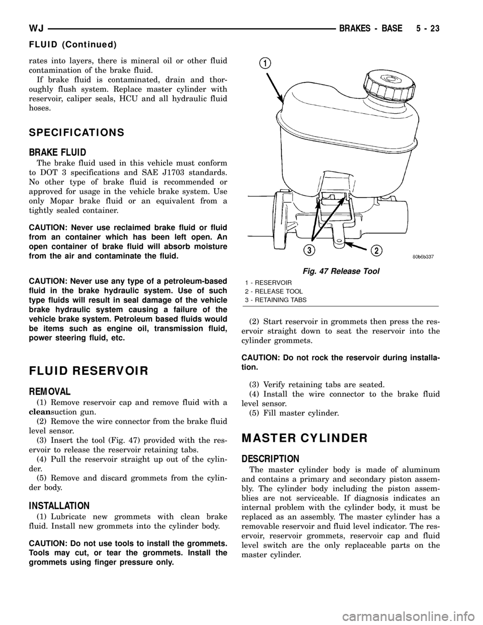
(3) Insert the tool (Fig. 47) provided with the res-
ervoir to release the reservoir retaining tabs.
(4) Pull the reservoir straight up out of the cylin-
der.
(5) Remove and discard grommets from the cylin-
der body.
INSTALLATION
(1) Lubricate new grommets with clean brake
fluid. Install new grommets into the cylinder body.
CAUTION: Do not use tools to install the grommets.
Tools may cut, or tear the grommets. Install the
grommets using finger pressure only.(2) Start reservoir in grommets then press the res-
ervoir straight down to seat the reservoir into the
cylinder grommets.
CAUTION: Do not rock the reservoir during installa-
tion.
(3) Verify retaining tabs are seated.
(4) Install the wire connector to the brake fluid
level sensor.
(5) Fill master cylinder.
MASTER CYLINDER
DESCRIPTION
The master cylinder body is made of aluminum
and contains a primary and secondary piston assem-
bly. The cylinder body including the piston assem-
blies are not serviceable. If diagnosis indicates an
internal problem with the cylinder body, it must be
replaced as an assembly. The master cylinder has a
removable reservoir and fluid level indicator. The res-
ervoir, reservoir grommets, reservoir cap and fluid
level switch are the only replaceable parts on the
master cylinder.
Fig. 47 Release Tool
1 - RESERVOIR
2 - RELEASE TOOL
3 - RETAINING TABS
WJBRAKES - BASE 5 - 23
FLUID (Continued)
Page 224 of 2199

COOLING
TABLE OF CONTENTS
page page
COOLING
DESCRIPTION
DESCRIPTION - COOLING SYSTEM 4.7L
ENGINE..............................1
DESCRIPTION - COOLING SYSTEM
ROUTING 4.7L ENGINE..................1
DESCRIPTIONÐCOOLING SYSTEM 4.0L
ENGINE..............................1
DESCRIPTIONÐCOOLING SYSTEM
ROUTING 4.0L ENGINE..................1
DESCRIPTIONÐHOSE CLAMPS...........1
OPERATION
OPERATIONÐCOOLING SYSTEM.........2
OPERATIONÐHOSE CLAMPS............2
DIAGNOSIS AND TESTING
DIAGNOSIS AND TESTINGÐON-BOARD
DIAGNOSTICS (OBD)...................3
DIAGNOSIS AND TESTINGÐPRELIMINARY
CHECKS.............................3
DIAGNOSIS AND TESTING - COOLING
SYSTEM DIAGNOSIS CHART.............5
DIAGNOSIS AND TESTING - COOLING
SYSTEM LEAKS......................10DIAGNOSIS AND TESTING - COOLING
SYSTEM DEAERATION.................12
STANDARD PROCEDURE
STANDARD PROCEDUREÐDRAINING
COOLING SYSTEM 4.7L ENGINE.........12
STANDARD PROCEDURE - REFILLING
COOLING SYSTEM 4.7L ENGINE.........12
STANDARD PROCEDURE - DRAINING
COOLING SYSTEM - 4.0L ENGINE........13
STANDARD PROCEDURE - REFILLING
COOLING SYSTEM - 4.0L ENGINE........13
STANDARD PROCEDURE - ADDING
ADDITIONAL COOLANT.................13
STANDARD PROCEDURE - COOLING
SYSTEM - REVERSE FLUSHING..........14
SPECIFICATIONS
TORQUE............................14
SPECIAL TOOLS
COOLING...........................15
ACCESSORY DRIVE......................16
ENGINE...............................24
TRANSMISSION.........................55
COOLING
DESCRIPTION
DESCRIPTION - COOLING SYSTEM 4.7L
ENGINE
The cooling system consists of the following items:
²Hydraulic cooling fan and fan drive assembly
²Radiator
²Power steering oil cooler
²Radiator pressure cap
²Thermostat
²Coolant reserve/overflow system
²Transmission oil cooler (if equipped with an
automatic transmission)
²Coolant
²Water pump
²Hoses and hose clamps
DESCRIPTION - COOLING SYSTEM ROUTING
4.7L ENGINE
For cooling system routing refer to (Fig. 1).
DESCRIPTIONÐCOOLING SYSTEM 4.0L
ENGINE
The cooling system consists of:
²A radiator
²Mechanical Cooling Fan
²Thermal viscous fan drive-Low disengaged
²Fan shroud (Fig. 2)
²Radiator pressure cap
²Thermostat
²Coolant reserve/overflow system
²Transmission oil cooler (if equipped with an
automatic transmission)
²Coolant
²Water pump
²Hoses and hose clamps
²Accessory drive belt
DESCRIPTIONÐCOOLING SYSTEM ROUTING
4.0L ENGINE
For cooling system routing refer to (Fig. 3).
DESCRIPTIONÐHOSE CLAMPS
The cooling system utilizes both worm drive and
spring type hose clamps. If a spring type clamp
WJCOOLING 7 - 1
Page 228 of 2199

DIAGNOSIS AND TESTING - COOLING SYSTEM DIAGNOSIS CHART
COOLING SYSTEM DIAGNOSIS CHART
CONDITION POSSIBLE CAUSES CORRECTION
TEMPERATURE GAUGE
READS LOW1. Has a Diagnostic Trouble Code
(DTC) been set indicating a stuck
open thermostat?1. Refer to (Refer to 25 - EMISSIONS
CONTROL - DESCRIPTION) for On-Board
Diagnostics and DTC information. Replace
thermostat if necessary.
2. Is the temperature sending unit
connected?2. Check the temperature sensor connector.
(Refer to 7 - COOLING/ENGINE/ENGINE
COOLANT TEMP SENSOR -
DESCRIPTION). Repair connector if
necessary.
3. Is the temperature gauge
operating OK?3. Check gauge operation. Repair as
necessary.
4. Coolant level low in cold ambient
temperatures accompanied with
poor heater performance.4. Check coolant level in the coolant
reserve/overflow tank and the radiator.
Inspect system for leaks. Repair leaks as
necessary.
5. Improper operation of internal
heater doors or heater controls.5. Inspect heater and repair as necessary.
(Refer to 24 - HEATING & AIR
CONDITIONING - DIAGNOSIS AND
TESTING)
TEMPERATURE GAUGE
READS HIGH OR THE
COOLANT LAMP
ILLUMINATES.
COOLANT MAY OR MAY
NOT BE LOST OR
LEAKING FROM THE
COOLING SYSTEM1. Trailer is being towed, a steep hill
is being climbed, vehicle is operated
in slow moving traffic, or engine is
being idled with very high ambient
(outside) temperatures and the air
conditioning is on. Higher altitudes
could aggravate these conditions.1. This may be a temporary condition and
repair is not necessary. Turn off the air
conditioning and attempt to drive the vehicle
without any of the previous conditions.
Observe the temperature gauge. The gauge
should return to the normal range. If the
gauge does not return to the normal range,
determine the cause for overheating and
repair.
2. Is the temperature gauge reading
correctly?2. Check gauge. (Refer to Group 8J -
INSTRUMENT CLUSTER). Repair as
necessary.
3. Is the temperature warning
illuminating unnecessarily?3. Check warning lamp operation. (Refer to
Group 8J - INSTRUMENT CLUSTER).Repair
as necessary.
4. Coolant low in coolant reserve/
overflow tank and radiator?4. Check for coolant leaks and repair as
necessary. (Refer to 7 - COOLING -
DIAGNOSIS AND TESTING).
5. Pressure cap not installed tightly.
If cap is loose, boiling point of
coolant will be lowered. Also refer to
the following Step 6.5. Tighten cap
WJCOOLING 7 - 5
COOLING (Continued)