2003 INFINITI G35 key
[x] Cancel search: keyPage 104 of 256

1. Pull the hood lock release handle
j 1
lo-
cated below the instrument panel; the hood
will then spring up slightly.
2. Raise the lever
j 2
at the front of the hood
with your fingertips and raise the hood.
3. Insert the assist bar into the slot
j 3
in the
front edge of the hood.
4. When closing the hood, reset the assist bar
to its original position, then slowly close the
hood and make sure it locks into place.
WARNING O Make sure the hood is completely
closed and latched before driving.
Failure to do so could cause the hood
to fly open and result in an accident.
O If you see steam or smoke coming
from the engine compartment, to
avoid injury do not open the hood. WARNING O Do not drive with the trunk lid open.
This could allow dangerous exhaust
gases to be drawn into the vehicle.
See ªPrecautions when starting and
drivingº in the ª5. Starting and driv-
ingº section for exhaust gas.
O Closely supervise children when they
are around cars to prevent them from
playing and becoming locked in the
trunk where they could be seriously
injured. Keep the car locked with the
trunk closed when not in use, and
prevent children's access to car keys. SPA1423
HOOD TRUNK LID
3-10 Pre-driving checks and adjustments
Z 02.7.29/V35-D/V5.0
X
Page 105 of 256
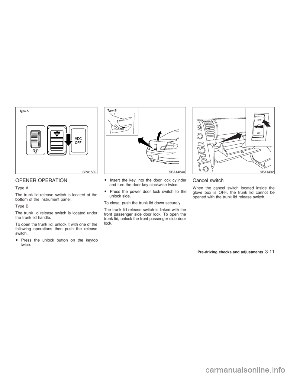
OPENER OPERATION Type A
The trunk lid release switch is located at the
bottom of the instrument panel.
Type B
The trunk lid release switch is located under
the trunk lid handle.
To open the trunk lid, unlock it with one of the
following operations then push the release
switch.
O Press the unlock button on the keyfob
twice. O Insert the key into the door lock cylinder
and turn the door key clockwise twice.
O Press the power door lock switch to the
unlock side.
To close, push the trunk lid down securely.
The trunk lid release switch is linked with the
front passenger side door lock. To open the
trunk lid, unlock the front passenger side door
lock. Cancel switch When the cancel switch located inside the
glove box is OFF, the trunk lid cannot be
opened with the trunk lid release switch.SPA1589 SPA1424A SPA1432
Pre-driving checks and adjustments
3-11
Z 02.7.29/V35-D/V5.0
X
Page 106 of 256
INTERIOR TRUNK LID RELEASE
WARNINGClosely supervise children when they
are around cars to prevent them from
playing and becoming locked in the
trunk where they could be seriously in-
jured. Keep the car locked, with the
trunk closed, when not in use, and pre-
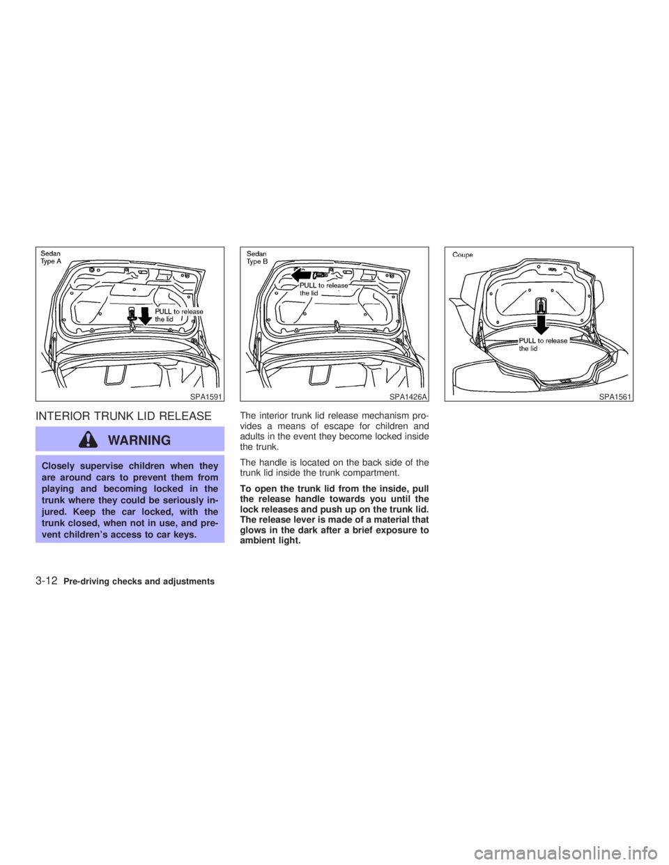
vent children's access to car keys. The interior trunk lid release mechanism pro-
vides a means of escape for children and
adults in the event they become locked inside
the trunk.
The handle is located on the back side of the
trunk lid inside the trunk compartment.
To open the trunk lid from the inside, pull
the release handle towards you until the
lock releases and push up on the trunk lid.
The release lever is made of a material that
glows in the dark after a brief exposure to
ambient light.SPA1591 SPA1426A SPA1561
3-12 Pre-driving checks and adjustments
Z 02.7.29/V35-D/V5.0
X
Page 108 of 256
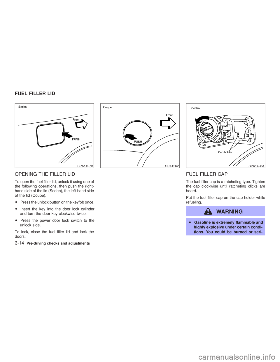
OPENING THE FILLER LID To open the fuel filler lid, unlock it using one of
the following operations, then push the right-
hand side of the lid (Sedan), the left-hand side
of the lid (Coupe).
O Press the unlock button on the keyfob once.
O Insert the key into the door lock cylinder
and turn the door key clockwise twice.
O Press the power door lock switch to the
unlock side.
To lock, close the fuel filler lid and lock the
doors. FUEL FILLER CAP The fuel filler cap is a ratcheting type. Tighten
the cap clockwise until ratcheting clicks are
heard.
Put the fuel filler cap on the cap holder while
refueling.
WARNING O Gasoline is extremely flammable and
highly explosive under certain condi-
tions. You could be burned or seri-SPA1427B SPA1562 SPA1428A
FUEL FILLER LID
3-14 Pre-driving checks and adjustments
Z 02.7.29/V35-D/V5.0
X
Page 113 of 256
AUTOMATIC SEAT POSITIONER
OPERATION This system is designed so that the driver's
seat will automatically move when the auto-
matic transmission selector lever is in the P
(Park) position or when the parking brake is
applied (manual transmission model). This al-
lows the driver to get in and out of the driver's
seat more easily.
When one of the following conditions is met,
the driver's seat will slide backward. (AT mod-
els only)
O When the key is removed from the ignition
switch.
O When the driver's door is opened with the
key turned to ACC or LOCK.
O When the key is turned from ON to ACC
with the driver's door open.
When one of the following conditions is met,
the driver's seat will return to the positions
before being set. (AT models only)
O When the key is inserted into the ignition
switch.
O When the driver's door is closed with the
key turned to LOCK.
O When the key is turned from ACC to ON with the driver's door open.
PROCEDURE FOR STORING
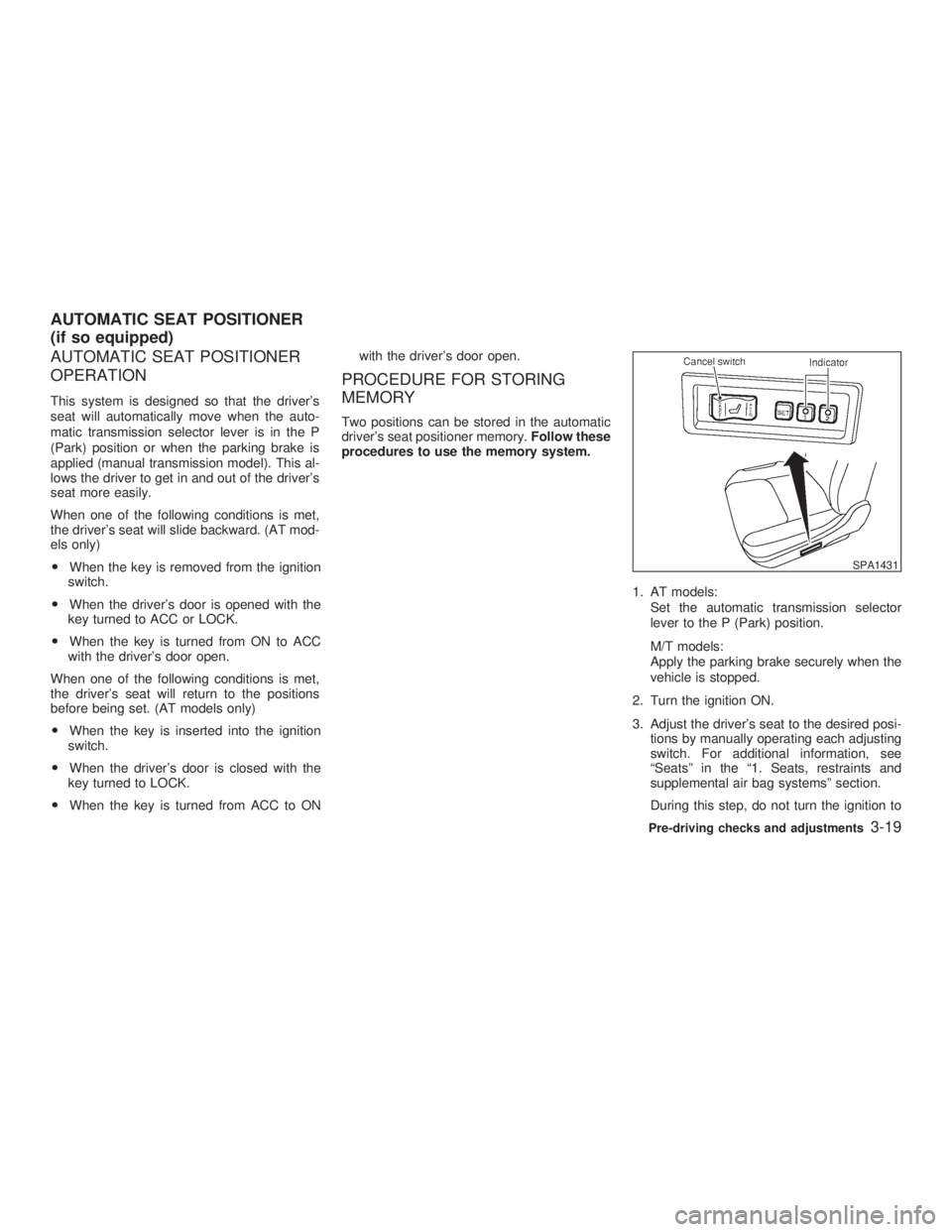
MEMORY Two positions can be stored in the automatic
driver's seat positioner memory. Follow these
procedures to use the memory system.
1. AT models:
Set the automatic transmission selector
lever to the P (Park) position.
M/T models:
Apply the parking brake securely when the
vehicle is stopped.
2. Turn the ignition ON.
3. Adjust the driver's seat to the desired posi-
tions by manually operating each adjusting
switch. For additional information, see
ªSeatsº in the ª1. Seats, restraints and
supplemental air bag systemsº section.
During this step, do not turn the ignition to SPA1431
AUTOMATIC SEAT POSITIONER
(if so equipped)
Pre-driving checks and adjustments
3-19
Z 02.7.29/V35-D/V5.0
X
Page 114 of 256

any positions other than ON.
4. Push the SET switch and, within 5 seconds,
push the memory switch 1 or 2 fully for at
least 1 second.
The indicator light for the pushed memory
switch will come on and stay on for approxi-
mately 5 seconds after pushing the switch.
After the indicator light goes off, the se-
lected positions are stored in the selected
memory (1 or 2).
If memory is stored in the same memory
switch, the previous memory will be de-
leted.
Confirming memory storage O Turn the ignition ON and push the SET
switch. If the main memory has not been
stored, the indicator light will come on for
approximately 0.5 seconds. When the
memory has stored the position, the indica-
tor light will stay on for approximately 5
seconds.
O If the battery cable is disconnected, or if the
fuse blows, the memory will be canceled. In
such a case, reset the desired positions
using the following procedures.
1. Open and close the driver's door more than two times with the ignition key in the LOCK
position.
2. Reset the desired position using the previ-
ous procedure.
Selecting the memorized position 1. A/T models:
Set the automatic transmission selector le-
ver to the P (Park) position.
M/T models:
Apply the parking brake securely when the
vehicle is stopped.
2. Turn the ignition ON.
3. Push the memory switch 1 or 2 fully for at
least 1 second.
The driver's seat will move to the memo-
rized position with the indicator light flash-
ing. Then the light will stay on for approxi-
mately 5 seconds.
When memory switch 1 or 2 is pushed with the
driver's door open and then the key inserted
into the ignition switch within approximately 1
minute, the driver's seat will move to the
memorized position. (AT models only) System operation The automatic drive positioner system will not
work or will stop operating under the following
conditions:
O when the vehicle speed is above 4 MPH (7
km/h).
O when any two or more of the memory
switches are simultaneously pressed while
the automatic drive positioner is operating.
O when the adjusting switch for the driver's
seat is turned on while the automatic drive
positioner is operating.
O when the cancel switch is pushed to cancel.
O when the memory switch 1 or 2 is not
pushed for at least 1 second.
O when the seat has already been moved to
the memorized position.
O when no seat position is stored in the
memory switch.
O when the parking brake is not applied. Ð
M/T models
O when the vehicle speed is above 4 MPH (7
km/h) while the parking brake is applied. Ð
M/T models
To restart the drive positioner system,
move the parking brake to off and on.
3-20 Pre-driving checks and adjustments
Z 02.7.29/V35-D/V5.0
X
Page 122 of 256
up easily when operating the heater or air
conditioning system. The air conditioning system in your INFINITI
vehicle is charged with a refrigerant designed
with the environment in mind. This refrigerant
will not harm the earth's ozone layer. How-
ever, special charging equipment and lubricant
are required when servicing your NISSAN air
conditioner. Using improper refrigerants or lu-
bricants will cause severe damage to your air
conditioning system. See ªCapacities and rec-
ommended fuel/lubricantsº in the ª10. Techni-
cal and consumer informationº section for air
conditioning system refrigerant and lubricant
recommendations.
Your INFINITI retailer will be able to service
your environmentally friendly air conditioning
system.
WARNING The air conditioner system contains re-
frigerant under high pressure. To avoid
personal injury, any air conditioner ser-
vice should be done only by an experi-
enced technician with proper equip-
ment. Turn the ignition key to ACC or ON and press
the POWER, FM or AM button to turn on the
radio. If you listen to the radio with the engine
not running, the key should be turned to the
ACC position.
Radio reception is affected by station signal
strength, distance from radio transmitter, build-
ings, bridges, mountains and other external
influences. Intermittent changes in reception
quality normally are caused by these external
influences.
Using a cellular phone in or near the ve-
hicle may influence radio reception quality.
Radio reception Your radio system is equipped with state-of-
the-art electronic circuits to enhance radio
reception. These circuits are designed to ex-
tend reception range, and to enhance the
quality of that reception.
However there are some general characteris-
tics of FM, AM and satellite radio signals that
can affect radio reception quality in a moving
vehicle, even when the finest equipment is
used. These characteristics are completely
normal in a given reception area, and do not
indicate any malfunction in your radio system.
Remember that a moving vehicle is not the
ideal place to listen to a radio. Because of theSERVICING AIR CONDITIONER AUDIO SYSTEM
4-6 Heater, air conditioner and audio systems
Z 02.7.29/V35-D/V5.0
X
Page 127 of 256
FM-AM-SATELLITE RADIO WITH
CASSETTE PLAYER AND
COMPACT DISC (CD) CHANGER
Audio main operation Head unit:
The radio has an FM diversity reception sys-
tem, which employs two antennas printed on
the rear window. This system automatically
switches to the antenna which is receiving less
interference.
The tape deck employs a permalloy head
which allows for improved reproduction of high
frequency ranges. Noise is also greatly re-
duced by the combined use of the Dolby NR
(Noise Reduction) system. The auto loudness
circuit enhances the low frequency range au-
tomatically in both radio reception and tape
and CD playback.
POWER on/off:
Turn the ignition key to ACC or ON, and then
push the POWER on/off button while the sys-
tem is off to call up the mode (radio, tape or
CD) which was playing immediately before the
system was turned off. When no CD or tape is
loaded, the radio will come on. While the
system is on, pushing the POWER on/off
button turns the system off. Volume control:
Push the volume control button (VOL)
(down) or (up) to adjust the vol-
ume.
This vehicle has Speed sensitive Control
Volume (SCV) for audio . The audio volume
changes as the driving speed changes.
AUDIO button (BASS, TREBLE, FADER,
BALANCE, SCV and NR (Dolby)):
Press the AUDIO button to change the select-
ing mode as follows.
BASS ! TREBLE ! FADER ! BALANCE !
SCV ! NR (when cassette playing) ! (Nor-
mal) ! BASS
To adjust Bass, Treble, Fader and Balance,
press the AUDIO button until the desired mode
BASS, TREBLE, FADER or BALANCE ap-
pears in the display. Press the TUNE (
or ) button to adjust Bass and Treble to
the desired level. Use the or button
also to adjust Fader or Balance modes. Fader
adjusts the sound level between the front and
rear speakers and Balance adjusts the sound
between the right and left speakers.
To change the SCV mode to OFF, LOW, MID
or HIGH, press the or (TUNE) but-
ton. To change the NR (Dolby) mode to OFF or
ON, press the or (TUNE) button
while cassette tape is playing. When Dolby is
ON, the display indicates the mark.
After 10 seconds, the radio, cassette tape or
CD display reappears. Once the sound quality
is set to the desired level, press the AUDIO
button repeatedly until the radio, cassette tape
or CD display appears.
Dolby noise reduction manufactured under li-
cense from Dolby Laboratories Licensing Cor-
poration. Dolby NR and the double-D symbol
are trademarks of Dolby Laboratories
Licensing Corporation.
Metal or chrome tape usage:
The cassette player will be automatically set to
high performance play when playing a metal or
chrome cassette tape.
FM-AM radio operation FM/AM band select:
Pushing the FM/AM band select button will
change the band as follows:
AM ! FM1 ! FM2 ! AM
When FM/AM band select button is pushed
while the ignition switch is in the ACC or ON,
Heater, air conditioner and audio systems
4-11
Z 02.7.29/V35-D/V5.0
X