2003 INFINITI G35 display
[x] Cancel search: displayPage 54 of 256

2 Instruments and controls Instrument panel ....................................................... 2-2
Meters and gauges ................................................... 2-3
Speedometer and odometer ................................ 2-4
Tachometer .......................................................... 2-4
Engine coolant temperature gauge ...................... 2-5
Fuel gauge ........................................................... 2-5
Compass display ...................................................... 2-6
Warning/indicator lights and audible reminders ........ 2-9
Checking bulbs ..................................................... 2-9
Warning lights....................................................... 2-9
Indicator lights .................................................... 2-11
Audible reminders .............................................. 2-13
Security systems ..................................................... 2-13
Vehicle security system ...................................... 2-13
Infiniti Vehicle Immobilizer System ................... 2-14
Windshield wiper and washer switch ...................... 2-16
Rear window and outside mirror (if so equipped)
defroster switch ....................................................... 2-16
Headlight and turn signal switch ............................. 2-17
Xenon headlights (if so equipped) ..................... 2-17
Headlight switch ................................................. 2-17
Turn signal switch .............................................. 2-19
Fog light switch ....................................................... 2-20
Hazard warning flasher switch ................................ 2-20 Horn......................................................................... 2-21
Heated seats (if so equipped) ................................. 2-21
Vehicle dynamics control (VDC) off switch ............ 2-22
Clock ....................................................................... 2-23
Adjusting the time............................................... 2-23
Power outlet ............................................................ 2-23
Cigarette lighter and ashtray (accessory) ............... 2-24
Storage .................................................................... 2-25
Instrument pocket (Except for Navigation system
equipped models) ............................................... 2-25
Pocket (Manual transmission model) ................. 2-25
Glasses case ...................................................... 2-26
Cup holder .......................................................... 2-26
Glove box ........................................................... 2-27
Upper glove box (Except for Navigation system
equipped models) ............................................... 2-28
Console box ....................................................... 2-28
Rear armrest pocket ........................................... 2-29
Cargo net............................................................ 2-29
Coat hook (Coupe) ............................................. 2-30
Stowing golf bags ............................................... 2-30
Windows .................................................................. 2-31
Power windows .................................................. 2-31
Automatic adjusting function (Coupe) ................ 2-33
Z 02.7.29/V35-D/V5.0
X
Page 56 of 256

1. Headlight, fog light and turn signal switch
(P.2-17)
2. Steering switch for audio control (P.4-16)
3. Driver supplemental air bag (P.1-8)/Horn
(P.2-21)
4. Meters/gauges (P.2-3) 5. Cruise control main/set switch (P.5-11)
6. Windshield wiper/washer switch (P.2-16)
7. Center ventilator (P.4-2)
8. Center display - Compass (P.2-6), Air con-
ditioner (P.2-6), Ambient temperature
(P.2-6) 9. Rear window and outside mirror (if so
equipped) defogger switch (P.2-16)
10. Heater/air conditioner control (P.4-3)
11. Clock (P.2-23)
12. Navigation system* (if so equipped)
13. Security indicator light (P.2-14)
14. Passenger supplemental air bag (P.1-8)
15. Upper glove box (Except for Navigation
system equipped models) (P.2-26)
16. Side window defroster
17. Side ventilator (P.4-2)
18. Hood lock release handle (P.3-9)
19. Instrument brightness control switch
(P.2-19)
20. Trunk lid release switch (P.3-11)
21. VDC (Vehicle Dynamics Control) OFF
switch (P.2-22)
22. Outside mirror remote control (P.3-15)
23. Fuse box (P.8-20)
24. Tilting steering wheel lock lever (P.3-14)
25. Ignition switch/steering lock (P.5-4)
26. Cigarette lighter (P.2-24)
27. Ashtray (P.2-24)/Pocket
28. Radio/cassette player (P.4-8)/CD player
(P.4-8)
29. Hazard warning flasher switch (P.2-20)
30. Heated seat switch (P.2-21)
31. Power outlet
32. Glove box (P.2-26) SIC2023INSTRUMENT PANEL
2-2 Instruments and controls
Z 02.7.29/V35-D/V5.0
X
Page 58 of 256

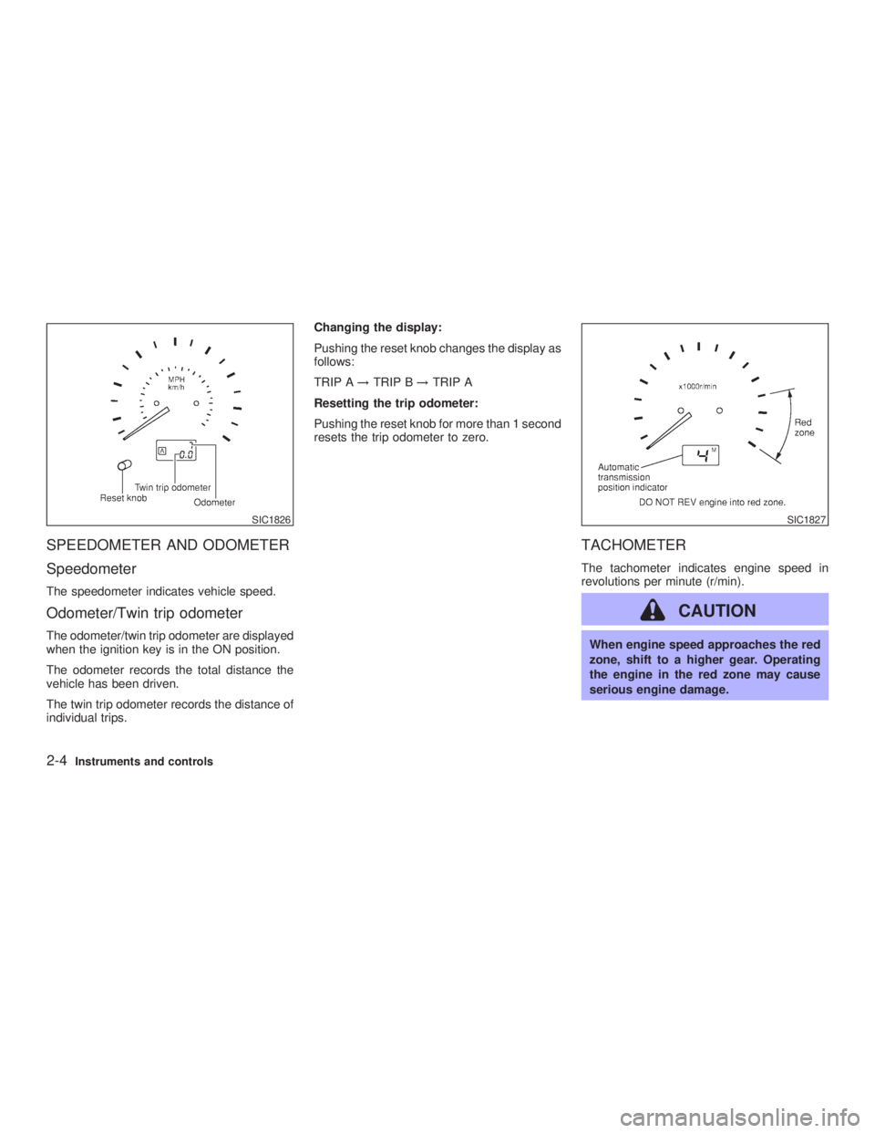
SPEEDOMETER AND ODOMETER
Speedometer The speedometer indicates vehicle speed.
Odometer/Twin trip odometer The odometer/twin trip odometer are displayed
when the ignition key is in the ON position.
The odometer records the total distance the
vehicle has been driven.
The twin trip odometer records the distance of
individual trips. Changing the display:
Pushing the reset knob changes the display as
follows:
TRIP A ! TRIP B ! TRIP A
Resetting the trip odometer:
Pushing the reset knob for more than 1 second
resets the trip odometer to zero.
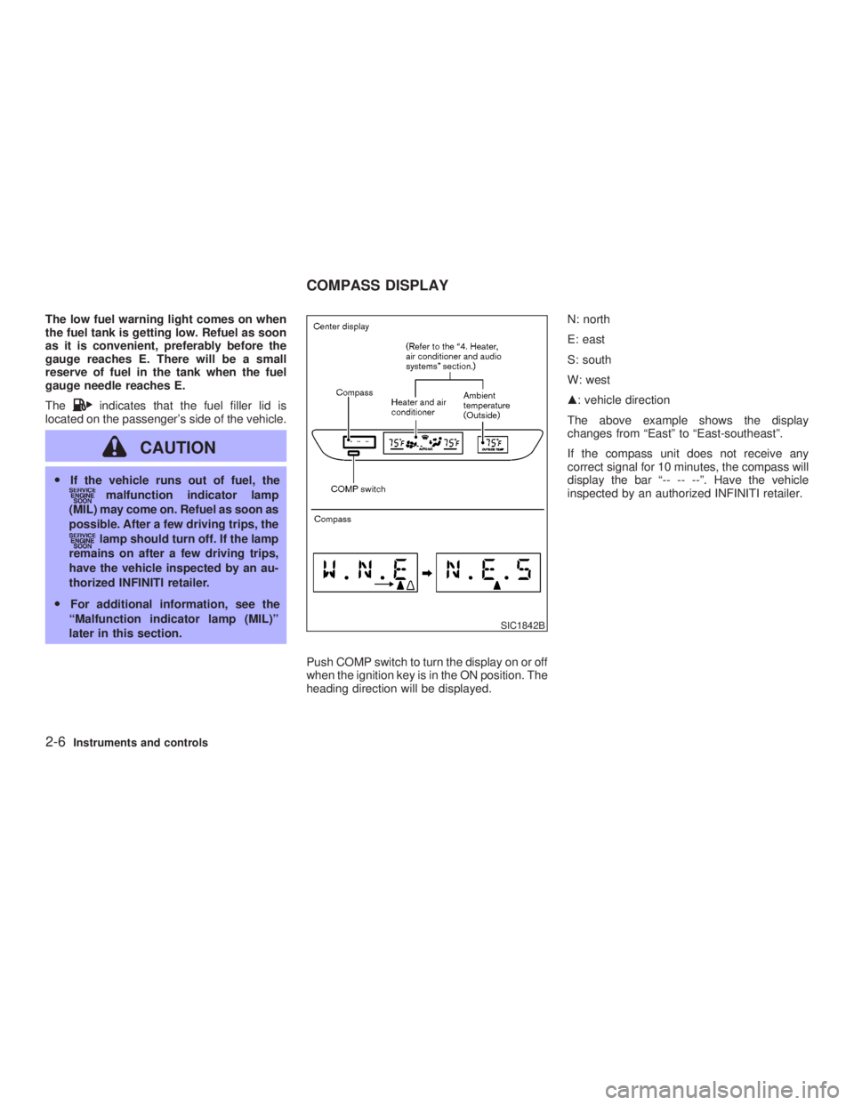
TACHOMETER The tachometer indicates engine speed in
revolutions per minute (r/min).
CAUTION When engine speed approaches the red
zone, shift to a higher gear. Operating
the engine in the red zone may cause
serious engine damage.SIC1826 SIC1827
2-4 Instruments and controls
Z 02.7.29/V35-D/V5.0
X
Page 60 of 256

The low fuel warning light comes on when
the fuel tank is getting low. Refuel as soon
as it is convenient, preferably before the
gauge reaches E. There will be a small
reserve of fuel in the tank when the fuel
gauge needle reaches E.
The indicates that the fuel filler lid is
located on the passenger's side of the vehicle.
CAUTIONO If the vehicle runs out of fuel, the
malfunction indicator lamp
(MIL) may come on. Refuel as soon as
possible. After a few driving trips, the
lamp should turn off. If the lamp
remains on after a few driving trips,
have the vehicle inspected by an au-
thorized INFINITI retailer.
O For additional information, see the
ªMalfunction indicator lamp (MIL)º
later in this section.
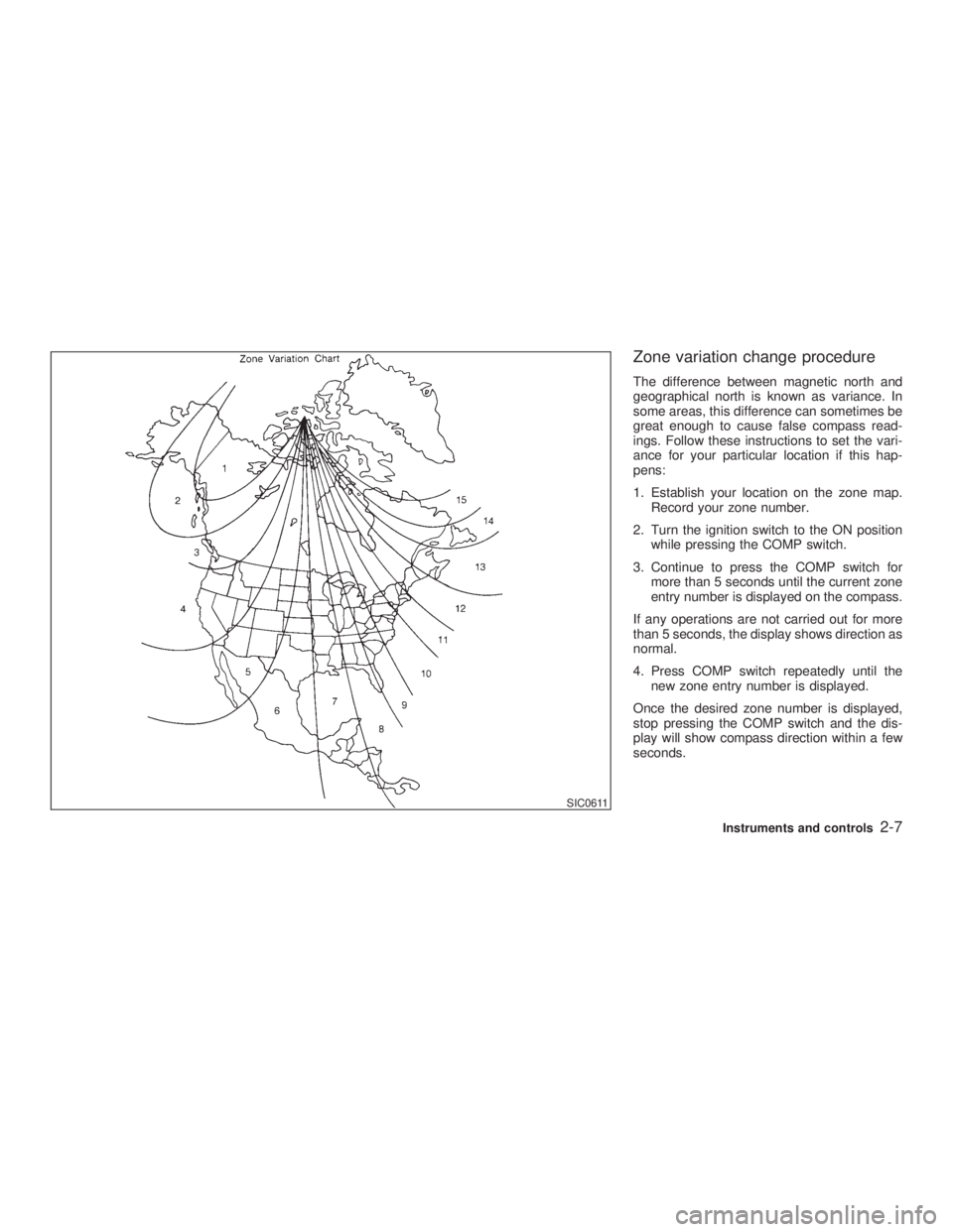
Push COMP switch to turn the display on or off
when the ignition key is in the ON position. The
heading direction will be displayed. N: north
E: east
S: south
W: west
m : vehicle direction
The above example shows the display
changes from ªEastº to ªEast-southeastº.
If the compass unit does not receive any
correct signal for 10 minutes, the compass will
display the bar ª-- -- --º. Have the vehicle
inspected by an authorized INFINITI retailer.
SIC1842BCOMPASS DISPLAY
2-6 Instruments and controls
Z 02.7.29/V35-D/V5.0
X
Page 61 of 256

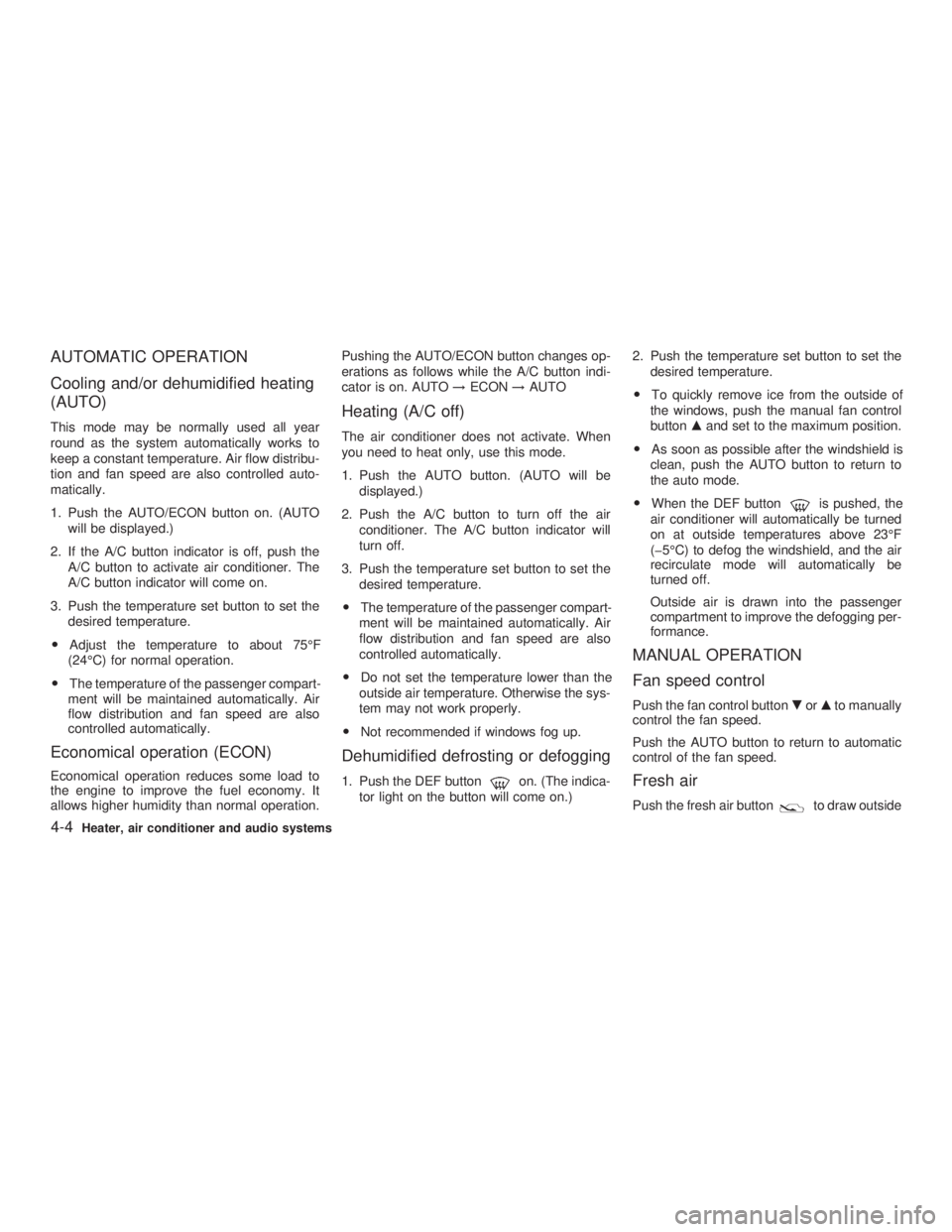
Zone variation change procedure The difference between magnetic north and
geographical north is known as variance. In
some areas, this difference can sometimes be
great enough to cause false compass read-
ings. Follow these instructions to set the vari-
ance for your particular location if this hap-
pens:
1. Establish your location on the zone map.
Record your zone number.
2. Turn the ignition switch to the ON position
while pressing the COMP switch.
3. Continue to press the COMP switch for
more than 5 seconds until the current zone
entry number is displayed on the compass.
If any operations are not carried out for more
than 5 seconds, the display shows direction as
normal.
4. Press COMP switch repeatedly until the
new zone entry number is displayed.
Once the desired zone number is displayed,
stop pressing the COMP switch and the dis-
play will show compass direction within a few
seconds. SIC0611
Instruments and controls
2-7
Z 02.7.29/V35-D/V5.0
X
Page 62 of 256

If a magnet is located near the driver side
instrument panel (the sensor is located
inside) or the vehicle is driven where the
terrestrial magnetism is disturbed, the
compass display may not indicate the cor-
rect direction.
O The compass may not display correctly at
the following places:
² under a bridge
² among buildings
² on an iron bridge
² inside a tunnel
² above a subway
² on a railway crossing
² in an underground parking lot
² near a huge vehicle
² near a transformer substation
If you carry out correction procedure at one
of the above places, the procedure may not
be completed correctly.
O If air conditioner fan speed is maximum, the
compass display may shake. This is nor-
mal. Reduce the fan speed to avoid shaking
the display.
Correction functions of the compass
display If the direction is not shown correctly, carry out
correction procedure set out below. Correction procedure 1. Push COMP switch for about 10 seconds.
The direction bar starts blinking.
2. Turn off electrical equipment such as lights,
hazard indicator, air conditioner, etc. Then
drive the vehicle slowly (less than 3 MPH (5
km/h)) and turn the vehicle one or more
times in an open and safe area. When the
compass displays the direction, the proce-
dure is completed.
2-8 Instruments and controls
Z 02.7.29/V35-D/V5.0
X
Page 120 of 256

AUTOMATIC OPERATION
Cooling and/or dehumidified heating
(AUTO) This mode may be normally used all year
round as the system automatically works to
keep a constant temperature. Air flow distribu-
tion and fan speed are also controlled auto-
matically.
1. Push the AUTO/ECON button on. (AUTO
will be displayed.)
2. If the A/C button indicator is off, push the
A/C button to activate air conditioner. The
A/C button indicator will come on.
3. Push the temperature set button to set the
desired temperature.
O Adjust the temperature to about 75ÉF
(24ÉC) for normal operation.
O The temperature of the passenger compart-
ment will be maintained automatically. Air
flow distribution and fan speed are also
controlled automatically.
Economical operation (ECON) Economical operation reduces some load to
the engine to improve the fuel economy. It
allows higher humidity than normal operation. Pushing the AUTO/ECON button changes op-
erations as follows while the A/C button indi-
cator is on. AUTO ! ECON ! AUTO
Heating (A/C off) The air conditioner does not activate. When
you need to heat only, use this mode.
1. Push the AUTO button. (AUTO will be
displayed.)
2. Push the A/C button to turn off the air
conditioner. The A/C button indicator will
turn off.
3. Push the temperature set button to set the
desired temperature.
O The temperature of the passenger compart-
ment will be maintained automatically. Air
flow distribution and fan speed are also
controlled automatically.
O Do not set the temperature lower than the
outside air temperature. Otherwise the sys-
tem may not work properly.
O Not recommended if windows fog up.
Dehumidified defrosting or defogging 1. Push the DEF button on. (The indica-
tor light on the button will come on.) 2. Push the temperature set button to set the
desired temperature.
O To quickly remove ice from the outside of
the windows, push the manual fan control
button m and set to the maximum position.
O As soon as possible after the windshield is
clean, push the AUTO button to return to
the auto mode.
O When the DEF button is pushed, the
air conditioner will automatically be turned
on at outside temperatures above 23ÉF
(þ5ÉC) to defog the windshield, and the air
recirculate mode will automatically be
turned off.
Outside air is drawn into the passenger
compartment to improve the defogging per-
formance.
MANUAL OPERATION
Fan speed control Push the fan control button . or m to manually
control the fan speed.
Push the AUTO button to return to automatic
control of the fan speed.
Fresh air Push the fresh air button to draw outside
4-4 Heater, air conditioner and audio systems
Z 02.7.29/V35-D/V5.0
X
Page 121 of 256

air into the passenger compartment. The indi-
cator light on the button will come on.
Air recirculation Push the air recirculation button to recir-
culate interior air inside the vehicle. The indi-
cator light on the button will come on.
The air recirculation button will not be acti-
vated when the air conditioner is in DEF mode.
Air flow control (MODE) Pushing the MODE button selects the air outlet
to:
: Air flows from center and side ventila-
tors.
: Air flows from center and side ventila-
tors and foot outlets.
: Air flows mainly from foot outlets.
: Air flows from defroster and foot out-
lets.
To turn the system off Push the OFF button.
DUAL ZONE BUTTON (if so
equipped) You can set the temperature of the driver and front passenger sides individually.
Pushing the DUAL zone button changes the
setting position as follows:
Driver/Passenger ! Driver ! Passenger
If selecting the Driver/Passenger position
again after the temperature is individually set,
the display will show the temperature set for
the driver side.
AMBIENT TEMPERATURE The outside ambient temperature will be
shown on the center display.
The ambient temperature sensor is located in
front of the radiator. The sensor may be af-
fected by road or engine heat, wind direction
and other driving conditions. The display may
differ from the actual outside temperature or
the temperature displayed on various signs or
billboards.
OPERATING TIPS When the engine coolant temperature and
outside air temperature are low, the air flow
from the foot outlets may not operate for a
maximum of 150 seconds. However, this is not
a malfunction. After the coolant temperature
warms up, the air flow from the foot outlets will
operate normally. The sensor on the instrument panel helps
maintain a constant temperature; do not put
anything on or around this sensor.
IN-CABIN MICROFILTER The air conditioning system is equipped with a
in-cabin microfilter which collects dirt, pollen,
dust, etc. To make sure air conditioner heats,
defogs, and ventilates efficiently, replace the
filter in accordance with the maintenance
schedule in this manual. To replace the filter,
contact your INFINITI retailer.
The filter should be replaced if air flow
decreases significantly or if windows fog HA1011
Heater, air conditioner and audio systems
4-5
Z 02.7.29/V35-D/V5.0
X