2003 Hyundai H-1 (Grand Starex) lock
[x] Cancel search: lockPage 119 of 173

IN CASE OF EMERGENCY
IN CASE OF EMERGENCY IN CASE OF EMERGENCY
IN CASE OF EMERGENCY
IN CASE OF EMERGENCY
4-4
E050A01P-GAT SPARE WHEEL (If installed)
SPARE WHEEL (If installed) SPARE WHEEL (If installed)
SPARE WHEEL (If installed)
SPARE WHEEL (If installed) E050B01P-GAT
To reinstall the spare tire
To reinstall the spare tire To reinstall the spare tire
To reinstall the spare tire
To reinstall the spare tire 1. Set the spare tire on the center of the hanger. 2. Raise the hanger and hook it onto the holder.
CAUTION:
CAUTION: CAUTION:
CAUTION:
CAUTION:
The spare wheel should always be securely
The spare wheel should always be securely The spare wheel should always be securely
The spare wheel should always be securely
The spare wheel should always be securely
in position.
in position. in position.
in position.
in position.
If a flat tire is changed, put the flat tire in the
If a flat tire is changed, put the flat tire in the If a flat tire is changed, put the flat tire in the
If a flat tire is changed, put the flat tire in the
If a flat tire is changed, put the flat tire in the
spare wheel mounting position, and use the
spare wheel mounting position, and use the spare wheel mounting position, and use the
spare wheel mounting position, and use the
spare wheel mounting position, and use the
wheel nut wrench to secure it firmly.
wheel nut wrench to secure it firmly. wheel nut wrench to secure it firmly.
wheel nut wrench to secure it firmly.
wheel nut wrench to secure it firmly. E050C01P-GAT
SPARE WHEEL (TRUCK)
SPARE WHEEL (TRUCK) SPARE WHEEL (TRUCK)
SPARE WHEEL (TRUCK)
SPARE WHEEL (TRUCK)
E050C01P
1. Connect the spare wheel carrier wrench with the wheel nut wrench.
2. Insert the spare wheel carrier wrench into the hole in the spare tire carrier then turn the wheel nut wrench counterclockwise, and thespare tire comes down.
E050C02P
steel wire
hook
tire support
E050A02P
Check the air pressure of the spare tire fre-
quently and make sure it is ready for emer- gency use at any time.
Maintaining the spare wheel at the highest
specified air pressure will ensure that it canalways be used under any conditions (city/-high-speed driving, varying load weight, etc.).
The spare wheel is stored under the floor of the
cargo space.
To remove the spare wheel, follow the proce-
dures described below.
1. Use the wheel nut wrench to loosen the holder mounting bolt.
2. Lift up the hanger and separate it from the holder, and then lower the hanger and re- move the spare tire.
E050B02P
Page 120 of 173

IN CASE OF EMERGENCY
IN CASE OF EMERGENCY IN CASE OF EMERGENCY
IN CASE OF EMERGENCY
IN CASE OF EMERGENCY
4-5
3. Disconnect the steel wire from the tire sup-port hook after the spare tire comes down completely.
4. To install the spare tire, build the spare tire as following.
E050C03P
E050C04P
5. Connect the steel wire with the support hook. 6. Insert the spare wheel carrier wrench into
the hole in the spare tire carrier then turn the wheel nut wrench clockwise.
7. After the spare tire fully raised, tighten by hand to about 30 kg f (295 N).
Then, remove the spare wheel carrier wrenchwith care not to turn it in the reverse direc-tion. Now, ensure that the tire is secured inposition.
CAUTION:
CAUTION: CAUTION:
CAUTION:
CAUTION:
If you cannot secure the spare tire in posi-
If you cannot secure the spare tire in posi- If you cannot secure the spare tire in posi-
If you cannot secure the spare tire in posi-
If you cannot secure the spare tire in posi- tion, load it on the cargo deck and ask your
tion, load it on the cargo deck and ask your tion, load it on the cargo deck and ask your
tion, load it on the cargo deck and ask your
tion, load it on the cargo deck and ask your
nearest service shop for inspection.
nearest service shop for inspection. nearest service shop for inspection.
nearest service shop for inspection.
nearest service shop for inspection.
E050C05P
rear wheel tire
wheel carrier guide
front wheel tire tire support
hook
tire support
steel wire
E050D01P-GAT
SPARE TIRE ANTI-THEFT DEVICE
SPARE TIRE ANTI-THEFT DEVICE SPARE TIRE ANTI-THEFT DEVICE
SPARE TIRE ANTI-THEFT DEVICE
SPARE TIRE ANTI-THEFT DEVICE
(If installed)
(If installed) (If installed)
(If installed)
(If installed)
FFT903C
Latch plate
Spare wheel carrier mount-ing bracket
This device is designed to protect the spare tire
theft. After fitting the latch plate hole in spare wheel
carrier mounting bracket with a spare wheelcarrier wrench, lock with a key bought person-ally.
Page 123 of 173

IN CASE OF EMERGENCY
IN CASE OF EMERGENCY IN CASE OF EMERGENCY
IN CASE OF EMERGENCY
IN CASE OF EMERGENCY
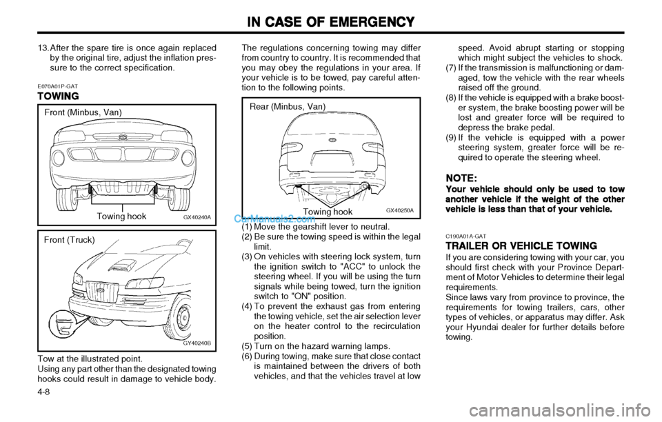
4-8 The regulations concerning towing may differ from country to country. It is recommended thatyou may obey the regulations in your area. Ifyour vehicle is to be towed, pay careful atten-tion to the following points.
C190A01A-GATTRAILER OR VEHICLE TOWING
TRAILER OR VEHICLE TOWING TRAILER OR VEHICLE TOWING
TRAILER OR VEHICLE TOWING
TRAILER OR VEHICLE TOWING
If you are considering towing with your car, youshould first check with your Province Depart-ment of Motor Vehicles to determine their legal requirements.Since laws vary from province to province, the requirements for towing trailers, cars, othertypes of vehicles, or apparatus may differ. Askyour Hyundai dealer for further details beforetowing.
GX40250A
Rear (Minbus, Van)Towing hook
(1) Move the gearshift lever to neutral.
(2) Be sure the towing speed is within the legal limit.
(3) On vehicles with steering lock system, turn the ignition switch to "ACC" to unlock the steering wheel. If you will be using the turnsignals while being towed, turn the ignitionswitch to "ON" position.
(4) To prevent the exhaust gas from entering the towing vehicle, set the air selection leveron the heater control to the recirculationposition.
(5) Turn on the hazard warning lamps.
(6) During towing, make sure that close contact is maintained between the drivers of both vehicles, and that the vehicles travel at low speed. Avoid abrupt starting or stoppingwhich might subject the vehicles to shock.
(7) If the transmission is malfunctioning or dam- aged, tow the vehicle with the rear wheelsraised off the ground.
(8) If the vehicle is equipped with a brake boost- er system, the brake boosting power will belost and greater force will be required todepress the brake pedal.
(9) If the vehicle is equipped with a power steering system, greater force will be re-quired to operate the steering wheel.
NOTE:
NOTE: NOTE:
NOTE:
NOTE:
Your vehicle should only be used to tow
Your vehicle should only be used to tow Your vehicle should only be used to tow
Your vehicle should only be used to tow
Your vehicle should only be used to tow another vehicle if the weight of the other
another vehicle if the weight of the other another vehicle if the weight of the other
another vehicle if the weight of the other
another vehicle if the weight of the other
vehicle is less than that of your vehicle.
vehicle is less than that of your vehicle. vehicle is less than that of your vehicle.
vehicle is less than that of your vehicle.
vehicle is less than that of your vehicle.
E070A01P-GAT
TOWING
TOWING TOWING
TOWING
TOWING
GX40240A
Front (Minbus, Van)
Towing hook
Tow at the illustrated point. Using any part other than the designated towing
hooks could result in damage to vehicle body.
GY40240B
Front (Truck)
13. After the spare tire is once again replaced
by the original tire, adjust the inflation pres- sure to the correct specification.
Page 129 of 173

IN CASE OF EMERGENCY
IN CASE OF EMERGENCY IN CASE OF EMERGENCY
IN CASE OF EMERGENCY
IN CASE OF EMERGENCY
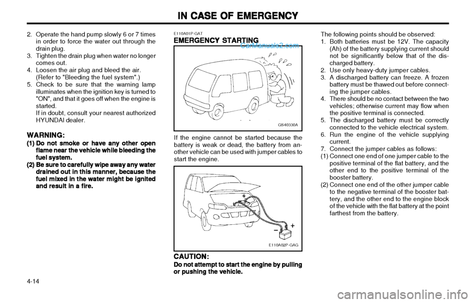
4-14 The following points should be observed:
1. Both batteries must be 12V. The capacity
(Ah) of the battery supplying current should not be significantly below that of the dis-charged battery.
2. Use only heavy-duty jumper cables.
3. A discharged battery can freeze. A frozen battery must be thawed out before connect- ing the jumper cables.
4. There should be no contact between the two vehicles; otherwise current may flow whenthe positive terminal is connected.
5. The discharged battery must be correctly connected to the vehicle electrical system.
6. Run the engine of the vehicle supplying current.
7. Connect the jumper cables as follows:
(1) Connect one end of one jumper cable to the positive terminal of the flat battery, and the other end to the positive terminal of thebooster battery.
(2) Connect one end of the other jumper cable to the negative terminal of the booster bat-tery, and the other end to the engine blockof the vehicle with the flat battery at the pointfarthest from the battery.
GS40330A
E110A02P-GAG
If the engine cannot be started because the battery is weak or dead, the battery from an-other vehicle can be used with jumper cables tostart the engine.
E110A01P-GAT
EMERGENCY STARTING
EMERGENCY STARTING EMERGENCY STARTING
EMERGENCY STARTING
EMERGENCY STARTING
CAUTION:
CAUTION: CAUTION:
CAUTION:
CAUTION:
Do not attempt to start the engine by pulling
Do not attempt to start the engine by pulling Do not attempt to start the engine by pulling
Do not attempt to start the engine by pulling
Do not attempt to start the engine by pulling
or pushing the vehicle.
or pushing the vehicle. or pushing the vehicle.
or pushing the vehicle.
or pushing the vehicle.
2. Operate the hand pump slowly 6 or 7 times
in order to force the water out through thedrain plug.
3. Tighten the drain plug when water no longer comes out.
4. Loosen the air plug and bleed the air. (Refer to "Bleeding the fuel system".)
5. Check to be sure that the warning lamp illuminates when the ignition key is turned to"ON", and that it goes off when the engine isstarted.If in doubt, consult your nearest authorizedHYUNDAI dealer.
WARNING:
WARNING: WARNING:
WARNING:
WARNING:
(1)(1)
(1)(1)
(1) Do not smoke or have any other open
Do not smoke or have any other open Do not smoke or have any other open
Do not smoke or have any other open
Do not smoke or have any other open
flame near the vehicle while bleeding the
flame near the vehicle while bleeding the flame near the vehicle while bleeding the
flame near the vehicle while bleeding the
flame near the vehicle while bleeding the
fuel system.
fuel system. fuel system.
fuel system.
fuel system.
(2)(2)
(2)(2)
(2) Be sure to carefully wipe away any water
Be sure to carefully wipe away any water Be sure to carefully wipe away any water
Be sure to carefully wipe away any water
Be sure to carefully wipe away any water
drained out in this manner, because the
drained out in this manner, because the drained out in this manner, because the
drained out in this manner, because the
drained out in this manner, because the
fuel mixed in the water might be ignited
fuel mixed in the water might be ignited fuel mixed in the water might be ignited
fuel mixed in the water might be ignited
fuel mixed in the water might be ignited
and result in a fire.
and result in a fire. and result in a fire.
and result in a fire.
and result in a fire.
Page 133 of 173

IN CASE OF EMERGENCY
IN CASE OF EMERGENCY IN CASE OF EMERGENCY
IN CASE OF EMERGENCY
IN CASE OF EMERGENCY
4-18 E130D01P-GAT
Front combination lamps
Front combination lamps Front combination lamps
Front combination lamps
Front combination lamps
Remove the bezel attaching screw from the front combination lamp. Then turn the bulb socket counterclockwise to remove it. To remove the bulb of the side turn-signal lamps, turn the bulb counterclockwise whilepressing it inward.
E130A01P-1
Truck
Minbus/Van
E130C01P-1
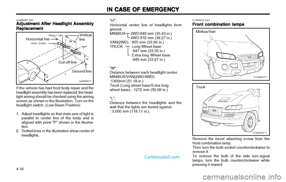
"H"; Horizontal center line of headlights from ground.
MINIBUS 2
WD:849 mm (33.43 in.)
4WD:972 mm (38.27 in.)
VAN(2WD) : 855 mm (33.66 in.)
TRUCK Long Wheel base
:847 mm (33.35 in.) Extra long Wheel base:845 mm (33.27 in.)
"W"; Distance between each headlight center. MINIBUS/VAN(2WD/4WD):1300mm (51.18 in.)Truck (Long wheel base/Extra longwheel base) : 1272 mm (50.08 in.) "L"; Distance between the headlights and the wall that the lights are tested against : 3,000 mm (118.11 in.).
If the vehicle has had front body repair and the
headlight assembly has been replaced, the head- light aiming should be checked using the aimingscreen as shown in the illustration. Turn on theheadlight switch. (Low Beam Position)
1. Adjust headlights so that main axis of light is parallel to center line of the body and is aligned with point "P" shown in the illustra-tion.
2. Dotted lines in the illustration show center of headlights.
G290B02P-AAT
Adjustment After Headlight Assembly
Adjustment After Headlight Assembly Adjustment After Headlight Assembly
Adjustment After Headlight Assembly
Adjustment After Headlight Assembly
Replacement
Replacement Replacement
Replacement
Replacement
G290B01Y
Vertical line
Cut-off line Ground line
Horizontal line
LW
H
H "P"
15mm (0.59in.)30mm(1.18in.)
Page 134 of 173

IN CASE OF EMERGENCY
IN CASE OF EMERGENCY IN CASE OF EMERGENCY
IN CASE OF EMERGENCY
IN CASE OF EMERGENCY
4-19
GS40460A
E130H01P-GAT
Step lamp (If installed)
Step lamp (If installed) Step lamp (If installed)
Step lamp (If installed)
Step lamp (If installed)
Remove the lens mounting screws, remove the
lens, and then remove the bulb by turning it counterclockwise while pressing it inward.
GS40430A
E130F01P-GAT
Licence-plate lamps
Licence-plate lamps Licence-plate lamps
Licence-plate lamps
Licence-plate lamps
Remove the lens mounting screws, remove the
lens, then remove the bulb by turning it counter- clockwise while pressing it inward. E130G01P-GAT
Room lamp
Room lamp Room lamp
Room lamp
Room lamp
Insert a screwdriver into the notch of the lamp
assembly and pry gently to remove the lens.
Remove the lamp bulb from the lamp holder.
NOTE:
NOTE: NOTE:
NOTE:
NOTE:
Wrap a piece of cloth around the tip of the
Wrap a piece of cloth around the tip of the Wrap a piece of cloth around the tip of the
Wrap a piece of cloth around the tip of the
Wrap a piece of cloth around the tip of the screwdriver in order to avoid scratching the
screwdriver in order to avoid scratching the screwdriver in order to avoid scratching the
screwdriver in order to avoid scratching the
screwdriver in order to avoid scratching the
lens.
lens. lens.
lens.
lens.
E130E01P-GAT
Rear combination lamps
Rear combination lamps Rear combination lamps
Rear combination lamps
Rear combination lamps
E130B01P-1
To remove the bulb of the position lamps, pull
out the bulb from the socket.
E130D01P-1
Truck Minbus/Van
Truck
Minbus/VanE130F01P
Remove the bezel attaching screws from the
rear combination lamp.
Then, turn the bulb socket counterclockwise to
remove it. And remove the bulb by turning it counterclock-
wise while pressing it inward.
Page 155 of 173

CONSUMER INFORMATION
CONSUMER INFORMATION CONSUMER INFORMATION
CONSUMER INFORMATION
CONSUMER INFORMATION
8-6 I040A01P-GAT
Vehicle Interior
Vehicle Interior Vehicle Interior
Vehicle Interior
Vehicle Interior
The following should be checked each time when the vehicle is driven:
o Light operation
o Windshield wiper operation
o Horn operation
o Defroster, heater operation (and air condi- tioning, if equipped)
o Steering operation and condition
o Mirror condition and operation
o Turn signal operation
o Accelerator pedal operation
o Brake operation, including parking brake
o Manual transmission operation, including clutch operation
o Automatic transmission operation, including "Park" mechanism operation
o Seat control condition and operation
o Seat belt condition and operation
o Sunvisor operation
If you notice anything that does not operate correctly or appear to be functioning correctly,inspect it carefully and seek assistance fromyour Hyundai dealer if service is needed. Adequate care of your vehicle at regular inter- vals serves to preserve the value and appear-ance as long as possible. Some maintenance items can be carried out bythe owner (Consumer Information), while othershould be done only by an authorized dealer(Periodic Inspection and Maintenance). Thissection describes only those items which canbe carried out by the owner. In the event amalfunction or other problem is discovered,have it corrected by an authorized HYUNDAIdealer. This section contains information oninspection maintenance procedures that youcan do yourself, if you so desire. Follow theinstructions and cautions for each of the vari-ous procedures. When checking or servicing the inside of the engine compartment, be sure the engine isstopped and has had a chance to cool down. Ifit is necessary to do work in the engine com-partment with the engine running, be especiallycareful that your clothing, hair, etc., becomesnot caught by the fan, V-belts, or other movingparts. I050A01P-GAT
Inspection items
Inspection items Inspection items
Inspection items
Inspection items
( 1 ) Engine oil
( 2 ) Engine coolant
(3) Battery
( 4 ) Brake fluid
( 5 ) Clutch fluid (hydraulic clutch only)
( 6 ) Washer fluid
( 7 ) Wheel condition (including spare wheel)
(8) Tire inflation pressure (including spare
wheel)
I020A02P-GAT
GENERAL CHECKS
GENERAL CHECKS GENERAL CHECKS
GENERAL CHECKS
GENERAL CHECKS
Engine Compartment
Engine Compartment Engine Compartment
Engine Compartment
Engine Compartment The following should be checked regularly:
o Engine oil level and condition
o Transmission fluid level and condition
o Brake fluid level
o Clutch fluid level
o Engine coolant level
o Windshield washer fluid level
o Accessory drive belt condition
o Coolant hose condition
o Fluid leaks (on or below components)
o Power steering fluid level and condition
o Tire pressure and condition (including spare)
o Battery condition I030A02P-GAT
Vehicle Exterior
Vehicle Exterior Vehicle Exterior
Vehicle Exterior
Vehicle Exterior The following should be checked monthly:
o Overall appearance and condition
o Wheel condition and wheel nut tightness
o Air cleaner filter condition
o Exhaust system condition
o Light condition and operation
o Windshield glass condition
o Wiper blade condition
o Paint condition and corrosion
o Fluid leaks
o Door and hood lock condition
Page 169 of 173

10-1
INDEX
INDEX INDEX
INDEX
INDEX
BRAKE SYSTEM ....................................................................... 3-13 ~ 3-14
BRAKE WARNING AND PARKING BRAKE INDICATION
LAMP-RED ................................................................................................ 2-9
C CARE OF CASSETTE TAPES ..............................................2-56 ~ 2-57
CARE OF DISC ...................................................................................... 2-56
CARRYING CHILDREN ........................................................................ 1-12
CENTRAL DOOR LOCKS .................................................................... 1-10
CHANGING GEARS ................................................................................. 3-5
CHARGE WARNING LAMP-RED ......................................................... 2-9
CHILD PROTECTION SLIDE DOOR ................................................1-12
CHILD RESTRAINT SYSTEM ................................................1-25 ~ 1-28
CIGARETTE LIGHTER ......................................................................... 2-23
CLUTCH FLUID ....................................................................................... 8-10
CLUTCH PEDAL FREE PLAY ............................................................ 8-14
D DAYTIME RUNNING LIGHTS ............................................................. 2-13
DEFROSTING/DEFOGGING ............................................................... 2-26
DIGITAL CLOCK ..................................................................................... 2-24
DISEL ENGINE ROOM ................................................................ 8 - 1 ~ 8 - 4
DIESEL PREHEAT INDICATION LIGHT-AMBER ..............2-9 ~ 2-10
DOOR-AJAR WARNING LAMP-RED .................................................. 2-9
DRINK HOLDER ..................................................................................... 2-22
DURING COLD WEATHER ....................................................3-16 ~ 3-17
E ECONOMICAL DRIVING ......................................................... 3-14 ~ 3-15
EMERGENCY STARTING ................................................................... 4-14
K000A01P-GAT
10.
10. 10.
10.
10.
INDEX
INDEX INDEX
INDEX
INDEX
A ADJUSTABLE FRONT SEATS ........................................................... 1-18
AIR CONDITIONER OPERATION .....................................................2-27
ANTENNA ................................................................................................. 2-58
ALTIMETER ................................................................................................. 2-7
ANTI-FREEZE ............................................................................................. 8-9
ANTI-LOCK BRAKE SYSTEM ............................................................ 3-12
ANTI-LOCK BRAKE WARNING LIGHT ...........................................2-10
APPEARANCE CARE .............................................................................. 5-1
ASHTRAY (Front) ................................................................................... 2-23
ASHTRAY (Rear) .................................................................................... 2-23
A/T OIL TEMPERATURE WARNING LIGHT ..................................2-10
AUDIO FAULT CODE ........................................................................... 2-55
AUXILIARY SEAT ................................................................................... 1-22
AUTOMATIC TRANSMISSION OPERATION ........................ 3 - 5 ~ 3 - 8
AUTOMATIC TRANSMISSION FLUID CHECK .............8-11 ~ 8-12
B BATTERY ..................................................................................................... 8-9
BEFORE OPERATION PRECAUTIONS FOR NEW VEHICLE .... 1-1
BI-LEVEL HEATING ............................................................................... 2-25
BLEEDING THE FUEL SYSTEM ..........................................4-13 ~ 4-14
BRAKE FLUID ......................................................................................... 8-10
BRAKE PEDAL ........................................................................................ 3-11
BRAKE PEDAL FREE PLAY ............................................................... 8-14
1010
1010
10