Page 512 of 1139

Service Check Signal Circuit Method:
NOTE: Use this procedure when the PGM Tester
software does not match the yearlmodel vehicle you
are working on.
1. With the ignition switch OFF, connect the Honda
PGM Tester (A) to the 16P data link connector {DLC)(B) located under the dash on the driver's side of
the vehicle.
With the vehicle on the ground, set the front wheels
in the straight ahead driving position.
Short the SCS circuit to body ground using the
Honda PGM Tester.
Turn the ignition switch ON (ll). The EPS indicator
comes on for about 6 seconds. Within 4 seconds of
turning the switch ON, while the EPS indicator is on,
turn the steering wheel 45 degrees to the left from
the straight ahead driving position, and hold the
steering wheel in that position until the EPS
indicator goes off.
Within 4 seconds afterthe EPS indicator goes off,
return the steering wheel to the straight ahead
driving position and release the steering wheel.
The EPS indicator comes on again 4 seconds after
releasing the steering wheel,
Within 4 seconds after the EPS indicator comes on,
turn the steering wheel 45 degrees to the left again
and hold it in that position.
The EPS indicator goes off after 4 seconds.
4.
1.Within 4 seconds after the EPS indicator goes off,
return the steering wheel to the straight ahead
driving position again and release the steering
wheel. The EPS indicator blinks twice 4 seconds
after releasing the steering wheel, indicating that
the DTC was erased.
NOTE: If the EPS indicator does not blink twice, an
error was made in the procedure and the DTC was
not erased. Turn the ignition switch OFF, and
repeat the operation from step 3.
Turn the ignition switch OFF afterthe EPS indicator
blinks twice.
9. Disconnect the Honda PGM Tester from the DLC.
10. Perform the DTC code output operation, and be
sure that the code has been erased.
17-21
Page 516 of 1139

EPS Gontrol Unit Inputs and Outputs at Connestor C (20P1
EPS CONTROL UNIT CONNECTOR C (2OP)
Wire side of female terminals
TerminalnumbelWire colorTerminal sign{Terminel name}DescriplionMeasuremeniTerminalsConditions{lqnition switch ON {lll)Voltage
2PNKT/S GND(Torque sensor qround)Ground for the torque
ORNvccl(Voltaqe common 1Power source fortorque3-Groundtartthe enqrneBa$erv voltaqeOV
5YEUBEDVT6(Voltaqe torque 6)Detects torque sensorstonal5 GroundStartthe engine andturn the steerino wheelAbout
YEUBLU(Warninq lamp)Drives the EPS indicatorlidhr6 GroundEPS ONtnotcatol uTl-OVBanerv voltaqe
7BLUAVHTVSP(Vehicle speed pulseiDetects the vehicle speedinput signal for the speedsensor or the ECM (4 pulse/
Raise the vehicle off theground and spin theAlternatingvoltage aboutOV 5V OV-5V
BRNSCS{Servjco check siqnal)Detects service check8-GroundSCS not groundedBattery voltage
10YELIG1llqnition 1Power source for activating10-Groundon switch ON (ll)Batterv voltaqeon switch OFF11G RN//ELvcc2(Voltaqe common 2)Drives the torque sensor1'l-Groundtan the enoineAbout5Von switch OFF8LU/ORNVT3(Voltaoe toroue 3)Detects torque sensor13-GroundStartthe engine andtrrrn the steerino wheelAbout5-0 v
YEUBLKT/SIG(Torque sensor F/SDetects torque sensorsrgnal15-GroundStartthe engineMomentarily 5 V
1'lLT GRN/BI KPSWiPower steerino switch)Provides power steeringswitch sionall7-GroundStartthe engine andnrrn the steerino wheel0-12V
19BLUNEPDetects the engine pulse19-GroundStartthe engine, and let;t idte
20GRYDIAG-HCommunications withHonda PGNI Tester20-GroundPGM Tester not5V
17-25
Page 549 of 1139
EPS Components
Steering Gearbox Overhaul (cont'd)
'll. Check the slider guide for damage and cracks.Using vernier calipers to measure the thickness ofthe slider guide. lf the thickness is less than servicelimit, replace the slider guide,
f Z,-----:-r-.--------.t.t'E-r
I (fr--', -.----
/i Il il ( t t , ,)))
|i@r
25.3 mm{0.925 in.}
Remove and discard the stop ring {A)on the
cylinder by expanding it with snap ring pliers.
Remove and discard the lock screw {B}.
13. Install the new lock screw on the rack housing.
14. Installthe new stop ring in the groove (C)on thecylinder by expanding it with a snap ring pliers. Becareful not to scratch or damage the housing
surface with the stop ring edges.
25.3 mm{0.925 in.l
12
17-58
15. Apply multipurpose grease to the indicated part
{shaded part) of the outer surface of the rackhousing. Do not apply to the dents and grooves.
\
I
Page 567 of 1139
Wheel Runout Inspection
1.Raise the vehicle, and support it with safety stands
in the proper location (see page 1-5,.
Check for a bent or deformed wheel.
Set up the dial gauge as shown, and measure the
axial runout by turning the wheel.
Front and rear wheel axial runout:
Standard:
Aluminum wheel: 0-0.7 mm (0-0.03 in.)
Service limit: 2.0 mm {0.08 in.l
4. Reset the dial gaugetothe position shown, and
measure the radial runout.
Front and rear wheel radial runout:
Standard:
Aluminum wheel: 0 0.7 mm (0 0.03 io.)
Service limit: 1.5 mm {0.06 in.}
lf the wheel runout is not within the specification,
checkthe wheel bearing end play (see page 18-8),
and make sure the mating surfaces on the brake
disc and the inside of the wheel are clean.
lf the bearing end play is within the specification
but the wheel runout is more than the service limit.
replace the wheel.
18-9
Page 606 of 1139
Frequent inhalation of brake pad dust, regardless of
material composition, could be hazardous to your
Front Brake Pads Inspection and Replacement
. Avoid breathing dust particles.
. Never use an air hose or brush to clean brake
assemblies. Use an OSHA-approved vacuum
cleaner.
lnspection
1. Raise the front of the vehicle, and support it with
safety stands in the proper location {see page 1'8).
Remove the front wheels.
2. Check the thickness of the inner pad iA) and outer
pad {B). Do not include the thickness of the brake
pad backing plate.
Brake pad thickness:
Standard: 9.5 10.5 mm (0.37 0.41 in.l
Service limit: 1.6 mm (0.06 in.)
Inner pad:
Outer pad:
lf the brake Dad thickness is less than the service
limit, replace allthe pads as a set.
Replacement
1. Remove the bolt (A), and pivot the caliper (B) upout
of the way. Check the hose and pin boots for
damage and deterioration.
'..'
, .a
&
\
A
2. Remove the pad shim iA) andpads{B).
.^h v/
\ tJ I
v ."r------B
(cont'd)
19-11
Page 608 of 1139

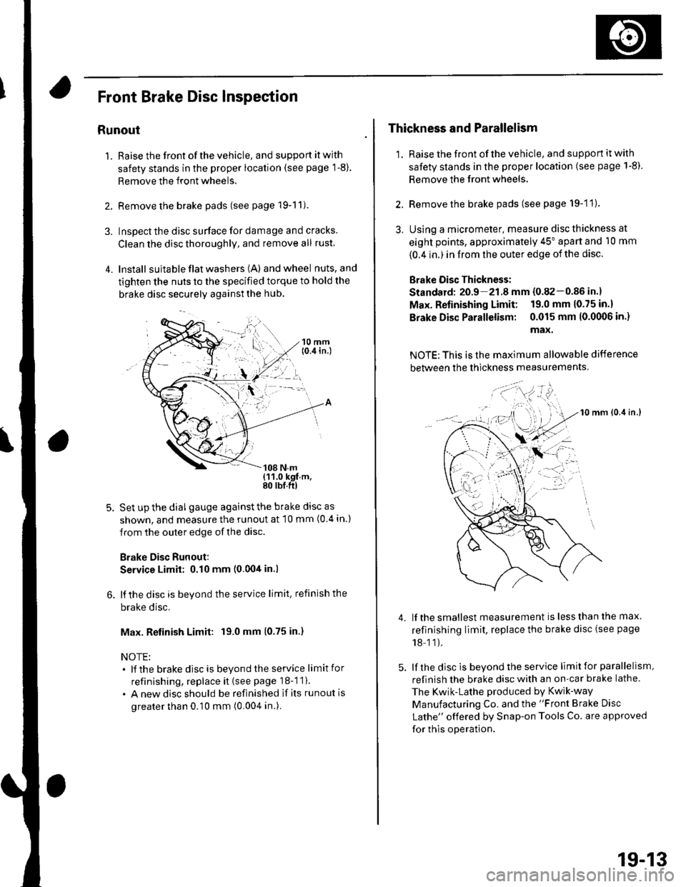
Front Brake Disc lnspection
Runout
1. Raise the front of the vehicle, and support it with
safety stands in the proper location (see page 1-8).
Remove the front wheels.
2. Remove the brake pads (see page 19-11).
3. Inspect the disc surface for damage and cracks.
Clean the disc thoroughly, and remove all rust
4. lnstall suita ble flat washers (A) andwheel nuts,and
tighten the nuts to the specified torque to hold the
brake disc securely against the hub.
Set up the dial gauge against the brake disc as
shown, and measure the runout at 10 mm (0 4 in.)
from the outer edge of the disc.
Brake Disc Runout:
Service Limit: 0.10 mm (0.00tt in.l
lf the disc is beyond the service limit, refinish the
brake disc.
Max. Retinish Limit: 19.0 mm (0.75 in.)
NOTE:. lf the brakedisc is beyondtheservice limitfor
refinishing, replace it (see page 18-1 1).
. A new disc should be refinished if its runout is
greater than 0.10 mm (0.004 in.).
Thickness and Parallelism
1. Raise the front of the vehicle, and support it with
safety stands in the proper location (see page 1-8).
Remove the front wheels.
2. Remove the brake pads (see page 19-11).
3. Using a micrometer, measure disc thickness at
eight points, approximately 45" apart and 10 mm
{0.4 in.) in from the outer edge of the disc.
Brake Oisc Thickness:
Standard: 20.9 21.8 mm {0.82-0.86 in.}
Max. Refinishing Limit: 19.0 mm 10.75 in.)
Brake Disc Parallelism: 0.015 mm 10.0(X)6 in.)
max.
NOTE: This is the maximum allowable difference
between the thickness measurements
10 mm lo.it in.l
lf the smallest measurement is less than the max.
refinishing limit, replace the brake disc (see page
18-11).
lf the disc is beyond the service limit for parallelism,
refinish the brake disc with an on-car brake lathe.
The Kwik-Lathe produced by Kwik-way
Manufacturing Co. and the "Front Brake Disc
Lathe" offered by Snap-on Tools Co. are approved
for this operation.
4.
': . --'t-'"'-
t,.
19-13
Page 615 of 1139

Conventional Brake Components
Rear Brake Pads Inspection and Replacement
Frequent inhalation of brake pad dust, regardless ofmaterial composition, could be hazardous to your
hea hh.. Avoid breathing dust particles.. Never use an air hose or brush to clean brake
assemblies, Use an OSHA-approved vacuum
cleaner.
Inspection
'1. Raise the rear of the vehicle, and support jt with
safety stands in the proper location (see page 1-8).Remove the rear wheels,
2. Check the thickness of the inner pad (A) andouterpad (B). Do not include the thickness of the brakepad backing plate.
Brake pad thickness:
Standard: 8.5 9.5 mm {0.33-0.37 in.}
Service limit: 1.6 mm (0.06 in.)
B -::--
lf the brake pad thickness is less than the servicelimit, replace allthe pads as a set.
3.
19-20
Replacement
1. Remove the bolt (A) and brake hose {B} from themounting bracket.
Remove the caliper bolts (C), and remove thecaliper (D) from the caliper bracket.
Remove the pad shims (A) and pads (B).3.
A
t{
\
tIA
A
\
r\
))
\
Page 617 of 1139

Conventional Brake Components
Rear Brake Disc Inspection
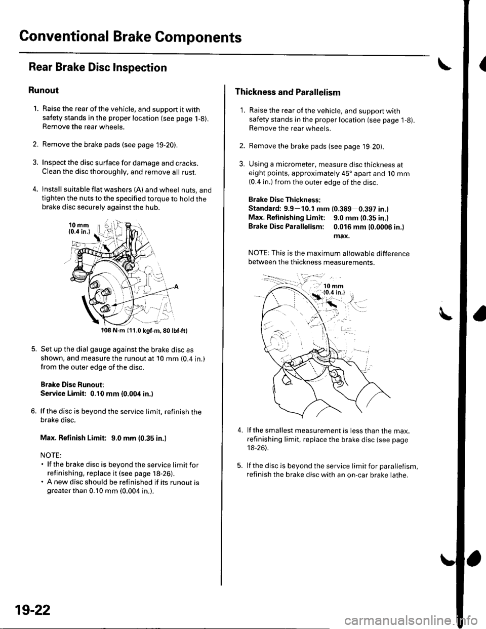
Runout
1. Raise the rear of the vehicle, and support it with
safety stands in the proper location (see page 1-8).Remove the rear wheels,
2. Remove the brake pads (see page 19-20).
3. Inspect the disc surface for damage and cracks.
Clean the disc thoroughly, and remove all rust,
4. lnstall suita ble f lat washers (A) and wheel nuts, andtighten the nuts to the specified torque to hold thebrake disc securely against the hub.
108 N.m (11.0 kgf.m,80lbf.ft)
Set up the dial gauge against the brake disc as
shown. and measure the runout at 10 mm (0.4 in.)
from the outer edge of the disc.
Brake Disc Runout;
Service Limit: 0.10 mm {0.004 in.)
lf the disc is beyond the service limit, refinish thebrake disc.
Max. Refinish Limit: 9.0 mm (0.35 in.)
NOTE:. lf the brake disc is beyondtheservice limitfor
refinishing, replace it (see page 18-26).. A new disc should be refinished if its runout isgreater than 0.10 mm (0.004 in.).
19-22
Thickness and Parallelism
1. Raise the rear of the vehicle, and support with
safety stands in the proper location (see page l-g).Remove the rear wheels.
2. Remove the brake pads {see page 19 20).
3, Using a micrometer, measure disc thickness ateight points, approximately 45'apart and 10 mm
{0.4 in.) from the outer edge of the disc.
Brake Disc Thickness:
Standard: 9.9-10.1 mm (0.389 0.397 in.l
Max. Retinishing Limit: 9.0 mm (0.35 in.)
Brake Disc Parallelism: 0.016 mm 10.0006 in.)
max.
4.lf the smallest measurement is less than the max.
refinishing limit, replace the brake disc (see page
18-26).
lf the disc is beyond the service limit for parallelism,
refinish the brake disc with an on-car brake lathe.