Page 238 of 1139
System Diagram
INTAKE
CMP SENSOR A
BRN/YELBLU/WHT
BLU/WHT
BLK/WHT
GRN/YEL
BLU/BLK
From No. ilACC {10A) fuse
VARIOUSSENSORS
CAMSHAFT -:-
BLK
It
Camshaft Position {CMP} Sensor
The CMP sensor detects camshaft angle position for the VTC system.
{cont'd}
11-31
:5i.T,""
Page 239 of 1139

Fuel and Emissions Systems
(
{
System Descriptions (cont'd)
ldle Control System
When the engine is cold, the Ay'C compressor is on, the
transmission is in gear, the brake pedal is pressed. thepower steering load is high, or the alternator is
charging, the ECIM controls current to the ldle Air
Control (lAC) valve to maintain the correct idle speed.
Refer to the System Diagram to see the functional
layout of the system.
Brake Pedal Position Switch
The brake pedal position switch signals the ECM when
the brake pedal is oressed.
Electrical Power Steering (EPS) Senser
The EPS sensor signals the ECM when the power
steering load is high.
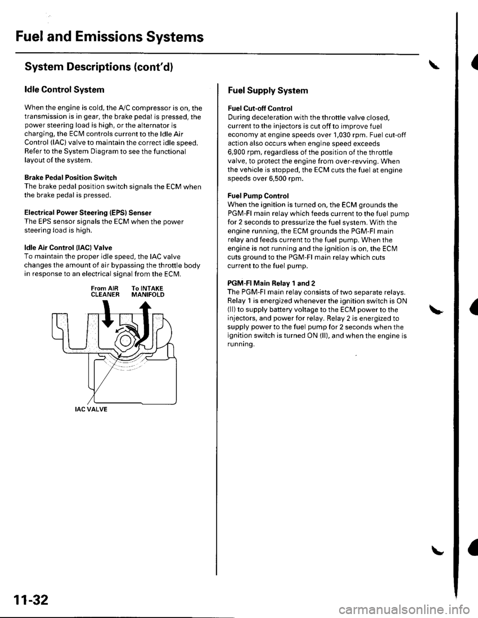
ldle Air Control llACl Valve
To maintain the proper idle speed, the IAC valve
changes the amount of air bypassing the throttle body
in response to an electrical signal from the ECM.
From AIR To INTAKECLEANER MANIFOLD
IAC VALVE
11-32
Fuel Supply System
Fuel Cut-off Control
During deceleration with the throttle valve closed,
current to the injectors is cut off to improve fuel
economy at engine speeds over 1,030 rpm. Fuel cut-off
action also occurs when engine speed exceeds
6,900 rpm, regardless of the position of the throttle
valve, to protect the engine from over-rewing. When
the vehicle is stopped. the ECM cuts the fuel at engine
speeds over 6,500 rpm.
Fuel Pump Control
When the ignition is turned on, the ECM grounds the
PGM-Fl main relay which feeds current to the fuel pump
for 2 seconds to pressurize the fuel system, With the
engine running. the ECM grounds the PGM-Fl main
relay and feeds current to the fuel pump. When the
engine is not running and the ignition is on, the ECI\4
cuts ground to the PGM-Fl main relay which cuts
current to the fuel pump.
PGM-FI Main Relay 1 and 2
The PGM-Fl main relay consists of two separate relays.
Relay 1 is energized whenever the ignition switch is ON(ll) to supply battery voltage to the ECM power to the
injectors, and power for relay, Relay 2 is energized to
supply power to the fuel pump for 2 seconds when the
ignition switch is turned ON (ll), and when the engine is
runnrng.
Page 242 of 1139

Evaporative Emission (EVAPI Control
System
Refer to the System Diagram to see the functional
layout of the system.
EVAP Canister
The EVAP canister temporarily stores fuel vapor from
the fuel tank until it can be purged back into the engine
and burned.
EVAP Canister Purge Valve
When the engine coolant temperatu re is below 149'F(65'C), the ECM turns off the EVAP canister purge valve
which cuts vacuum to the EVAP canister.
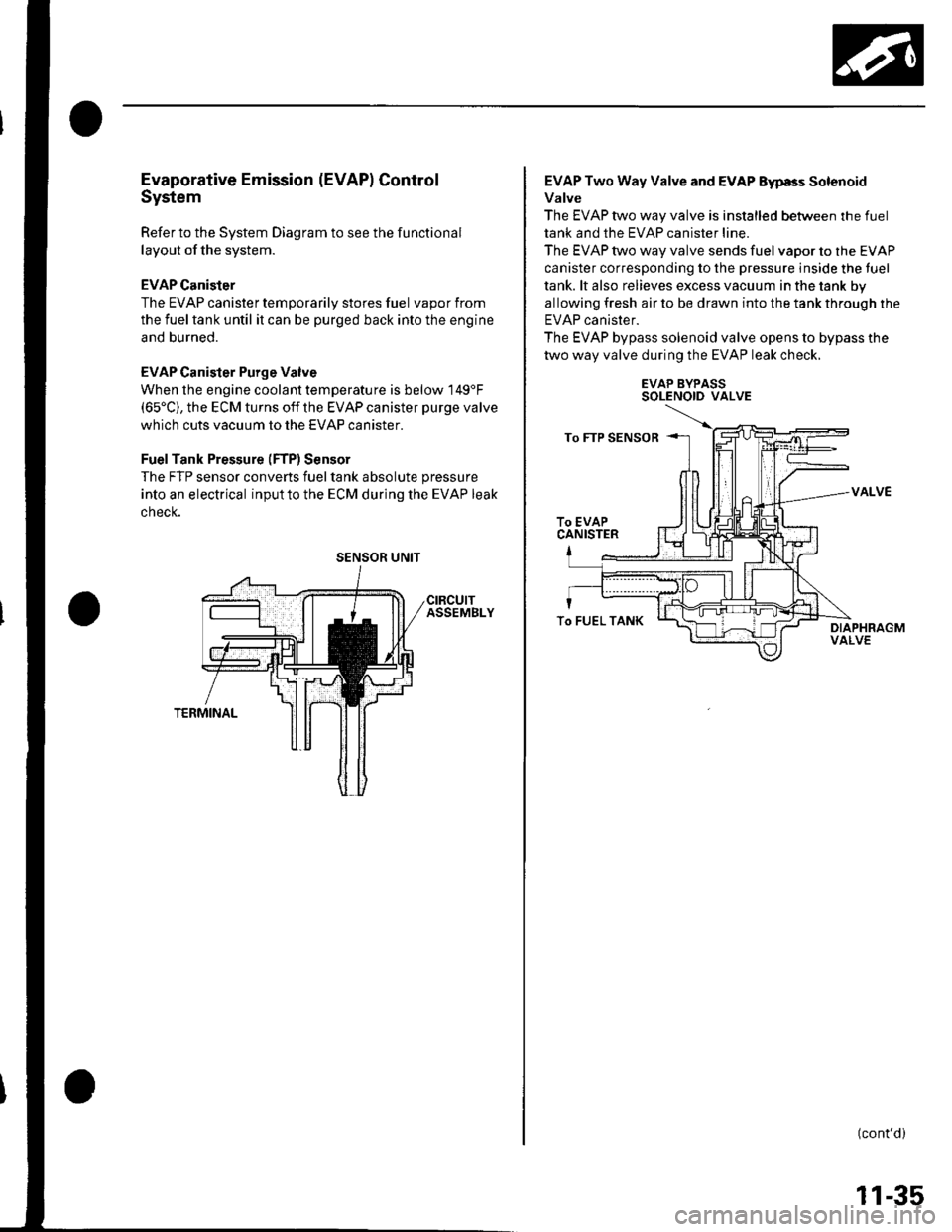
FuelTank Pressure (FTP) Sensor
The FTP sensor converts fueltank absolute pressure
into an electrical inputto the ECM during the EVAP leak
cnecK.
SENSOR UNIT
EVAP Two Way Valve and EVAP Eyp8s Solenoid
Valve
The EVAP two way valve is installed between the fuel
tank and the EVAP canister line.
The EVAP two way valve sends fuel vapor to the EVAP
canister corresponding to the pressure inside the tuel
tank. lt also relieves excess vacuum in the tank by
allowing fresh air to be drawn into the tank through the
EVAP canister.
The EVAP bypass solenoid valve opens to bypass the
two way valve during the EVAP leak check.
EVAP BYPASSSOLENOID VALVE
VALVE
(cont'd)
To FUEL TANK
11-35
Page 243 of 1139
Fuel and Emissions Systems
System Descriptions (cont'dl
ldle Control System Diagram
The idle speed of the engine is controlled by the ldle Air Control (lAC) varve:
'Aftertheenginestarts,theIACvalveopensforacertainamountoftime.Theamountofairisincreasedtoraisethe
idle sDeed.. When the engine coolant temperature is low, the IAC valve is opened to obtain the proper fast idle speed. Theamount of bypassed air is controlled in relation to engine coolant temperature.
INTAKE MANIFOLDIAC VALVEAKE AIR DUCT
CLEANER
\
BLK/REO
YEL/BLK ---< FromPGM.FIMAINRELAY
THROTTLE AODY
Intake Air System Diagram
This system supplies air for engine needs. A resonator in the intake air
drawn into the svstem.
VARIOUSSENSOnS
pipe provides additional silencing as air is
THROTTLE AODYVARIOUSSENSORS
BLK
BLK
I
11-36
{
Page 245 of 1139
Fuel and Emissions Systems
I
a
a
System Descriptions (cont'd)
ECM Circuit Diagram
CONNECTOi
mrrrrn
CMP SENSOR B(TDC SENSOn)
I-BRN/YEr-
11-38
\,
Page 247 of 1139
Fuel and Emissions Systems
System Descriptions (cont'dl
ECM Circuit Diagram {cont'd)
\
-{ffi]---1t-|
IATSENSOR
-{El------l
ECTSENSOS
T_""",,..
I-BFN/YEL
ft^--l
,","., J t-|':I REVERSEI LocKI soleloto+ vaLvE
t!j]]
CMPSENSOAA
L-IJUNCTIONI CONNECTOR
-
11-40
Page 253 of 1139

Fuel and Emissions Systems
How to Set Readiness Codes
Malfunction lndicator Lamp (MlL) Indication
(ln relation to Readiness Codesl
The vehicle has certain "readiness codes" that are part
of the on-board diagnostics for the emissions systems.
lf the vehicle's battery has been disconnected or gone
dead, if the DTCS have been cleared, or if the ECM has
been reset, these codes are set to incomplete. In some
states, part of the emission testing is to make su re these
codes are set to complete. lf all of them are not set to
complete, the vehicle may fail the emission test, or the
test cannot be finished.
To check ifthe readiness codes are complete, turn the
ignition switch ON (ll), but do not start the engine. The
MIL will come on for 15 20 seconds. lf it then goes off,
the readiness codes are complete. lf it blinks several
times, one or more readiness codes are not complete.
To set readlness codes from incomplete to complete.
do the procedure for the appropriate code.
11-46
L
Catalytic Converter Monitor and Readiness
Code
NOTE:. Do not turn the ignition switch off during the
procedure.
. All readiness codes are cleared when the battery is
disconnected or when the ECM is cleared with the
OBD ll scan tool or Honda PG lvl Tester.. Low ambient temperatures or excessive slop-and-go
traffic may increase the drive time needed to switch
the readiness code from incomplete to complete.' The readiness code will not switch to com Dlete until
all the enable criteria are met.. lf a fault in the secondary HO2S system caused the
MIL to come on. the readiness code cannot be set to
comDlete until vou correct the fault.
Enable Criteria. ECT at 158"F (70'C) or higher.. Intake air temperature (lAT) at 20"F (-7'C) or higher.. Vehicle speed is steady, and vehicle speed sensor
(VSS) reads more then 25 mph (13km/h).
Procedure
1. Connect the scan tool to the vehicle's data link \
connector (DLCi, and bring up the tool's generic \"
OBD ll mode.
Start the engine.
Test-drive the vehicle under stop-and-go conditions
with short periods of steady cruise. After about
5 miles (3 km), the readiness code should switch
from incomplete to complete.
lf the readiness code is still set to incomplete, check
for a temporary DTC. lf there is no DTC, one or
more of the enable crlteria were probably not met;
2.
3.
Page 254 of 1139

Evaporative Emissions (EVAP) Control
System Monitor and Readiness code
NOTE:
All readiness code are cleared when the batterV is
disconnected or when the ECM is cleared with the
OBD ll scan tool or Honda PGM Tester.
The enable criteria must be repeated if the intake air
temperature (lAT) drops lower than 36'F (20"C) from
its value at engine $an up.
Enable Criteria
At engine start up, ECT and IAT are higher than 32'F(0"C) , but lower than 95'F (35"C).
At engine start up, the ECT and IAT are within 12'F(7'C) of each other.
Procedure
1. Connect the scan tool to the vehicle's data link
connector (DLC), and bring up the tool's generic
OBD ll mode.
2. Start the engine.
3. Test-drive the vehicle under stop-and-go conditions
with short periods of steady cruise. After about
2.5 miles (1.6 km), the readiness code should
switch f rom incomplete to complete.
4. lf the readinesscode isstill setto incomplete, check
for a temporary DTC. lf there is no DTC, one or
more of the enable criteria were probably not met;
repeat the procedure.
Air Fuel Ratio (A/Fl Sensor Monitor and
Readiness Code
NOTE:. Do not turn the ignition switch off during the
orocedure.. All readiness codes are cleared when the baftery is
disconnected or when the ECM is cleared with the
OBD ll scan tool or Honda PGM Tester.
Enable Criteria
ECT at 140'F (60"C) or higher.
Procedure
1. Connect the scan toolto the vehicle's data link
connector (DLC), and bring up the tool's generic
OBD ll mode.
2. Start the engine.
3. Test-drive the vehicle under stop-and-go conditions
with short periods of steady cruise. During the
drive, decelerate (wirh the throttle fully closed) for
5 seconds. After about 3.5 miles (2.2 km). the
readiness code should switch from incomDlete to
complete.
4. lfthereadinesscodeisstill set to incomplete, check
for a temporary DTC. lfthere is no DTC, the enable
criteria was probably not meU repeat the procedure.
Air/Fuel Ratio (A/Fl Sensor Heater Monitor
Readiness Code
NOTE; All readiness codes are cleared when the battery
is disconnected or when the ECM is cleared with the
OBD ll scan tool or Honda PGM Tester,
Procedure'1. Connect the scan tool to the vehicle's data link
connector {DLC), and bring up the tool's generic
OBD ll mode.
2. Start the engine, and let it idle for 1 minute. The
readiness code should switch from incomplete to
comDlete.
3. lf the readiness code is still set to incomplete, check
for a temporary DTC. lf there is no DTC, repeat theproceoure.
(cont'd)
11-47