2003 HONDA CIVIC Brake line
[x] Cancel search: Brake linePage 651 of 1139

ABS Modulator-Control Unit Removal and lnstallation
NOTE:. Donotspill brake fluid on the vehicle; it may damage the painU if brakefluidgetsonthepaint,washitoff
immediately with water.. Becareful not to damage or deform the brake lines during removal and installation.. To prevent the brake fluid from flowing, plug and cover the hose ends and joints with a shop towel orequivalent
malenal.
Removal
'1. Turn the ignition switch OFF.
2. Pull upthelock(A) oftheABScontrol unit3lPconnector(B),thendisconnecttheconnector.
FLARE NUTl5 N.m (1.5 kgt.m,11 lbt.ftl
6)o
CII mm NUT8.8 N.m {0.9 kgl m.6.5lbf ft)
6 mm BOLT9.8 N.m11.0 ksf.m,7.2lbf.ft)
\.
--/Q \,
\---'
(cont'd)
19-57
Page 652 of 1139

ABS Gomponents
ABS Modulator-Control Unit Removal and Installation {cont'dl
3. Disconnectthe six brake lines.
4. Remove the two I mm nuts.
5. Remove the ABS modulator-control unit (C).
Installation
'1. InstalltheABS modulatorcontrol unit, then tighten the two 8 mm nuts.
2. Align the connecting surface ofthe ABS control unit 3'lP connector.
3. PushinthelockoftheABScontrol unit 31P connector until you hear it click into place. then connect the connector.
4. Connect the six brake Iines.
5. Bleed the brake system, starting with the front wheels.
6. Connect the PGM Tester, and do the solenoid function test for each wheel.
7. Bleed the brake system again, staning with the front wheels.
8. Start the engine, and check that the ABS indicator and brake system indicator go off.
9. Disconnect the Honda PGM Tester. Test-drive the vehicle, and check that the ABS indicator and brake qvqtem
indicator do not come on.
19-58
Page 679 of 1139

Rear Window Replacement
NOTE:. Put on gloves to protect your hands.. Wear eye protection while cutting the glass adhesive
with piano wire.. Use seat covers to avoid damaging any surfaces.. Do not damage the rear window defogger grid lines
and terminals.
1.Remove these items:
. Hatch lower trim panel (see page 20-53). Hatch spoiler (see page 20-99)
Remove these items:
. High mount brake light {see page 22-821. Rear window wiper motor {see page 22-1461
Disconnect the rear window defogger connectors
(A).
4.lf the old rear window is to be reinstalled, make
alignment marks across the glass and body with a
grease pencrl,
Apply protective tape along the inside and outside
edges of the hatch. Using an awl, make a hole
through the adhesive from inside the vehicle at the
corner portion of the rearwindow. Push the piano
wire through the hole, and wrap each end around a
piece of wood,
6. With a helper on the outside, pull the piano wire (A)
back and Jorth in a sawing motion. Hold the piano
wire as close to the rear window (B) as possible to
prevent damage to the hatch, and carefully cut
through the adhesive {C} around the entire rear
Cutting positions:
7. Carefully remove the rear window.
(cont'd)
20-25
Page 814 of 1139

Heater Unit/Core Replacement
SRS components are located in this area. Review the
SRS component locations (see page 23'13), and
precautions and procedures (see page 23-14) in the SRS
section before performing repairs or service.
1. Make sure you have the anti-theft code forthe radio,
then write down the freouencies for the radio's
Dreset buttons.
4.
Disconnect the negative cable from the battery,
Disconnect the suction and receiver lines from the
evaporator core (see page 21-42).
From under the hood, open the cable clamp (A),
then disconnect the heater valve cable (B) from the
heater valve arm (C). Turn the heater valve arm to
the fully opened position as shown
When the engine is cool, drain the engine coolant
from the radiator (see page 10-6).
6. Slide the hose clamps (A) back, the n d isconnect the
inlet heater hose (B) and the outlet heater hose (C)
from the heater core. Engine coolant will run out
when the hoses are disconnected; drain it into a
clean drip pan. Be sure not to let coolant spill on
the electrical parts or the painted surfaces. lf any
coolant spills, rinse it off immediately.
Remove the bolt and the heater valve, then remove
the mounting nut from the heater unit. Take care
not to damage or bend the fuel lines and the brake
lines, etc.
7.
8 x 1.25 mm12 N.m (1.2 kgf.m,8.7lbf.ft)
(cont'd)
21-43
Page 887 of 1139

Gauges
Self-diagnostic Procedure
The gauge assembly has a self-diagnosis function.. The Beeper Drive Circuit Check. The Indicator Drive Circuit ChecL. The LCD Segments Check. The Gauges Drive Circuit Check (Speedometer, Tachometer, Fuel gauge, Coolant temperature gauge). The Communication Line Check (the coolanttemperature signal line between the gauge and ECM)
NOTE: Indicators are also controlled via the communication line.
Entering the self-diagnosis f unction:
Before doing the self-diagnosis function, check the No. 9 (10A) fuse in the under-hood fuse/relay box and No. 10 {7.5A)fuse in the under'dash fuse/relay box.
1. Push and hold the trip/reset button.
2. Turn the lighting switch ON.
3. Turn the ignition switch ON (ll).
4. Within 5 sec., turn the lighting switch OFF, then ON and OFF again.5. Within 5 sec., release the trip/reset button, then push and release the button four times reDeatedlv.
NOTE:. While in the self-diagnosis mode, the dash lights brightness controller operates normally.'Whileintheself-diagnosismode,thetrip/resetbuttonisusedtostartthebeeperdrivecircuitcheckandthegauge
drive cicuit check.. lf the vehicle speed exceeds 1.2 mph 12 km/h) orthe ignition switch is tu rned OFF, the self,diag nosis mode ends.
oN flrl
lgnition
Switch
Lighting
Switch
Trip/Reset
Switch-> Move to selt-diagnosis mode.
5 sec.5 sec.
The Beeper Drive Circuit Check:
When entering the self-diagnosis mode, the beeper sounds five times
The Indicator Drive Circuit Check:
When entering the self-diagnosis mode, the following indicators blink.
Seat belt indicator, Door/hatch indicator, Brake system, Lowfuel indicator, Maintenance required indicator (USA),
Washer fluid level indicator (Canada), Oil pressure light.
v
OFF
22-56
Page 1133 of 1139

Service Manual lndex
)s
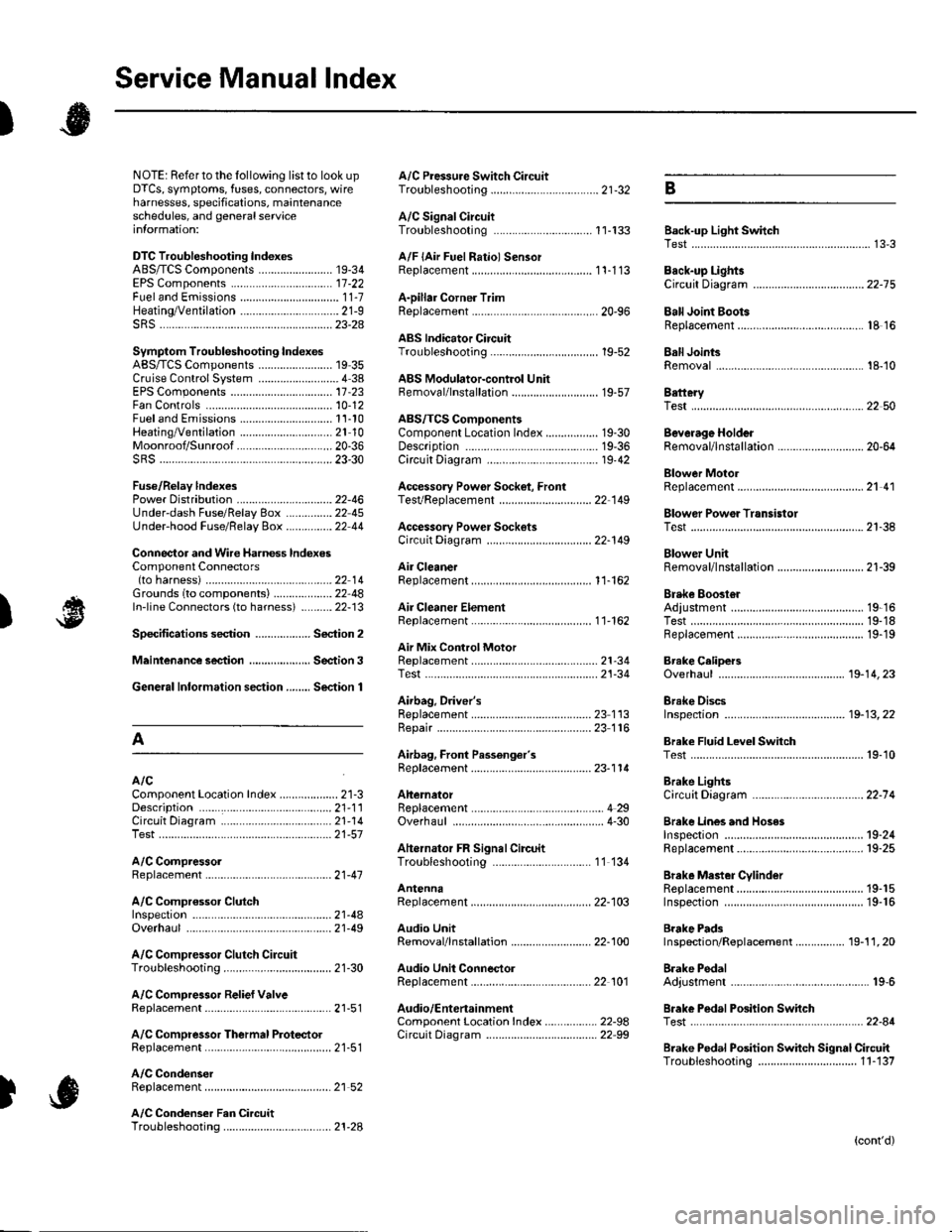
NOTE: Referto the lollowing listto look up A/C Pressure Switch CircuitDTCS, symptoms, fuses, connectors, wire Troubleshooting ......... ...-.-....-...-.-.-....-..21-32 Bharnesses, specifications, maintenanceschedules, and general serviceinlormation:
DTC Troubleshooting Indexes
A/C Signal CircuitTroubleshooting.........................-...... 11-'133 Back-up Light SwitchTest .......................................................... 13'3A/F lAir Fuel Ratiol SensorABS/TCS Components ........................ 19-34 Replacement ....................................... 1 1-113 Back-up Li9ht3EPS Components ................................. '17-22 Circuit DiagramFueland Emissions11-i A-Dillar Corner Trim
ABS Indicator Circuit
Heating/Ventilation ................................ 21-9 Replacement ...............-.....-..............-.... 20,96 Ball Joint BootssRS ........................................................ 23-28Replacement ......
... 19-52 Ball Joints
22-75
18 16
Remova1.............-.......... . ...........18-10Symptom Troubleshooting Indexes TroubleshootingABS/TCSComponents........................ 19 35Cruise Control System ..........................4 38 ABS Modulator-contml UnitEPS Components ................................. 17-23 Bemoval/lnstallation ............................ 19-57 BettervFan Controls10,12
Accessory Powor Socket Front
Blowor Pow€r Transistor
.......22 50
Blower UnitRemoval/lnstallation ............................ 21-39
Fuel and Em issions .............................. 11-10 ABS/TCS ComoonentsHeating/Ventilation..............................21 10 Component Location Index ................. 19-30 Beverage Holder
SRS ........................................................ 23'30 CircuitDiaqram.......................... 19'42Blower MotorReplacement .....21 41
21-38
Power 0istribution ...............................22-46 TesVReplacement .............................. 22'149Under-dash Fuse/Relay Box ............... 22 45Under-hood Fuse/Belay Box ...............22 44 Accessory Power Sockets
Fuse/Relay lndexes
(to harness)
Connector and Wire Harness lndexesComponent Connectors
Circuit Oiagram .................................. 22-149
Air Cleaner......2214 Rep1acemen1.....................................11-162
Air MixControl MotorMeintenence section .................... Section 3 Replacement ......................................... 21'34 Brake CelipersTest......................21-34 Overhaul19-14,23Gene.al lnlormation section........ Section 1
21.57
Airbag. Driver's
Ahernator FR Signal CircuitTroubleshooting .... .........-..........11 134
AntennaReplacement
Inspection ............................................. 19-24Rep|acement................. .................... 19-25
Bieke Meder Cylinder
Irake Discs
A
Replacement ....................................... 23 1 'l3 Inspection .................... ................... 19-13,22Repair ...........-...................................... 23 1 16Brake Fluid Level SwitchAirbag. Front Passenger's TestBeplacement....................................... 23-1 14AIC Brake LightsComponent Location fndex ...................21-3 Altemator CircuitDiagram....................................22-74Description.....................................-....21'1'l Beplacement ................ ........................... 4 29CircuitDiagram....................................21-14 Overhaul .................................................4-30 Brake Lines and Hoses
19.10
A/C CompressolReplacement .......-...-............................. 21 -41
A/C Compr€ssor ClulchRep1acement......................................... 19-15.........22-103 Inspection ............................................. 19-16Inspecton........Overhaul ..........
A/C CondenserReplacement,.,
21-442l-49 Audio Unit
Replacement
Brake PadsRemoval/lnstallation .. ........................22-100 Inspection/Rep1acement................ 19-11,20A/C Compressor Clutch CircuitTroubleshooting ................................... 21-30 Audio Unit Connector Brake Pedal22101 Adjustment..............19,6ArfC Comoressor Relief ValvcReplacement ..........-...-.......................... 21-51 Audio/Entertainment
A/C Compr$sor Thermal Protector Circuit DiagramReplacement............-............................ 21-51
Component Location In dex .................22-9A Test .......-.............. 22-84Breke Pedal Posilion Switch
Brake Pedal Position Switch Signal Clrcuit11-137
.....21 52
A/C Condenser Fan CircuitTroubleshooting ................... . . . . . .....21-28
)s
Troubleshooting
(cont'd)
Page 1136 of 1139

Service Manual Index
(cont'dl
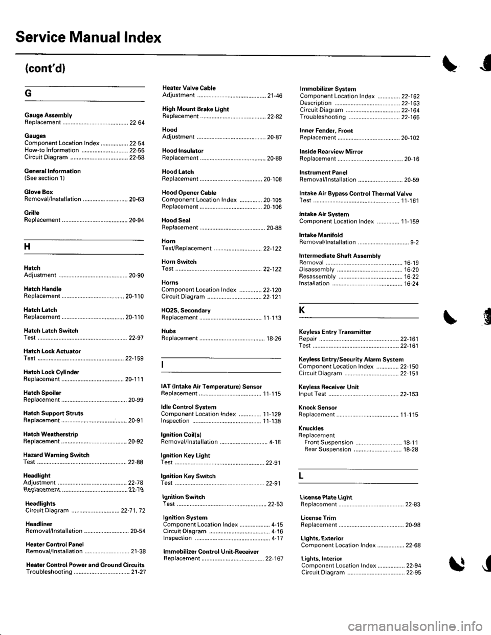
Gauge A3semblyReplacement......................................... 22 64
Gaug€sComponent Location Index ..........-...... 22 54How-to lnformation ........................22-56Circuit Diagram22-54
Heater Valve CableAdjustment ...................... .................... ?1-46
High Mount Brake Light8ep|acement......................................... 22 82
Hood
lmmobilizer SystemComponent Location In dex .............. 22-162
\
G
Description
Genoral Information(See seclion 1)
Glove BoxRemoval/1nsta11ation .......................-.... 20-63
GrilleReplacement...........-............................. 20-94
Hood lnsulatorReplacement......................................... 20-89
Hood LatchRep1acement................... ..........20 108
Hood Opener CableComponentLocation Index ..............20 105Replacement ................ . . ........... .....20 106
Hood SealBeplacement.-...........................-........... 20-88
HornTesVReplacement . . ................ ...... 22-122
CircuitDiagram ...........................22-164Troubleshooting ............................ 22,165
Inner Fender, FronlRepf acemenl....................................... 20-102
Inside Rearview MirrorReplacement..........-.............................. 20 16
Instrument PanelRemoval/1nsta11ation................. ....... 20-59
Intake Air Bypass ControlThermal ValveTesr................................ ..... ..11-161
Intake Air SystemComponent Location Index ...-.-........ 11-159
Intake ManitoldRemoval/1nsta11ation ................................ I 2
lntermediate Shaft AssemblyRemova1 ................-.-...-......................... 16-19Disassemb|y................... ... ......-.... 16,20Resassemb|y ........................................ 16 22Installation .........-...-.............................. 16-24
Keyless Entry Transmitter
Adjuslment
H
Adiustment .......
Hatch Handle
Horn SwitchTest ............-........
HornsComponent Location IndexCirc!it Diagram
H02S. SecondaryReplacement
..............22-120Replacement
22-122
22 12120-110
20-'110Hatch LatchReplacement$
K
Hatch Latch Switch
.... 11 113
HubsReplacement. ... .................................. 1A 26Test
Test
Replacement
Hatch Support StrutsBeplacement.....
Hatch WeatherstrioReplacement....
Hazard Warning Switchtest
ldle ControlSystemComponentLocation Index .............. 11-129Inspection,.,.........-.......,.,.,,,,,,.,,,.,.,..... 1'l 138
lgnition CoillslBemoval/lnstallation ...............-.............. 4 18
22-161Test ...................................................... 22 161
Keyless Entry/Security Alarm SystemComponenl Location Index .............. 22 150Circuil Diagram ................. . .............. 22 151
Keyless Receiver Unitlnput Test ............................................ 22-153
Knock SensorReplacement......-................................ 1 1 115
KnucklesReplacementFront Suspensron ............................. 18-1 1Rear Suspension ........ .................-... 18-28
Repair ...............
H.tch Lock Actuator22-159
Hatch Lock CylinderRep|acement....................................... 20,111
Hatch SpoilerIAT {lntake Air Temperature} SensorReplacement.,.........-...'11 115
20-91
20-92
.................... 22_88lgnition Key LightTest,,.,,,,.,...,......-.
H6adlightAdjustmentlgnition Key Switch
....................... 22-91
....................... 22-91..22-78TestReQ\ace$entlgnition SwitchTest .,,,.,.,.,,,,.,.,.......22-53License Plate LightReplacement...........-... - ... .....22-83
License TrimReplacement..................-...-..........-....... 20-98
Lights, ExteriorComponent Localion Index.................22 68
Lights,InteriorComponent Location Index................. 22-94CircuitDiagram .. .. ...... .... 22-95
HcadlightsCircuit Diagram .............................. 22-71, 72
HeadlinerRemoval/lnstallalion ............................ 20-54
Heater ControlPanelRemoval/1nsta11ation ............................ 21-38
Heater Control Power and Ground CircuitsTroubfeshooting......... .......................21-27
lgnition SystemComponent Location Index ................... 4-15CircuitDia9ram .................................... 4'161nspection ............................................... 4-17
lmmobilizer Control Unit-Receiver
J
22-161