2003 HONDA CIVIC Brake line
[x] Cancel search: Brake linePage 118 of 1139

Gylinder Head Removal
NOTE:. Use fender covers to avoid damaging painted
surfaces.
To avoid damage, unplug the wiring connectors
carefully whlle holding the connector portion.
To avoid damaging the cylinder head, wait until the
engine coolant temperature drops below 100'F (38"C)
betore loosening the cylinder head bolts.
Mark all wiring and hoses to avoid misconnection.
Also, be sure that they do not contact other wiring or
hoses, or interfere with other parts.
'1.
2.
3.
Drain the engine coolant (see page 10-6).
Remove the drive belt (see page 4-26).
Remove the intake manifold {see page 9-3).
Remove the air cleaner housing (see step 7 on page
5-2t.
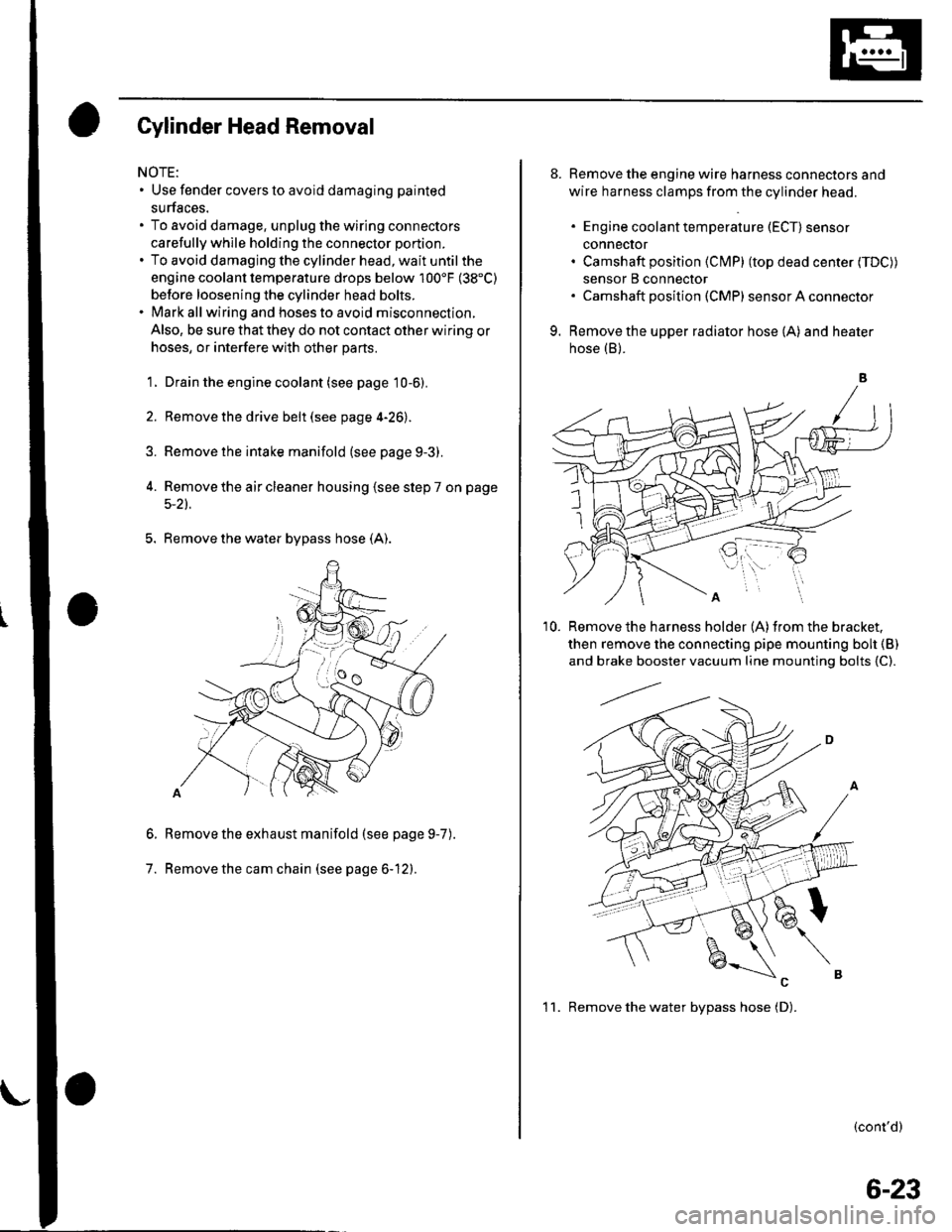
5. Remove the water bypass hose (A).
Remove the exhaust manifold (see page 9-7
Remove the cam chain (see page 6-12).
6.
7.
).
8. Remove the engine wire harness connectors and
wire harness clamps from the cylinder head.
. Engine coolant temperature (ECT) sensor
conneclor. Camshaft position (Cl\4P) (top dead center (TDC))
sensor B connector. Camshaft posilion (CMP) sensor A connector
9. Remove the upper radiator hose (A) and heater
hose (B).
'10. Remove the harness holder (A)from the bracket,
then remove the connecting pipe mounting boh {B)
and brake booster vacuum line mounting bolts {C).
(cont'd)
1 1. Remove the water bvpass hose (D).
6-23
Page 135 of 1139

Cylinder Head
8.
Cylinder Head lnstallation (cont'd)
7.Apply engine oil to the bolt threads and under thebolt heads of all the cylinder head bolts.
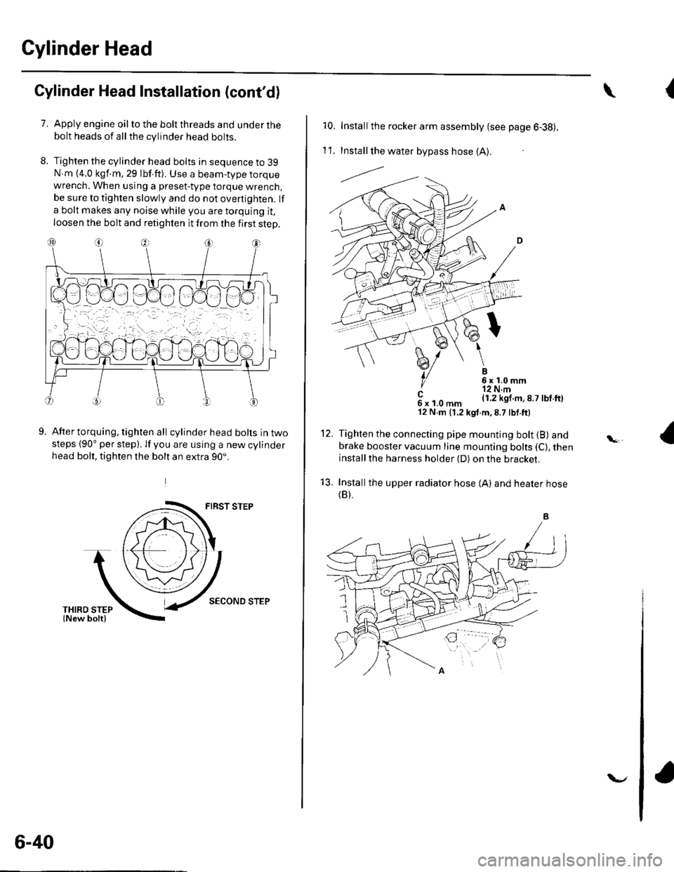
Tighten the cylinder head bolts in sequence to 39N.m {4.0 kgf.m, 29 lbf.ft). Use a beam-type torquewrench. When using a preset-type torque wrench,be sure to tighten slowly and do not overtighten. lf
a bolt makes any noise while you are torquing it,
loosen the bolt and retighten it from the first step.
9.After torquing, tighten all cylinder head bolts in twosteps (90" per step). lf you are using a new cylinderhead bolt, tighten the bolt an extra 90..
FIRST STEP
SECOND STEP
6-40
v
{\
10. Installthe rocker arm assembly {see page 6-38).
1't .Install the water bypass hose (A).
---l.-.
B6x1.0mm'r2 N.m(1.2 kgl.m,8.7 lbf.ftl
12.
't3.
c6xl.0mm'12 N,m (1.2 kgt.m,8.7 lbf.ft)
Tighten the connecting pipe mounting bolt (B) andbrake booster vacuum line mounting bolts (C), theninstallthe harness holder (D) on the bracket.
Installthe upper radiator hose {A) and heater hose(B).
Page 188 of 1139

lntake Manifold and Exhaust System
Intake Manifold Removal and Installation (cont'd)
9. lnstallthe air cleaner housing cover (A), and
connect the IAT sensor connector (B).
BC
Installthe breather hose (C).
lnstallthe EVAP canister hose (A), brake booster
vacuum hose (B), and vacuum hoses {C).
10.
11.
9-6
\
12. Installthe intake manifold cover.
6x1.0mm12 N.ml.1.2k91.m,8.7 tbf.ftl
Clean up any spilled engine coolant.
After installation, check that all tubes, hoses, and
connectors are installed correctly.
Inspect for fuel leaks. Turn the ignition switch ON
(ll) (do not operate the starter) so that the fuel pump
runs for about 2 seconds and pressurizes the fuel
line. Repeat this operation two or three times, then
check for fuel leakage at any point in the fuel line.
Refill the radiator with engine coolant, and bleed
air from the cooling system with the heater valve
open (see page 10-6).
to.
\-
Page 208 of 1139

Fuel and Emissions
Fuel and Emissions Systems
SpecialTools
General Troubleshooting
Information
DTC Troubleshooting lndex ....
Symptom Troubleshooting
1ndex...............
System Descriptions ................
Howto Set Readiness Codes ..
PGM-FlSystem
Component Location Index ....
DTC Troubleshooting ..............
MIL Circuit Troubleshooting ...
DLC Circuit Troubleshooting ..
Injector Replacement ...............
A,/F Sensor Replacement .........
Secondary HO2S
Replacement
ECT Sensor Reolacement .......
CMP Sensor B {TDC Sensor)
Replacement
IAT Sensor Replacement .........
Knock Sensor Replacement ....
CKP Sensor Reolacement .......
VTEC/VTC
Comoonent Location Index ....
DTC Troubleshooting ..............
VTC Oil Control Solenoid
Valve Removal/Test .............
CMP Sensor A Replacement ...
VTEC Solenoid Valve
Removal/lnsoection .............
ldle Control System
Component Location Index
DTC Troubleshooting ..............
A,/C Signal Circuit
TroubleshootinS ...................
Alternator FR Signal Circu it
TroubleshootinS ...................
EPS Signal Circuit
TroubleshootinS ...................
Brake Pedal Position Switch Signal
Circuit Troubleshooting .............
ldle Speed Inspection
ECM ldle learn Procedure .......
Fuel Supply System
Component Location Index
Fuel Pump Circuit Troubleshooting
1't-2
I I-J
11-7
1 1-10
11-12
11-46
11-49
11-52
11-97
11-109
11-111
11-113
11-113
11-114
11-114
11-115
11-115
11-116
11-117
1 1-1 18
11-127
11-128
11-128
11-129
1I-130
I t- t55
11-134
1 1- 135
1 1-137
1 1-138
1 1-139
1 1-140
11-141
11-144
Fuel PressureTest ................... 11-145
Fuel Lines Inspection ............... 11-146
Fuel Line/Ouick-Connect
Fittings Precautions ............. 1 1-148
Fuel Line/Ou ick-Con nect
Fittings Removal .................. 1 1-149
Fuel Line/Ou ick-Con nect
Fittings lnstallation ............... 11-150
Fuel Pressure Regu lator
Replacement ......................... 11-152
Fuel Fifter Replacement ........... 11-152
Fuel Pump/Fuel Gauge Sending
UnitReDlacement ................. 11-153
Fuel Pulsation Damoer
Rep1acement ......................... 11-154
Fuel Tank Reolacement ........... 11-155
Fuel GaugeSending UnitTest ....... 11-156
Low Fuel lndicatorTest ................. 1 1-158
Intake Air System
Comoonent Location Index .... 11-159
Throttle BodyTest ................... 11-160
Intake Air Bypass Control
Thermal Valve Test .............. 11-161
Air Cleaner Reolacement ........ 11-162
Air Cleaner Element
Reolacement ......................... 11-162
Throttle Cable Adjustment ...... 11-163
Th rottle Cable
Removal/lnstallation ............ 1 1-164
Th rottle Body Removal/
Installation .. 11-165
Th rottle Body Disassembly/
Reassemblv .......................... 11-166
Catalytic Converter System
DTC Troubleshooting .............. 1 1-167
PCV System
DTC Troubleshooting .............. 1 1-168
PCV Valve InsDection
and Test ...... 1 1- 169
PCV Valve Reolacement .......... 11-169
EVAP System
Component Location Index .... 11-170
DTCTroubleshooting .............. 11-171
EVAP Two Way Valve Test ...... 11-186
Fuel Tank Vaoor Control
Valve Test ... 11-187
EVAP Canister Replacement ... 11-189
Fuel Tank Vaoor Control
Valve Reolacement .............. 1 1-189Fuel Pressu re Relieving ...........
Page 230 of 1139

ECM Inputs and Outputs at Connector E (31P)
ltMoFPR
2$.c2s
i6SFIO2SHTC
1
IV RLY
IAFSHTCR
9tGl
14FTP15ELD
16EPSLD
t8202,4/BS21VSV
22BKSW23K LINE24SEFMJ26NEP
21lvoCD
29scs30WEN31MIL
Wire side of female terminals
NOTE: Standard battery voltage is 12 V.
TerminalWire colorTerminalnameDescriptionSignal
20BLU/RED2WBS (EVAPORATIVEEMISSION (EVAP)BYPASSSOLENOID VALVE)
Drives EVAP bypass With ignition switch ON (ll): baftery voltagesolenoid valve
21LT GRN/REDVSV (EVAPORATIVE
EI\4ISSION iEVAP)CANISTEB VENT SHUTVALVE)
Drives EVAP canister ventshut valveWith ignilion switch ON (ll): battery voltage
22WHT/BLKBKSW lBRAKE PEDALPOSITION SWITCH)Detects brake pedaloosition switch sionalWith brake pedal released: about 0 VWith hrake nedal nresse.l: batterv voltaoe23LT BLUK-LIN ESends and receives scanWith ignition switch ON (li)r pulses or battery
YELSEFMJCommunicates withmrltinleY eontrol unitWith ignition switch ON (ll): about 5 VWith enoine runnino under load: DUlses26BLUNEP (ENGINE SPEEDPULSE)Outputs engine speed pulseWith engine running: pulses
21RED/BLU \40CD fl\4MOBTLTZERCODE)Detects imrnobilizer signal
29BRNSCS (SERVICE CHECKSIGNAL)Oetects service check signalWith the service check signal shorted with the PGMTester: about 0 VWiih rhe service check sional ooened: about 5 V
30RED,A/VHTWEN (WRITE ENABLESIGNALiDetects write enable signal With ignition switch ON (ll): about 0 V
GRN/ORNMIL (MALFUNCTION
INDICATOR LAMP)Drives N4lLWith MIL turned ON: about 0 VWith MIL turned OFF: batterv voltaqe
(cont'd)
11-23
Page 402 of 1139

Clutch Master Cylinder Replacement
NOTE: Do not spill brake fluid on the vehicle; it may
damage the paint; if brake fluid does contact the paint,
wash it off immediatelV with water.
1. Pry out the lock pin (A), and pullthe pedal pin (B)
out of the yoke. Remove the master cylinder
mounting nuts (C).
Remove the air cleaner housing cover and the air
cleaner housing (see step 6 on page 5-2).
Remove the brake fluid from the clutch master
cylinder reservoir with a syringe.
Remove the clutch line bracket from the frame rail,
and remove the clutch line clip.
Remove the clutch master cylinder (A), and pull it
toward the middle of the engine compartment.
Remove the retaining clip (B). Disconnect the clutch
line (C). Plug the end of the clutch line with a shop
towelto prevent brake fluid from coming out.
g-E
3.
6. Disconnect the reservoir hose (D) fromtheclutch
master cylinder reservoir. Plug the end of the
reservoir hose with a shop towel to prevent brake
fluid from coming out.
7. Remove the O-ring (E) and the clutch master
cylinder seal (F) from the master cylinder.
8. Installthe clutch master cylinder in the reverse
order of removal. Install a new O-ring.
9. Make sure the hose clamps (A) are positioned on
the master cylinder (B) and reservoir (C) as shown.
(cont'd)
UP
i
12-5
Page 404 of 1139

Slave Cylinder Replacement
NOTE:. Use fender covers to avoid damaging painted
surfaces.. Do not spill brake fluid on the vehicle; it may damage
the paint; if brake fluid does contact the paint, wash it
off immediately with water.
1. Write down the frequencies for the radio's preset
buttons. Disconnect the negative ( ) cable first,
then the positive (+)cable from the battery.
Remove the battery.
2. Remove the battery tray.
a
Remove the air cleaner housing cover and the air
cleaner housing (see step 6 on page 5-2).
Remove the intake air duct (see step 8 on page 5-3) .
Remove the clutch line bracket (A).
4.
5.
6. Remove the mounting bolts (A) andtheslave
cylinder (B).
Remove the roll pins (C). Disconnect the clutch line(D), and remove the O-ring (E). Plug the end of the
clutch line with a shop towel to prevent brake fluid
f rom coming out.
Installthe slave cylinder in the reverse order of
removal. Install a new O-ring (A).
7.
,,6NJ'
=--#.q!4sEn(P/N 08798-90021
9.
(Brak6 Assembly Lube)
Pullthe boot (B) back, and apply brake assembly
lube to the boot and slave cylinder rod (C). Reinstall
the boot.
Apply super high temp urea grease (P/N 08798-
9002) to the push rod of the slave cylinder. Tighten
the slave cylinder mounting bolts to 22 N m (2.2
kgf m, 16lbf.ft).
(cont'd)
12-7
10.
Page 421 of 1139

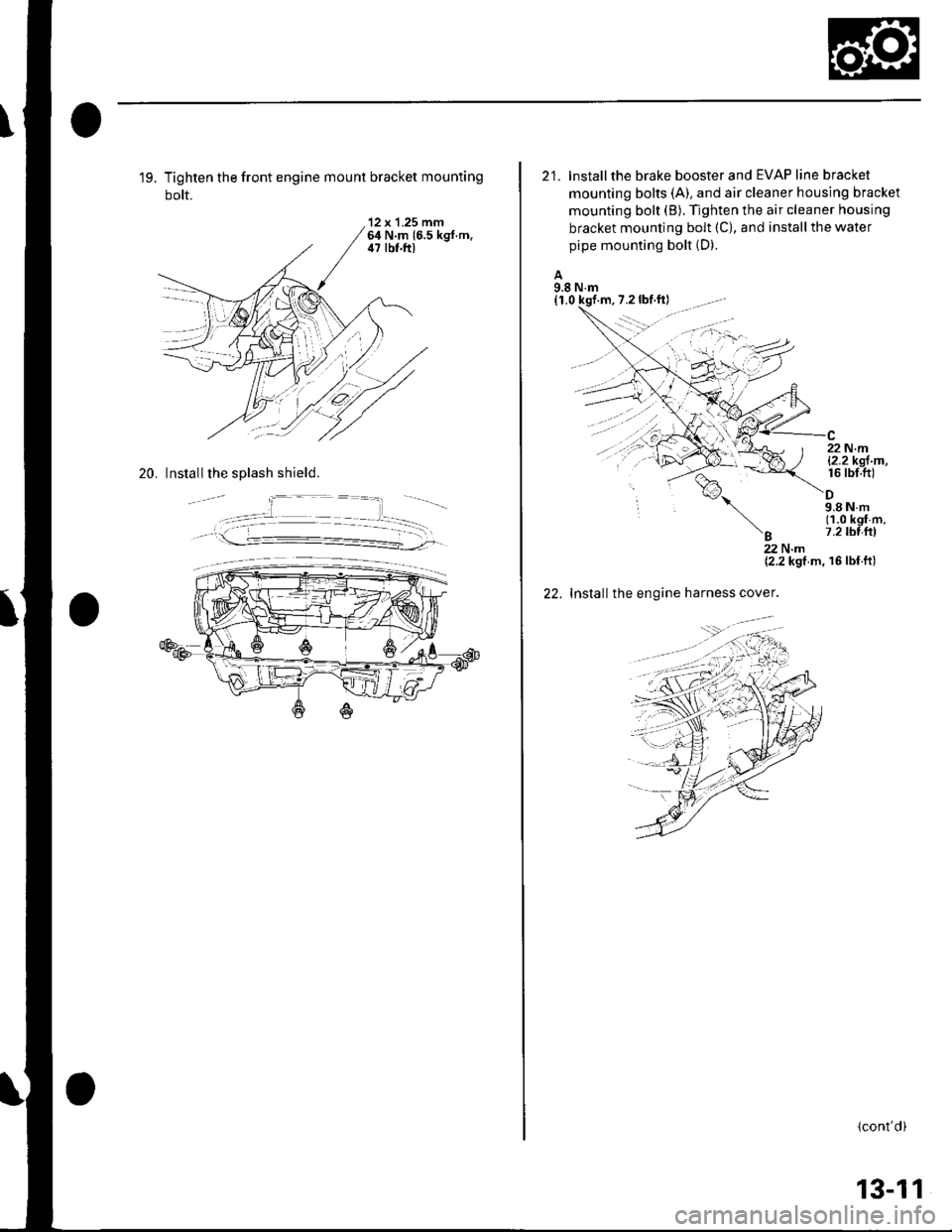
19. Tighten the front engine mount bracket mounting
bolt.
'12 x 1.25 mm64 N.m 16.5 kgf.m,il7 lbf.ft)
20. Install the splash shield.
21. lnstallthe brake booster and EVAP line bracket
mounting bolts (A). and air cleaner housing bracket
mounting bolt (B). Tighten the air cleaner housing
bracket mounting bolt (C), and install the water
pipe mounting bolt (D).
A9.8 N.m(1,0 kqf
%,
'B
22 N.ml2.2kgl m,16 rbt.ft)
9.8Nm(1.0 kgf m.7.2 tbl{rl
22.
22Nm{2.2 kgf m, 16 lbf ft)
Installthe engine harness cover.
(cont'd)
13-11