2003 HONDA CIVIC ERS
[x] Cancel search: ERSPage 1038 of 1139
ISystem Description
SRS Components
Airbags
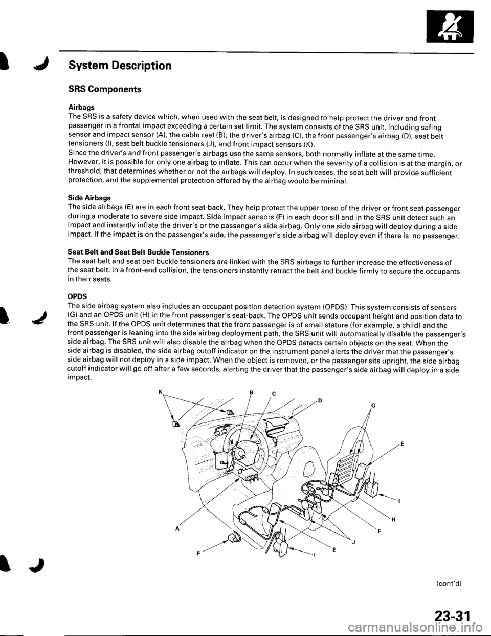
The SRS is a safety device which, when used with the seat belt, is designed to help protect the driver and frontpassenger in a frontal impact exceeding a certain set limit. The system consists ofthe SRS unit, including safingsensor and impact sensor (A), the cable reel (B), the driver's airbag (C), the front passenger,s airbag (D). seat belttensioners (l), seat belt buckle tensioners (J), and front impact sensors (K).
Since the driver's and front passenger's airbags use the same sensors, both normally inflate at the same ttme.However, it is possible for only one airbag to inflate. This can occur when the severity of a collision is at the margin, orthreshold, that determines whether or not the airbags will deploy. In such cases, the seat belt will provide sufficientprotection, and the supplemental protection offered by the airbag would be mininal.
Side Airbags
The side airbags (E) are in each front seat-back. They help protect the upper torso of the driver or front seat passenger
during a moderate to severe side impact. Side impact sensors (F) in each door sill and in the SRS unit detect such animpact and instantly inflate the driver's or the passenger's side airbag. Only one side airbag will deploy during a sideimpacl. lf the impact is on the passenger's side, the passenger's side airbag will deploy even if there is no passenger.
Seat Belt and Seat Belt Buckle Tensioners
The seat belt and seat belt buckle tensioners are linked with the SRS airbags to further increase the effectiveness ofthe seat belt. ln a front-end collision, the tensioners instantly retract the belt and buckle firmly to secure the occupantsin their seats.
OPDS
The side airbag system also includes an occupant position detection system (OpDS). This system consists of sensors(G)and an OPDS unit (H) in the front passenger's seat-back. The OPDS unit sends occupant heighl and position data tothe SRS unit. lf the OPDS unit determines that the front passenger is of small stature (for example, a child) and thefront passenger is leaning into the side airbag deployment path, the SRS unit will automatically disable the passenger'sside airbag. The SRS unit will also disable the airbag when the OPDS detects certain obiects on the seat. When theside airbag is disabled, the side airbag cutoff indicator on the instrument panel alerts the driver that the passenger'sside airbag will not deploy in a side impact. When the object is removed, or the passenger sits upright, the side airbagcutoff indicator will go off after a few seconds, alerting the driver that the passenger's side airbag will deploy in a sideimDact.
(cont'd)
I
23-31
Page 1039 of 1139
sRs
System Description (cont'dl
SRS Operation
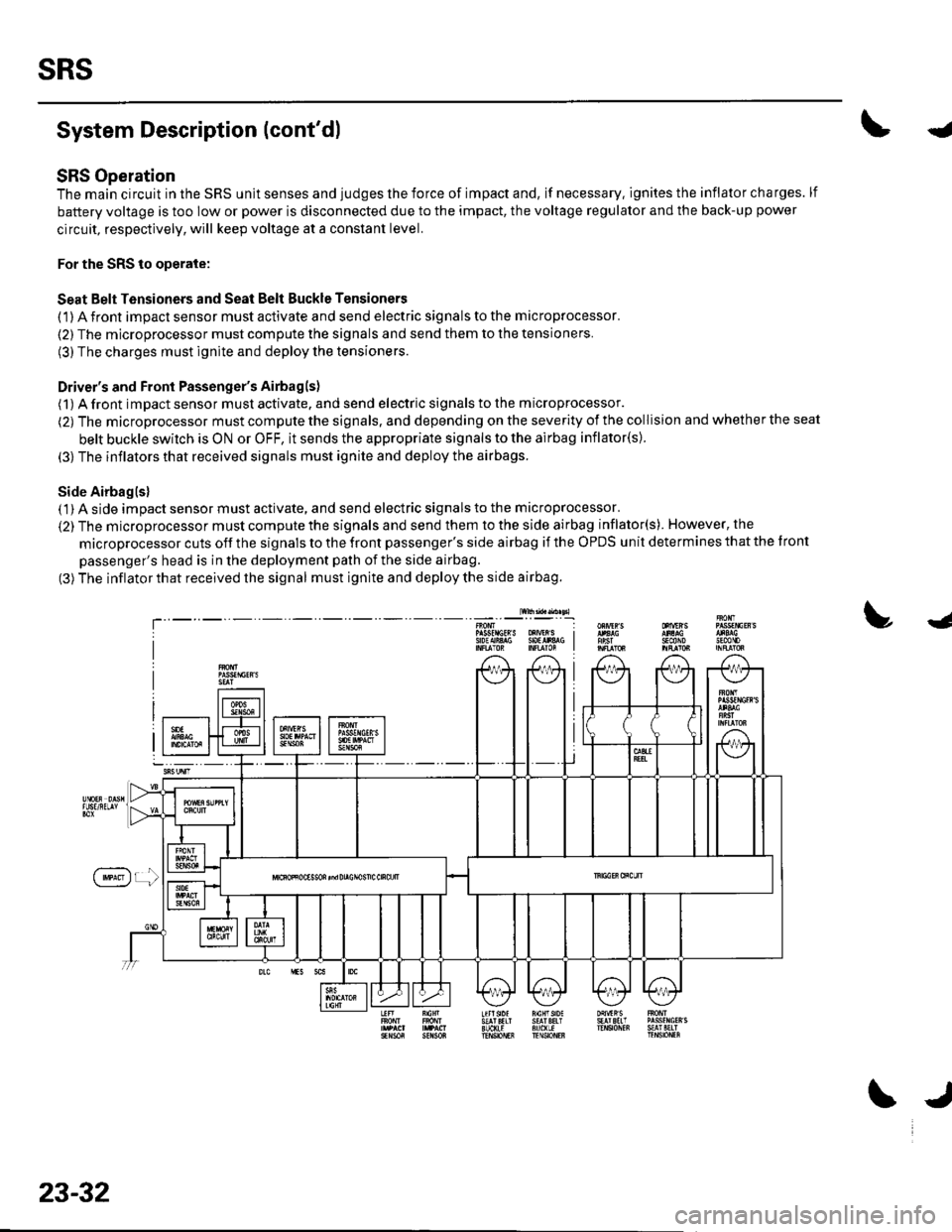
The main circuit in the SRS unit senses and judges the force of impact and, if necessary. ignites the inflator charges. lf
battery voltage is too low or power is disconnected due to the impact, the voltage regulator and the back-up power
circuit, respectively, will keep voltage at a constant level.
For the SRS to operate:
Seat Belt Tensioners and Seat Belt Buckle Tensioners
(1) A front impact sensor must activate and send electric signals to the microprocessor.
(2) The microprocessor must compute the signals and send them to the tensioners.
(3) The charges must ignite and deploy the tensioners.
Driver's and Front Passenger's Airbagls)
(1) A front impact sensor musl activate. and send electric signals to the microprocessor.
(2) The microprocessor must compute the signals. and depending on the severity of the collision and whether the seat
belt buckle swilch is ON or OFF, it sends the appropriate signals to the airbag inflator(s).
(3) The inflators that received signals must ignite and deploy the airbags.
Side Airbaglsl( 1) A side impact sensor must activate, and send electric signals to the microprocessor.
(2) The microprocessor must compute the signals and send them to the side airbag inflator(s). However, the
microprocessor cuts off the signals to the front passenger's side airbag if the OPDS unit determines that the tront
passenger's head is in the deployment path of the side airbag.
(3) The inflator that received the signal must ignite and deploy the side airbag.
lw$ad..n sl
!J
T'sEcttoJn0mP gsfrlctR S oXrVEr S I9oEAiA$ SOtlr&G I
f'**)r !
23-32
\J
Page 1043 of 1139
sRs
J
a
DTC Troubleshooting
DTC 1-1: Open in Driver's Airbag Inflator
DTC 1-2: Increased Resistance in Driver's
Airbag Inflator
Special Tools Required. SRS inflator simulator 07SAZ-TB4011A. SRS simulator lead F 07XAZ-S230100
1. Erase the DTC memory (see page 23-26).
2. Turn the ignition switch ON {ll), and check that the
SRS indicator comes on for aboul 6 seconds and
then goes off.
Does the SBS indicator stay on?
YES-Go to step 3.
NO Intermittent failure, system is OK at this time.
Go to Troubleshooting Intermittent Failures (see
page 23-26).
3. Turn the ignition switch OFF. Disconnect the
battery negative cable, and wait for 3 minutes.
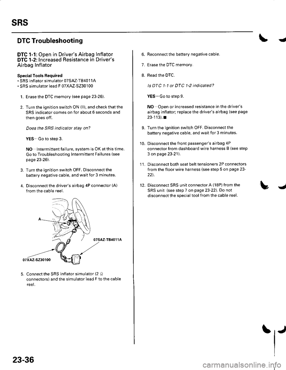
4. Disconnect the driver's airbag 4P connector (A)
from the cable reel.
07sAz-TB4011A
07xaz-s230100
5. Connect the SRS inflator simulator (2 Q
connectors) and the simulator lead F to the cable
reet.
23-36
6. Reconnect the battery negative cable.
7. Erase the DTC memory.
8. Read the DTC,
ls DTC 1-1 or DTC 1-2 indicated?
YES-Go to step 9.
NO Open or increased resistance in the driver's
airbag inflator; replace the driver's airbag (see page
23-113).t
9. Turn the ignition switch OFF. Disconnect the
battery negative cable, and wait ior 3 minutes.
10. Disconnect the front passenger's airbag 4P
connector from dashboard wire harness B (see step
3 on page 23-21).
1 1. Disconnect both seat belt tensioners 2P connectors
from the floor wire harness (see step 5 on page 23-
22t.
12. Disconnect SRS unit connector A (18P)from the
SRS unit (see step 7 on page 23-22). Do not
disconnect the special tool from the cable reel.
Page 1076 of 1139
I
DTC s-1, 5-2, 5-4, s-8, 6-3, 6-4,6-7,6-8,7-1,
7-2,7-3, A-1,4-2, 8-3, 8-4, 8-5, 8-6, 9-1, 9-2:
Internal Failure of the SRS Unit
NOTE: Before troubleshooting any of these DTCs, check
the battery/system voltage. lf the voltage is low, repair
the charging system or replace the battery before
troubleshooting the SRS. lf the battery/system voltage
is now OK, ask the customer if the battery ever went
oeao,
1. Erase the DTC memory (see page 23-26).
2. Turn the ignition switch ON (ll), and check that the
SRS indicator comes on for about 6 seconds and
then goes off.
Does the SRS indicatot stay on?
YES Replace the SRS unit (see page 23-122).1
NO Intermittent failure, system is OK at this time.
Go to Troubleshooting lntermittent Failures (see
page 23-26).
l
I
DTC 10-1, 10-2, 10-3, 10-4, 10-s, 10-6, 10-7:
Airbags, Side Airbags, and/or Seat Belt and
Seat Belt Buckle Tensioners Deployed
The SRS unit must be replaced after any airbags and/or
tensioners have deployed (see page 23-122). !
23-69
Page 1111 of 1139
sRs
DTG Troubleshooting (cont'dl
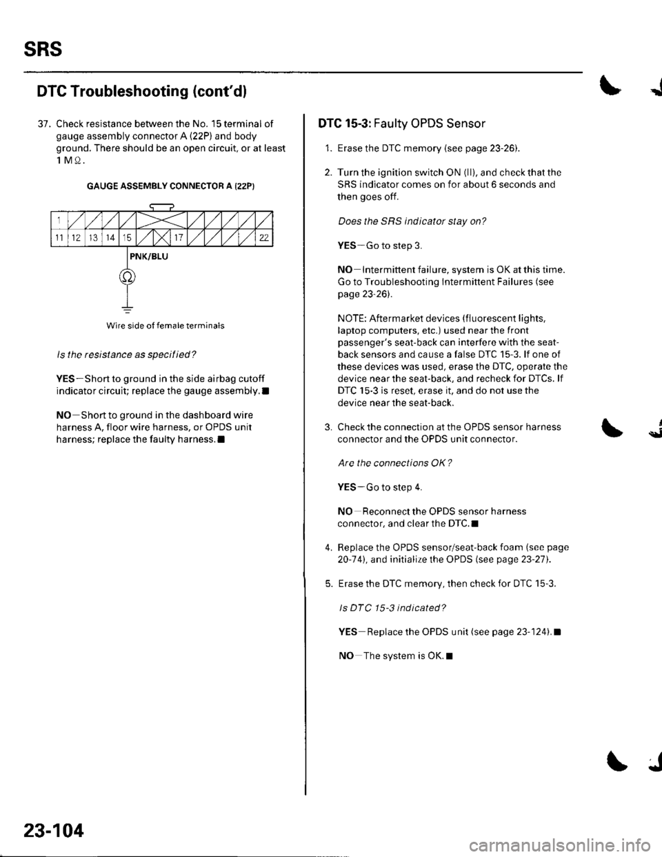
37. Check resistance between the No. 15 terminal of
gauge assembly connector A (22P) and body
ground. There should be an open circuit, or at least
1M0.
GAUGE ASSEMBLY CONNECTOR A I22PI
ls the resistance as specified?
YES-Short to ground in the side airbag cutoff
indicator circuit; replace the gauge assembly.l
NO Short to ground in the dashboard wire
harness A, floor wire harness, or OPDS unit
harness; replace the faulty harness.l
Wire side of female terminals
23-104
J
DTC 15-3: Faulty OPDS Sensor
1. Erase the DTC memory {see page 23-261.
2. Turn the ignition switch ON (ll), and check that the
SRS indicator comes on for about 6 seconds and
then goes off.
Does the SRS indicator stay on?
YES-Go to step 3.
NO Intermittent failure, system is OK at this time.
Go to Troubleshooting Intermittent Failures (see
page 23-26).
NOTE: Aftermarket devices (fluorescent lights,
laptop computers, etc.) used near the front
passenger's seat-back can interfere with the seat-
back sensors and cause a false DTC 15-3. lf one of
these devices was used, erase the DTC, operate the
device near the seat-back, and recheck for DTCs. lf
DTC 15-3 is reset, erase it, and do not use the
device near the seat-back.
3.
4.
Check the connection at the OPDS sensor harness
connector and the OPDS unit connector.
Are the connections OK?
YES-Go to step 4.
NO Reconnect the OPDS sensor harness
connector, and clear the DTC.I
Replace the OPDS sensor/seat-back foam (see page
20-141, and initialize the OPDS (see page 23-27).
Erase the DTC memory, then check for DTC 15-3.
ls DTC 15-3 indicated?
YES Replace the OPDS unit (see page 23-1241.a
NO The system is OK.l
{
Page 1114 of 1139
JI
I
The SRS lndicator Stays On When ln "SCS"
Menu Method
NOTE:. lf you cannot retrieve DTCSwith the PGM Tester
using the SRS menu method. retrieve the flash codeswith the Tester in SCS mode {see page 23-24|,.. A new SRS unit must sense the entire system is OK
before completing its initial self-test. The most
common cause of an incomplete self-test is the
failure to replace all deployed parts after a collision,
in particular, seat belt tensioners and seat belt buckletenstoners.. An incomplete self-test prevents the PGM Tester fromretrieving DTCS, although flash codes are available in
the Tester's SCS mode.
1 . Erase the DTC memory using the MES connector(see page 23-26).
Does the SRS indicator go off while you are
erasing the DTC memory?
YES-Go to step 42.
NO Go to step 2.
Check the No. '13 { 10A) fuse in the under-dash
fuse/relay box.
lsthe f use OK?
YES--Go to step 19.
NO Go to step 3.
Replacethe No. 13 (10A) fuse.
Turn the ignition switch ON (ll), and wait for 30
seconds. Then turn the ignition switch OFF.
Check rhe No. 13 (10A) fuse.
ls the f use OK?
YES The system is OK at this time.I
NO Go to step 6.
3.
I
6. Replace the No. 13 (10A) fuse.
7. Turn the ignition switch OFF. Disconnect the
battery negative cable, and wait for 3 minutes.
8. Disconnect the driver's airbag 4P connector (see
step 2 on page 23-21).
9. Disconnect the front passenger's airbag 4P
connector (see step 3 on page 23,21).
10. Disconnect both seat belt tensioner 2P connectors(see step 5 on page 23-221.
'11. DisconnectSRS unitconnectorA{18P)fromthe
SRS unit (see step 7 on page 23-22],.
'12. Reconnect the battery negative cable.
13. Turn the ignition switch ON (ll), and wait for 30
seconds. Then turn the ignition switch OFF.
14. Checkthe No. 13 ('10A) fuse.
ls the f use OK?
YES-Short to ground in the SRS unit; replace the
SRS unit (see page 23-122).a
NO Go to step 15.
15. Replace the No. 13 (10A) fuse.
{cont'd)
23-107
Page 1119 of 1139
sRs
Component Replacement/lnspection After Deployment
NOTE: Before doing any SRS repairs. use the PGM
Tester SRS menu method to check for DTCS; refer to the
DTC Troubleshooting Index for the less obvious
deployed parts (seat beit tensioners, front sensors, side
airbag sensors, etc.)
After a collision where the seat belt tensioners
deployed, replace these items:' Seat belt tensioners. Seat belt buckle tensioners. SRS unit. Front impact sensors
After a collision where the front airbag(s) deployed.
replace these items:. SRS unit. Deployed airbag(s). Seat belt tensioners. Seat belt buckle tensioners. Front impact sensors
After a collision where the side airbag{s) deployed,
replace these items:. SRS unit. Deployed side airbag(s). Side impact senso(s)for the side(s) that deployed
During the repair process, inspect these areas:
. lnspect allthe SRS wire harnesses. Replace, don't
repair, any damaged harnesses.. Inspectthecable reelfor heatdamage. lf there is any
damage, replace the cable reel.
Afterthe vehicle is completely repaired, turn the
ignition switch ON (ll). lf the SRS indicator comes on for
about 6 seconds and then goes off, the SRS airbag
system is OK. lf the indicator does not function properly,
use the PGM Tester SRS Menu Method to read the DTC
(see page 23-23). lf this doesn't retrieve any codes, use
the Tester's SCS menu method (see page 23-24). lf you
still cannot retrieve a code, go to SRS Indicator Circuit
Troubleshooting.
23-112
\|J
Page 1123 of 1139
sRs
Airbag Disposal
Special Tool Required
Deployment tool 07HAz-SG00500
Before scrapping any airbags, side airbags, seat belt
tensioners, or seat belt buckle tensioners (including
those in a whole vehicle to be scrapped), the airbags,
side airbags, seat belt tensioners, or seat belt buckle
tensioners must be deployed. lf the vehicle is still within
the warranty period, the Honda District Service
Manager must give approval and/or special instruction
before deploying the airbags, side airbags, seat belt
tensioners, or seat belt buckle tensioners. Only after the
airbags, side airbags, seat belt tensioners, or seat belt
buckle tensioners have been deployed (as the result of
vehicle collision, for example), can they be scrapped.
lf the airbags, side airbags, seat belt tensioners, and
seat belt buckle tensioners appear intact (not deployed),
treat them with extreme caution. Follow this Drocedure.
Deploying Airbags in the Vehicle
lf an SRS equipped vehicle is to be entirely scrapped, its
airbags, side airbags. seat belt tensioners. and seat belt
buckle tensioners should be deoloved while still in the
vehicle. The airbags, side airbags, seat belttensioners,
and seat belt buckle tensioners should not be
considered as salvageable parts and should never be
installed in another vehicle.
1. Turn the ignition switch OFF, then disconnect the
battery negative cable, and wait at least 3 minutes.
2. Confirm that each airbag, side airbag, or seat belt
tensioner is securely mounted.
3. Conf irm that the specia I tool isfunctioning properly
by following the check procedure on the tool label.
23-116
$J
Driver's Airbag:
4. Remove the access panel f rom the steering wheel,
then disconnect the driver's airbag 4P connector
from the cable reel (see step 2 on page 23-21).
Front Passenger's Airbag:
5. Lowerthe glove box, then disconnectthe front
passenger's airbag 4P connector from dashboard
wire harness B (see step 3 on page 23-211.
Side Airbag:
6. Disconnect the side airbag 2P connectors from the
floor wire harness (see step 4 on page 23-211.
Seat belt tensioner:
7. Disconnect the seat belt tensioner 2P connectors
from the floor wire harness {see step 5 on page 23-
22). Pull the seat belt out all the way, and cut it off.
Seat belt buckle tensioner:
8, Disconnect the seat belt buckle tensioner 4P
connectors from the floor wire harness (see step 6
on page 23-221.