2003 HONDA CIVIC Control
[x] Cancel search: ControlPage 1004 of 1139
I
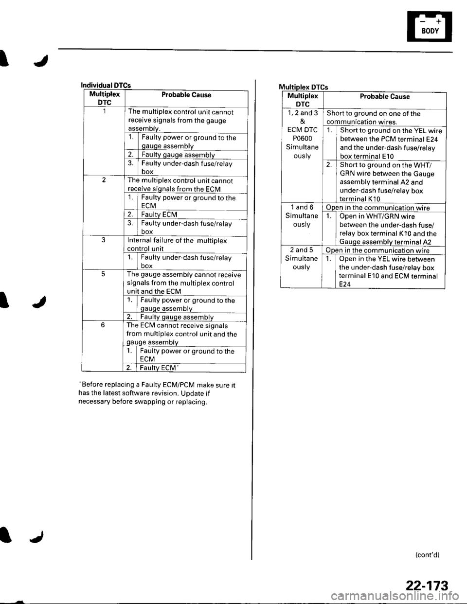
Individual
Multiplex
DTC
Probable Cause
The multiplex control unit cannot
receive signals from the gauge
assemDty.'lFaulty power or ground to thegauge assembly
2.Faulty gauge assemblv
3.Faulty under-dash f use/relay
box
The multiplex control unit cannot
receive signals from the ECM
1Faulty power or ground to the
ECM
2.Faulty ECM?Faulty under-dash fuse/relay
box
JInternal failure of the multiplex
control unit
1Faulty under-dash fuse/relay
box
5The gauge assembly cannot receive
signals from the multiplex control
unit and the ECM
Faulty power or ground to thegauge assembtv
Faulty qauge assemblv
6The ECM cannot receive signals
from multiplex control unit and thegauge assembty
1Faulty power or ground to the
ECM
Faulty ECM'
I
'Before replacing a Faulty ECM/PCM make sure ithas the latest software revision. UDdate if
necessary before swapping or replacing.
DTCs
Multiplex
DTC
Probable Cause
1,2 and 3
&
ECM DTC
P0600
Simultane
ously
Short to ground on one of the
communication wires.
Short to ground on the YEL wire
between the PCM terminal E24
and the under-dash fuse/relay
box terminal E10
2.Short to ground on the WHT/
GRN wire between the Gauge
assembly terminal A2 and
under-dash fuse/relay box
terminal K10
1and6
Simultane
ous ly
Open in the communication wire
IOpen in WHT/GRN wire
between the under-dash fuse/
relay box terminal K10 and the
Gauqe assemblV terminal 42
2and5
Simultane
ously
Open in the communication wire
1Open in the YEL wire between
the under-dash fuse/relay box
terminal E10 and ECM terminal
(cont'd)
22-173
Page 1006 of 1139
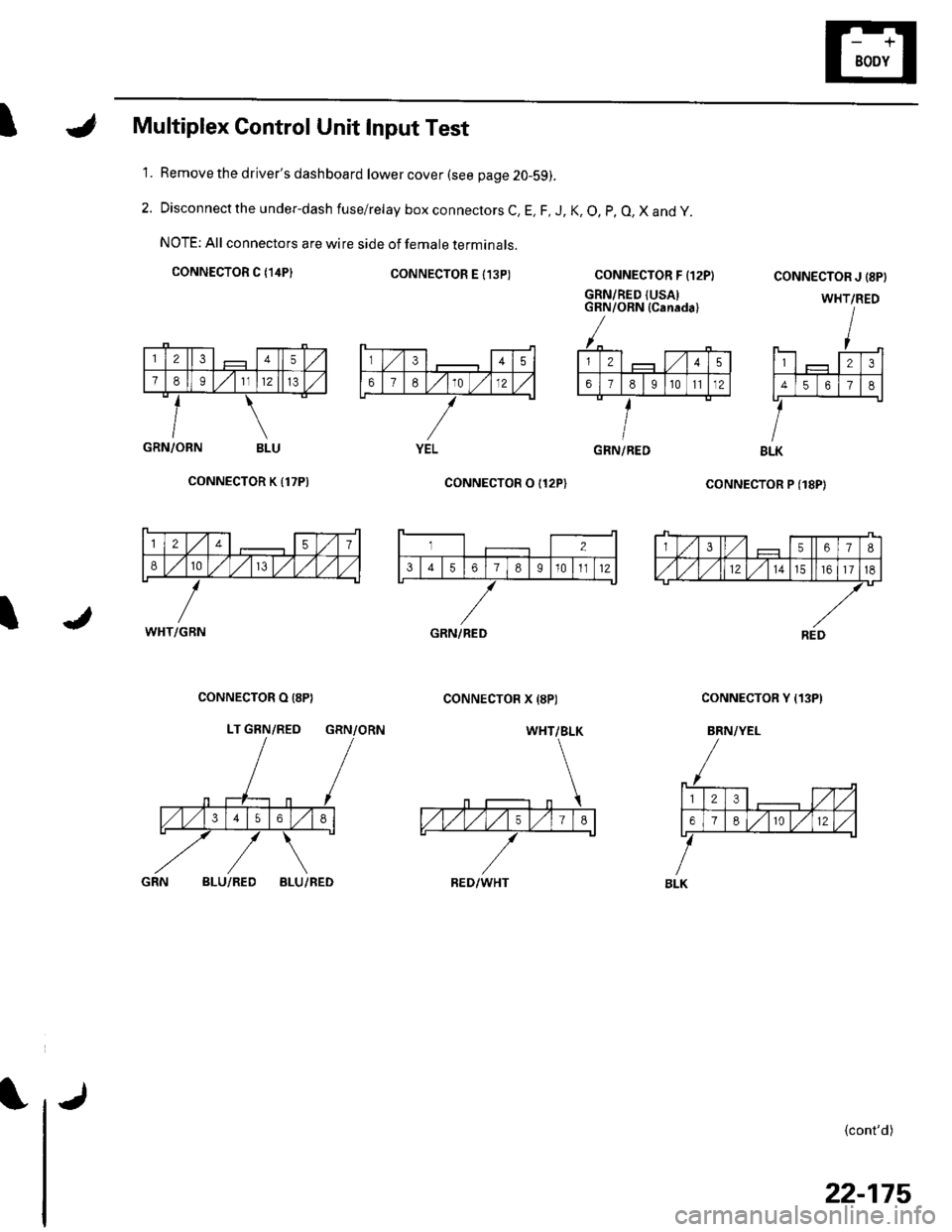
IMultiplex Control Unit Input Test
Remove the driver's dashboard lower cover (see page 20-59).
Disconnect the under-dash fuse/relay box connectors C, E, F, J, K, O, p, O, X and y.
NOTE: All connectors are wire side of female terminals.
CONNECTOR C {14P}CONNECTOR E I13P)
1.
2.
CONNECTOR F {12P}
GRN/RED {USAIGRN/ORN (Canada)
coNNECTOR P (18P)
CONNECTOR J {8PI
WHT/RED
123
4561
BLK
{cont'd)
GRN/ORN BLU
CONNECTOR K {17P)
I
CONNECTOR O I12P)
CONNECTOR X {8P)CONNECTOR O (8P}
LT GRN/RED GRN/ORN
CONNECTOR Y {13P)
BRN/YEL
BLU/REDBLU/RED
345
67E10 )./12
YELGRN/RED
12457
810/V,/ l,/
WHT/GBN
3567I
,/1,/l,/121517
REDGRN/RED
WHT/BLK
RED/WHT
23,/1,/
618r012
BLK
22-175
Page 1007 of 1139
Multiplex Control System
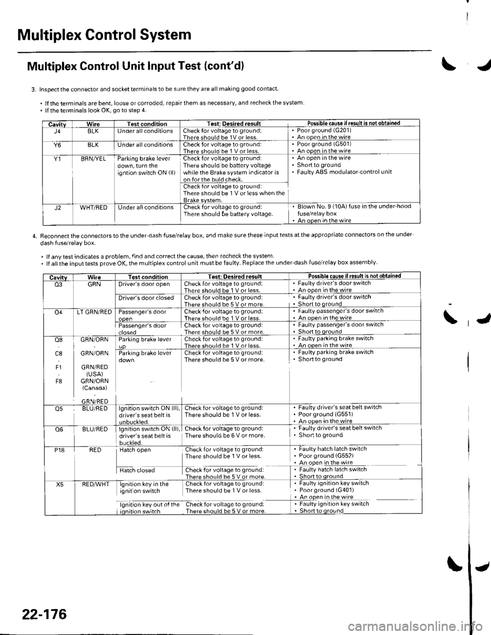
Multiplex Control Unit lnput Test (cont'd)
3. Inspect the connector and socket terminals to be sure they are all making good contact
.lftheterminalsarebent,looseorcorroded,repairthemasnecessary,andrecheckthesystem. llthe terminals look OK, go to step 4.
4. Reconnectthe connectorstothe under dash fuserelay box, and make surethese inputtests atthe appropriate connectors on lhe under-
dash fuse/relav box.
. lf any test indicates a problem, {ind and correct the cause, then recheck the system. lf allthe input tests prove OK, the multiplex control unit must be faulty. Replace the under_dash fuse/relay box assembly
CavitvWireTest conditionTest: Desired .esult r Possible cause if resullE qS!q!!e!!ed
J4BLK[J nder all conditionsCheck {or voltage 1o ground:Therc sholl.l he 1V or lessPoor ground (G20'l)An ooen in the wire
Y6BLKlJnder all conditionsCheck for voltage to ground:There should bc 1 V or less.Poor ground 1G501)An ooen in the wire
Y1BFNryELParking brake leverdown, turn theigntion switch ON (ll)
Check for voltage to ground:There should be battery voltagewhile the Brake system indicator ison forthe buld check.
An open in the wireShortto groundFaulty ABS modulatorcontrol unit
Check for voltage to ground:There should be 1V or less when the
J2WHT/REDUnder allconditionsCheck for voltage to groundiThere should be baftery voltage.Blown No.9 (10A)fuse in the under'hoodfuse/relay boxAn oncn in rhc wire
CavitvTest conditionTesi: Oesired resultPossible cause ifresult is notobtained
o3GRNDriver's door openCheck for voltage to ground:There should be 1 V or less-Faulty driver's door switchAn ooen in the wire
Driver's door closedCheck for voltage to ground:There should be 5 V or more.Faulty driver's door switchShort to qround
O4LT GRN/REDPassenger's doorCheck .for voltage 10 ground:There should be 1 V or less.Faulty passenger's door switchAn ooen inthewire
Passenger's doorCheck for voltage to ground:There should be 5 V or more.Faulty passenger's door switchShort to oround
osI]l.l
4.,
F1
F8
GRN/ORN
GRN/ORN
GRN/RED(USA)GRN/ORN(Canada)
Parking brake leverCheck for voltage to groLrnd:There shorl.l be 1 V or less.Faulty parking brake switch. An ooen in thewireCheck for voltage to ground:There should be 5 V or more.
. Faulty parking brake switchShortto ground
o5BLU/REDlgnition switch ON (ll),
driver's seat belt isCheck for voltage to ground:There should be 1V or less.Faulty driver's seat belt switchPoorground (G551)An oDen in the wire
Q6BLU/REDlgnition switch ON (ll)
driver's seat belt isbuckled.
Check {or voltage to ground:There should be 6 V or more.Faulty driver's seat belt switchShortto ground
P18RED
H",=
Check for voltage to ground:There sho0ld be 1V or less-
f -9*:li:'^:**:':s*:*
Faulty hatch latch swrtchPoor ground (G552)An open in the wireFaulty hatch latch switch
X5lgnirion key in the Check for voliage to gtound:ignit on switch Thpre should be I V or lcss
lgnrtron kev our o{ the Check for vollage to ground:
. Faulty ignition key switch. Poor ground (G401). An open in the wire
I : [11y.'::i':::1"' **6
\
22-176
Page 1021 of 1139
sRs
Precautions and Procedures
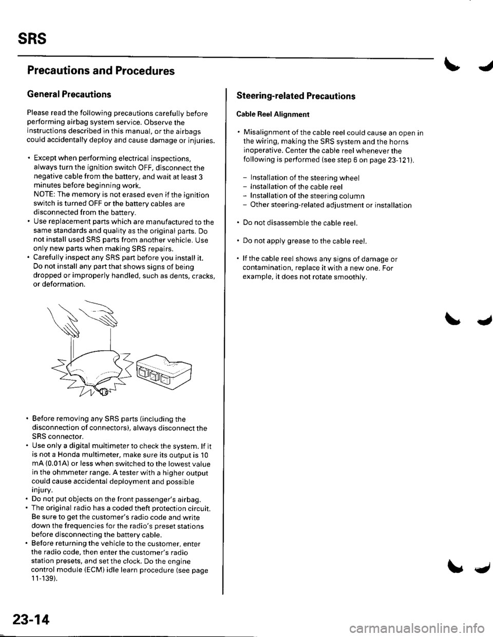
General Precautions
Please read the following precautions carefully beforeperforming airbag system service. Observe theinstructions described in this manual. or the airbags
could accidentally deploy and cause damage or injuries.
. Except when performing electrical inspections.
always turn the ignition switch OFF, disconnect the
negative cable from the battery, and wait at least 3minutes before beginning work.
NOTE: The memory is not erased even if the ignition
switch is turned OFF or the battery cables are
disconnected from the battery.. Use replacement pans which are manufactured to the
same standards and quality as the original parts. Do
not install used SRS parts from another vehicle. Useonly new pans when making SRS repairs.. Carefully inspect any SRS part before you install it.
Do not install any part that shows signs of being
dropped or improperly handled, such as dents, cracks,
or deformation.
. Before removing any SRS parts (including the
disconnection of connectors), always disconnect the
SRS connector.. Use only a digital multimeter to check the system. lf itis not a Honda multimeter, make sure its outout is 10mA (0.01A) or less when switched to the lowest value
in the ohmmeter range. A tester with a higher output
could cause accidental deployment and possible
injury.. Do not put objects on the front passenger's airbag.. The original radio has a coded theft protection circuit.
Be sure to get the customer's radio code and write
down the frequencies for the radio's preset stations
before disconnecting the battery cable.. Before returning the vehicle to the customer, enter
the radio code. then enter the customer's radio
station presets, and set the clock. Do the engine
control module (ECM) idle learn procedure (see page
11-139).
23-14
c
Steering-related Plecautions
Cable Reel Alignment
. Misalignment of the cable reel could cause an open in
the wiring, making the SRS system and the horns
inoperative. Center the cable reel whenever the
following is performed (see step 6 on page 23-121).
- Installation of the steering wheel- Installation of the cable reel- Installation ofthe steering column- Other steering-related adjustment or installation
. Do not disassemble the cable reel.
. Do not apply grease to the cable reel.
. lf the cable reel shows any signs of damage or
contamination. replace it with a new one. For
example, it does not rotate smoothly.
Page 1080 of 1139
![HONDA CIVIC 2003 7.G Workshop Manual I
g]
3
1 1. Check resistance between the No. 2 terminal of the
floor wire harness 3P connector and body ground.
There should be an open circuit. or at least 1 fvl Q ,
FLOOR WIRE HARNESS 3P CONNECTOR
W HONDA CIVIC 2003 7.G Workshop Manual I
g]
3
1 1. Check resistance between the No. 2 terminal of the
floor wire harness 3P connector and body ground.
There should be an open circuit. or at least 1 fvl Q ,
FLOOR WIRE HARNESS 3P CONNECTOR
W](/manual-img/13/5744/w960_5744-1079.png)
I
g]
3
1 1. Check resistance between the No. 2 terminal of the
floor wire harness 3P connector and body ground.
There should be an open circuit. or at least 1 fvl Q ,
FLOOR WIRE HARNESS 3P CONNECTOR
Wire side ot temale terminals
ls the resistance as specified?
YES-Go to step 12.
NO Short to ground in the floor wire harness or
multiplex control unit. Replace the faulty harness or
part.I
Check resistance between the No. 3 terminal of the
floor wire harness 3P connector and body ground.
There should be an open circuit, or at least 1 M Q.
FLOOR WIRE HARNESS 3P CONNECTOR
LT GRN
Wire side of female terminals
ls the resistance as specified?
YES Go to step 13.
NO-Short to ground in the floor wire
replace the floor wire harness.I
12.
13. Check resistance between the No. 8 terminal of
SRS unit connector C (8P) and the No. 3 terminal of
the floor wire harness 3P connector. There should
be0 1Q.
FLOORWIRE HARNESS SRS UNITCONNECTORC I8P}3P CONNECTOB
Wire side of female terminals
ls the resistance as specitied?
YES Go to step 14.
NO Open in the floor wire harness; replace the
floor wire harness.l
Check resistance between the No. 4 terminal of
SRS unit connector C (8P) and the No. 2 terminal of
the floor wire harness 3P connector. There should
be0-1 0.
14.
FLOOR WIRE HARNESS3P CONNECTORSRS UNIT CONNECTOR C IsPI
Wire side of female terminals
ls the resistance as specified?
YES Replace the SRS unit (see page 23-122).1
NO Open in the floor wire harness or multiplex
control unit, or poor connection at the floor wire
harness, the under-dash fuse/relay box, and the
multiplex control unit. Check the connection at the
floor wire harness, the under-dash fuse/relay box,
and the multiplex control unit. lf the connection is
OK, replace the faulty harness or part.l
harness;
23-73
Page 1126 of 1139
)
3.
4.
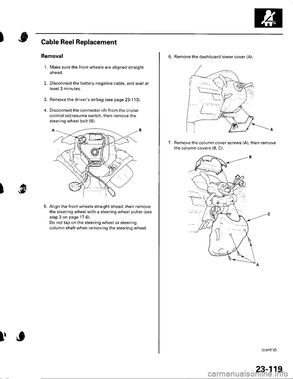
Cable Reel Replacement
Removal
1. Make sure the front wheels are aligned straight
ahead.
Disconnect the battery negative cable, and wait at
least 3 minutes.
Remove the driver's airbag {see page 23-113).
Disconnect the connector (Al from the cruise
control sevresume switch, then remove the
steering wheel bolt (B).
Align the front wheels straight ahead, then remove
the steering wheel with a steering wheel puller (see
step 3 on page '17-6).
Do not tap on the steering wheel or steering
column shaftwhen removing the steering wheel.
)
5.
I,
6. Remove the dashboard lower cover (Ai.
Remove the column cover screws (A), then remove
the column covers (8, C).
7.
(cont'd)
23-119
Page 1128 of 1139
)
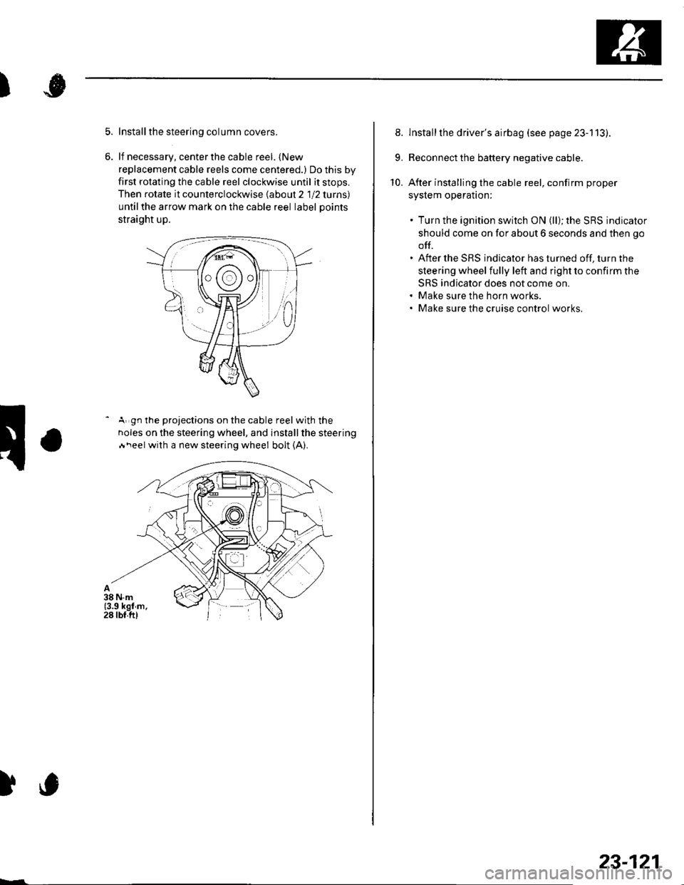
Install the steering column covers.
lf necessary, center the cable reel. {New
replacement cable reels come centered.) Do this by
first rotating the cable reel clockwise until it stops,
Then rotate it counterclockwise labout 2 1 12 lurns)
untilthe arrow mark on the cable reel label Doints
straight up.
- A gn the projections on the cable reel with the
noles on the steering wheel, and installthe steering
Ai\eel with a new steering wheel bolt (A).
)c
23-121
8. lnstallthe driver's airbag (see page 23-113).
9. Reconnect the battery negative cable.
10. After installing the cable reel, confirm proper
syslem operalton:
. Turn the ignition switch ON (ll); the SRS indicator
should come on for about 6 seconds and then go
off.. After the SRS indicator has turned off, turn the
steering wheel fully left and right to confirm the
SRS indicator does not come on.. Make sure the horn works.. Make sure the cruise control works,
Page 1133 of 1139
Service Manual lndex
)s
NOTE: Referto the lollowing listto look up A/C Pressure Switch CircuitDTCS, symptoms, fuses, connectors, wire Troubleshooting ......... ...-.-....-...-.-.-....-..21-32 Bharnesses, specifications, maintenanceschedules, and general serviceinlormation:
DTC Troubleshooting Indexes
A/C Signal CircuitTroubleshooting.........................-...... 11-'133 Back-up Light SwitchTest .......................................................... 13'3A/F lAir Fuel Ratiol SensorABS/TCS Components ........................ 19-34 Replacement ....................................... 1 1-113 Back-up Li9ht3EPS Components ................................. '17-22 Circuit DiagramFueland Emissions11-i A-Dillar Corner Trim
ABS Indicator Circuit
Heating/Ventilation ................................ 21-9 Replacement ...............-.....-..............-.... 20,96 Ball Joint BootssRS ........................................................ 23-28Replacement ......
... 19-52 Ball Joints
22-75
18 16
Remova1.............-.......... . ...........18-10Symptom Troubleshooting Indexes TroubleshootingABS/TCSComponents........................ 19 35Cruise Control System ..........................4 38 ABS Modulator-contml UnitEPS Components ................................. 17-23 Bemoval/lnstallation ............................ 19-57 BettervFan Controls10,12
Accessory Powor Socket Front
Blowor Pow€r Transistor
.......22 50
Blower UnitRemoval/lnstallation ............................ 21-39
Fuel and Em issions .............................. 11-10 ABS/TCS ComoonentsHeating/Ventilation..............................21 10 Component Location Index ................. 19-30 Beverage Holder
SRS ........................................................ 23'30 CircuitDiaqram.......................... 19'42Blower MotorReplacement .....21 41
21-38
Power 0istribution ...............................22-46 TesVReplacement .............................. 22'149Under-dash Fuse/Relay Box ............... 22 45Under-hood Fuse/Belay Box ...............22 44 Accessory Power Sockets
Fuse/Relay lndexes
(to harness)
Connector and Wire Harness lndexesComponent Connectors
Circuit Oiagram .................................. 22-149
Air Cleaner......2214 Rep1acemen1.....................................11-162
Air MixControl MotorMeintenence section .................... Section 3 Replacement ......................................... 21'34 Brake CelipersTest......................21-34 Overhaul19-14,23Gene.al lnlormation section........ Section 1
21.57
Airbag. Driver's
Ahernator FR Signal CircuitTroubleshooting .... .........-..........11 134
AntennaReplacement
Inspection ............................................. 19-24Rep|acement................. .................... 19-25
Bieke Meder Cylinder
Irake Discs
A
Replacement ....................................... 23 1 'l3 Inspection .................... ................... 19-13,22Repair ...........-...................................... 23 1 16Brake Fluid Level SwitchAirbag. Front Passenger's TestBeplacement....................................... 23-1 14AIC Brake LightsComponent Location fndex ...................21-3 Altemator CircuitDiagram....................................22-74Description.....................................-....21'1'l Beplacement ................ ........................... 4 29CircuitDiagram....................................21-14 Overhaul .................................................4-30 Brake Lines and Hoses
19.10
A/C CompressolReplacement .......-...-............................. 21 -41
A/C Compr€ssor ClulchRep1acement......................................... 19-15.........22-103 Inspection ............................................. 19-16Inspecton........Overhaul ..........
A/C CondenserReplacement,.,
21-442l-49 Audio Unit
Replacement
Brake PadsRemoval/lnstallation .. ........................22-100 Inspection/Rep1acement................ 19-11,20A/C Compressor Clutch CircuitTroubleshooting ................................... 21-30 Audio Unit Connector Brake Pedal22101 Adjustment..............19,6ArfC Comoressor Relief ValvcReplacement ..........-...-.......................... 21-51 Audio/Entertainment
A/C Compr$sor Thermal Protector Circuit DiagramReplacement............-............................ 21-51
Component Location In dex .................22-9A Test .......-.............. 22-84Breke Pedal Posilion Switch
Brake Pedal Position Switch Signal Clrcuit11-137
.....21 52
A/C Condenser Fan CircuitTroubleshooting ................... . . . . . .....21-28
)s
Troubleshooting
(cont'd)