2003 HONDA CIVIC switch
[x] Cancel search: switchPage 829 of 1139

Heating and Air Conditioning
A/C System Tests (cont'd)
1.
Performance Test
Air conditioning refrigerant or lubricant vapor
can irritate your eyes, nose, or throar.
Be carefulwhen connecting service equipment.
Do not breathe refrigerant or vapor.
The performance test will help determine if the air
conditioner system is operating within specifications.
Use only service equipment that is U.L.-listed and is
cenified to meet the requirements of SAE J2210 toremove HFC-134a (R-134alfrom the air conditioning
system.
lf accidental system discharge occurs, ventilate the
work area before resuming service
R-134a service equipment or vehicle air conditioning
systems should not be pressure tested or leak testedwith compressed air.
Additional health and safety information may be
obtained from the refrigerant and lubricant
manufacturers.
Connect a R-134a refrigerant recover/recycling/
charging station to the high-pressure service port
and the low-pressure service port, following the
equipment manufacturer's instructions.
Determine the relative humidity and air
Iemperaru re.
' Compressed air mixed with R-134a forms a
combustible vapor.. The vapor can burn or explode causing serious
Injury.. Never use compressed air to pressure test
R-134a service equipment or vehicle air
conditioning systems.
21-58
4.
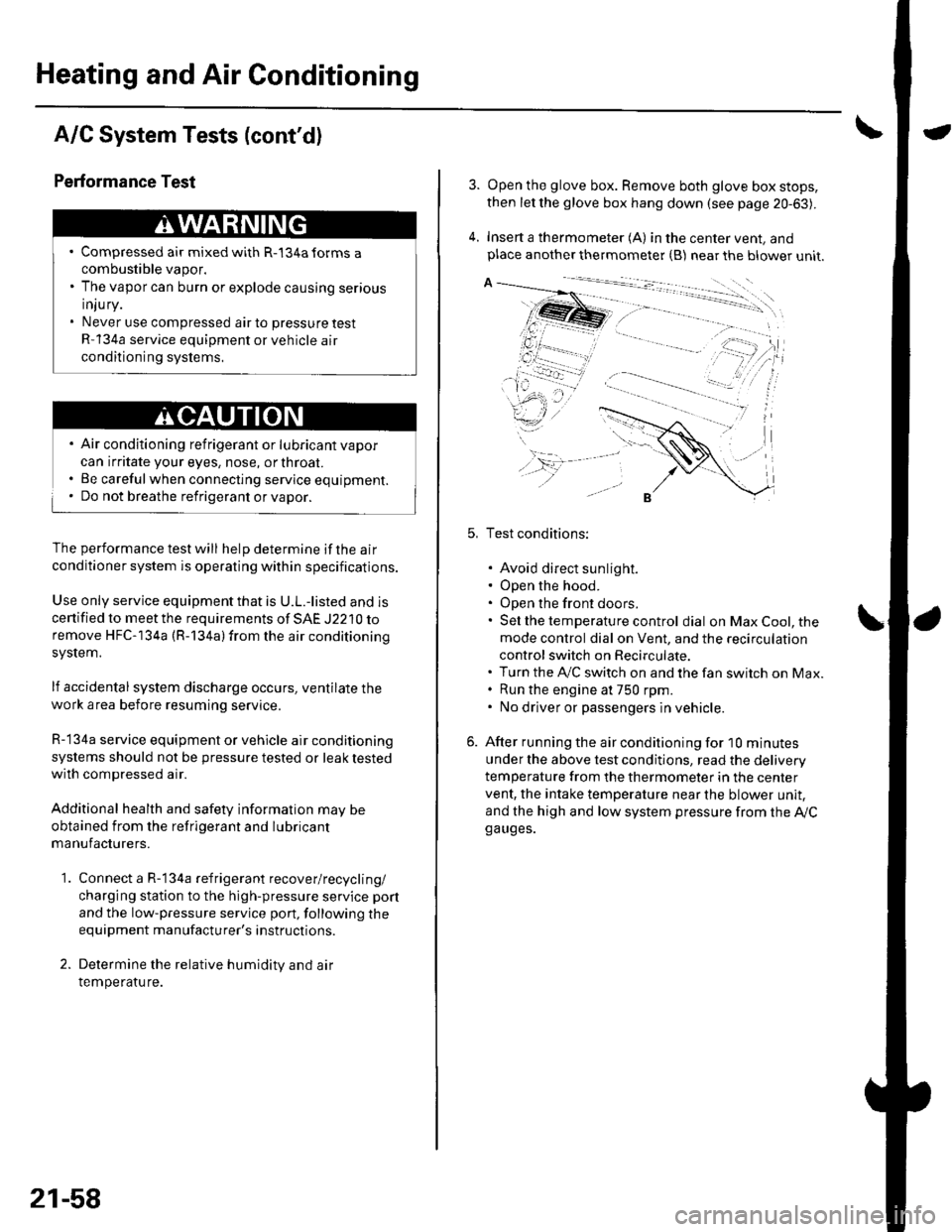
Open the glove box. Remove both glove box stops,
then let the glove box hang down (see page 20-63).
Insert a thermometer (A) in the center vent, andplace another thermometer {B) near the blower unit.
Test conditions:
. Avoid direct sunlight.. Open the hood.. Open the front doors.. Sel the temperature control dial on Max Cool, the
mode control dial on Vent, and the recirculation
control switch on Recirculate.. Turn the A,/C switch on and the fan switch on Max.. Run the engine at 750 rpm.. No driver or passengers in vehicle.
After running the air conditioning for I0 minutes
under the above test conditjons, read the delivery
temperature from the thermometer in the center
vent, the intake temperature near the blower unit,
and the high and low system pressure from the Ay'Cga uges.
Page 831 of 1139

\Body Electrical
Body ElectricalSpecialToolsGeneral Troubleshooting tntorrnaiion.'......
Relay and Control Unit Locations .....
Connectors and Harnesses
Fuse/Relay Boxes ...............................
Power Distribution .............................
Ground Distribution ...........................
Under-dash Fuse/Relay Box ..............
Battery ..............
Relays ................
*lgnition Switch ..............
*Gauges
Component Location Index .......................Self-diagnostic Procedure ..........................Circuit DiagramGauge Bulb Replacement ..........................Gauge Assembly ReplacementCoolant Temperature
Gauge Troubleshooting .... ....................Vehicle Speed Signal CircuitTroubleshootingVSS Replacement
Exterior LightsComponent Location Index .......................Circuit DiagramDaytime Running Lights ControiUnit Input Test (Canada) ........................Headlight Ad,ustment .................. .. .....Headlighr Replacement ..............................Combination Light SwitchTest/ReplacementBulb ReplacementTaillight Replacement ..........................High Mount Brake Light Replacement ......License Plate Light Replacement ..............Side Marker Light Replacement ................Brake Pedal Position Switch Test ..............Side Turn Signal Light Replacement ........
Turn Signal/HazardFlasher SystemComponent Location Index .......................Circuit DiagramTurn Signal/Hazard Relay lnputTest ........Hazard Warning Switch Test
22,3
22-7
22-13
22-44
22-46
22-4A
22-49
22-50
22-51
22-53
22-5422-5622-5422 6322-64
22-64
22-6522 61
22-6822--71
22-7 622-7422-79
22-AO22-4122-8222-4222-4322-4322-4422-84
22-8�522 A622-8722-88
22-10422-105
22-10622-107
Entry Lights control systemComponent Location Index ....................... 22-89Circuit Diagram ......... 22 90lgnition Key Switch Test .....................,...... 22-9'llgnition Key Light Test ............................... 22-91Control Unit Input Test ..........,.................... 22 92
Interior LightsComponent Location Index ....................... 22-94Circuit Diagram ......... 22-95Ceiling LighVSpotlightsTesVReplacement ................................... 22-96Rear Ceiling Light TesVReplacem ent ........ 22-96Cargo Area Light Test/Replacem ent ......... 22-97Hatch Latch Switch Test ..,..,....................... 22-97
*Audio SystemComponent Location Index ....................... 22-98Circuit Diagram ......... 22,99Audio Unit Removal/lnstallation ............... 22-1OOAudio Unit Connector Replacement ......... 22-101Speaker Replacement ................................ 22-102Roof Antenna Rep1acement ....................-.. 22-103
Rear Window DefoggerComponent Location Index ...........Circuit Diasram .. ....... .. ..... ....... ...:::::.::.::.Function TestDefogger Wire Repair .................................Noise Condenser CapacityTest ................
MoonroofComponent Location Index ....................... 22-1OBCircuit Diagram ......... 22-109Moonroof Control Unit Input Test ............. 22-'l10Switch TesVReplacement ........,.....,........... 22-1 12Motor Test ................. 22-112Limit Swilch Test ...... 22-'l'13Auto-stop Switch Test ................................ 22-1 13
Power MirrorsComponent Location Index ....................... 22-114Circuit Diagram ......... 22-115Function Test ............. 22-116Power Mirror Switch Test .......................... 22-ll7Power Mirror Actuator Test ....................... 22-117Power Mirror Actuator Replacement ........ 22-11A
* HornsComponent Location Index ....................... 22-120Circuit Diagram ......... 22-121Horn TesVReplacement ...........................-. 22-122Horn Switch Test .,.... 22-122
\
Page 832 of 1139

Power WindowsComponent Location Index ..........
circuit Diagram . .. ............... .........:.::::.::::.:Master Switch Input Test ...........................Master Switch TestDriver's Window Motor Test .....................
Passenger's Window Switch lnput Test ...Passenger's Window Switch Test .............
Passenger's Window Motor Test ..............
lMaster Switch Replacement ......................
Passenger's Window SwitchReplacement
Wipers/WashersComponent Location Index .......................
Circuit DiagramRear Window Wiper Intermiftent
Control Unit Input Test ...........................Wiper/Washer SwitchTesVReplacementControl Unit Input Test ...............................Wiper Motor Test
Washer Motor TestWasher Fluid Level Switch TesV
Replacement (Canadal ..........................
Windshield Wiper Motor Replacement ....
Rear Window Wiper MotorReplacementWasher Reservoir Replacement ................
Washer Tubes Beplacement ......................
Accessory Power SocketCircuit Diagram ......... 22-149
Accessory Power Socket
TesVReplacement ................................... 22-1 49
Keyless/Power Door Lock System
Component Location Index ....................... 22-150
Circuit Diagram ......... 22-151Keyless Receiver Unit InputTest ............... 22-153
Control Unit Input Test ............................... 22-155
Door LockActuatorTest .........,.......,..,.,..... 22-158Hatch LockActuatorTest ........................... 22-159
Door Lock Knob Switch Test ...................... 22-160
Door Lock Switch Test ................................ 22-160
Transmitter Test ....... 22-161
Transmitter Programming ......................... 22-161
Multiplex Control SystemComponent Location Index ...........
circuit Diagram ...... ........................::.:..:.::.:
Svstem DescriDtionTroubleshootingMultiolex Control Unit InDut Test .............
22 12422-12522-12622-12822-129
22- t30
22-13222 13222-133
22-133
22-134
22-138
22-14022-14122-14322-144
22-14422-145
22-14622-14622 147
22,16422-16922-17'l22,11222-175
lmmobilizer Systemcomponent Location Index ...........
System Description ....... ............. ..:..:..:.:...
Circuit DiagramTroubleshootinglmmobilizer Control Unit-Receiver Replacement ...........................
22-16222-16322-164
22-167
Page 843 of 1139
![HONDA CIVIC 2003 7.G Workshop Manual Relay and Control Unit Locations
Door and Seat
Drivers Door:
Passengers Seat:
l\:
].\
POWER WINDOW MASTER SWITCHlHas built-in control unit)
22-12 HONDA CIVIC 2003 7.G Workshop Manual Relay and Control Unit Locations
Door and Seat
Drivers Door:
Passengers Seat:
l\:
].\
POWER WINDOW MASTER SWITCHlHas built-in control unit)
22-12](/manual-img/13/5744/w960_5744-842.png)
Relay and Control Unit Locations
Door and Seat
Driver's Door:
Passenger's Seat:
l\:
].\
POWER WINDOW MASTER SWITCHlHas built-in control unit)
22-12
Page 847 of 1139

Connectors and Harnesses
Engine Wire Harness
Camshaft position (CMP) sensorLllr sensorEC[,4 connector AECI/l connector BEngine coolant temperature (ECT)
sensorEngine oil pressure switchEVAP canister purge valveldle air control (lAC)valve
lgnition coil No. llgnition coil No. 2lgnition coil No. 3lgnition coil No. 4Iniector No. 1Inlector No.2Iniector No.3Iniector No. 4Intake air temperature {lAT) sensor
TDC sensorThrottle position (TP) sensorVehicle speed sensor (VSSI
VTC oil control solenoid valveVTEC oil pressure switchVTEC solenoid valvec 101
c102
233
242
Transmission housingLeft side of engineRight side ofengineUnder glove boxUnder glove boxLeft side of engine
Bight side oI engineLeft side of intake manifoldLeft side of intake manifoldMiddle of engine compartmentMiddle of engine compartmentMiddle of engine compartmentMiddle of engine compartmentMiddle of engine compartmentMiddle of engine compartmentMiddle of engine compartmentMiddle of engine companment
28
1845672524201912
811102729303
22
12333332222233
322220
Left side of intake manifoldLeft side of engineLeft side of intake manifoldTransmission housingRight side o{ engineRight side of engineRight side of engineUnder right side of dash
Front of engine companment
Front of engine compartment
ECM wire harness {see page22-321Starter subharness (see page22-15)Starter subharness (see page22 151
Connector to Harness Index (cont'dl
22-16
Page 849 of 1139

Connectors and Harnesses
Connector to Harness Index {cont'dl
Engine Compartment Wire Harness (Right branch)
\
Connsctor or TerminalCavitissLocationConnects toNotesABS modulator-control unitBearwasher motorRight front ABS wheel sensorRight front airbag s€nsorBightfront parking lightRight front side marker lightRight front turn signal lightRight headlightRight hornwash€rfluid level switchWindshield washer motor
812
110112
7
222222
I22
Bight side o{ engine compartmentBehind right side of {ront bumperRight side ot engine compartmentBehind right side of front bumperBehind right headlightBehind rightside of Jront bumperBehind right headlightBehind right headlightBehind front bumperBehind rightside of tront bumperBehind rioht side of front bumoerCanada
G202
G2016Behind rightside of tront bumper
Behind rightside of Jront bumper
Body ground via €nginecompartment wtre harnessBody ground via engine.omnerhent wire harness
22-18
Page 851 of 1139

Connectors and Harnesses
Engine Compartment Wire Harness (Left branch)
AirJuel (A,,/F) ratio sensorBrake fluid level switchCondenser fan motorCruise control actuatorELD unitFog light connectorLeft front ABS wheel sensorLeft front airbag sensorLeft front parking lightLeft front side marker lightLeft lrontturn signal lightLeft headlightLeft hornRadiator fan motorRadiator fan switchSecondary heated oxygen (SHO2S)
Test tachometer connectorWindshield wiper motorUnder'hood fuse/relay boxconnector A {see page 22-44)Under-hood f use/relay boxconnector B (see page 22-44)Under hood fuse/relay boxconnector C (see page 22-44)Under hood fuse/relay boxconnector D (see page 22 44)Under-hood fuse/relay box
Front of engine companmentLeft side of engine compartmentLeft side of engine compartmentLeft side o{ engine compartmentFront of engine compartmentUnder right side of cowl coverUnder'hood f use/relay boxLeft side of engine compartmentLeft side of engine companmentBehind left side of front bumperBehind left headlightBehind left side of front bumperEehind left headlightBehind left headlightBehind front bumperLeft side of engine compartmentFront of engine compartmentLeft side of engine compartment
Left side of engine companmentL.Jnder left side of cowl coverL.Jnder hood fuse/relay box
L.Jnder hood fuse/relay box
L.Jnder'hood f use/relay box
underhood fuse/relay box
Under-hood fuse/relay box
24222
2519
12
17
13202123
3
117
I
10
5
6
l2
2243,l
222223l224
252
5
12
Connector to Harness Index (cont'dl
\
22-20
Page 857 of 1139

Connectors and Harnesses
Dashboard Wire Harness A {Left branchl
Connector or TerminalffiAccessory power socketAudio antennaBrake pedal position switchClutch interlock switchClutch pedal poistion switchCruise control unitCruise main switchDaytime r!nning lights control unitDaytime running lights relayGauge assembly connector AGauge assembly connector BHazard warning switchHeater control panel connector AHeater control panel connector BHVAC push switch assemblyKeyless receiver unitLow beam cut relayOptional security connectorPower mirror switchUnder-dash fuse/relay boxconnector K (see page 22-45)Under'dash fuse/relay box
L {see page 22-45}Underdash fuse/relay boxconnector M lsee page 22'45)Under-dash fuse/relay boxconnector N (see page 22-45)UndeFdash fuse/relay boxconnector O (see page 22-45)UndeFdash fuse/relay boxconnectorY (see page 22 45)c504
c505
c506
c507
c508
c509
c510
22226
3029628
I820111819105327
,I4
12
11
34
1
24
25
2 Under middle of dash2 Under left side of dash4 ] Under left side of dash2 ] Under left srde of dash2 | Under left side of dash14 I Under left side of dash5 Under left side of dash14 Under lett side of dash4 Under lett side of dash22 I Behind gauge assembly22 i Behind gauge assembly10 Behind hazard warnning switch22 Behind heater control panel'14 Behind heater control panel10 ] Behind HVAC switch assembly5 I Under middle of dash5 lUnderleftsideofdash16 Under lefr side of dash13 Under left side oI dash17 ln the under-dash fuse/relay box
CanadaCanada
l0In the under-dash fuse/relay box
In the undeFdash fuse/relay box
In the underdash fuse/relay box
In the under-dash fuse/relay box
In the under-dash fuse/relay box
Under left side of dash
Under left side ot dash
Under left side of dash
Under left side of dash
Under middle of dash
Under middle of dash
Under middle ol dash
Driver's door wire harness(see page 22'40)Driver's door wire harness(see page 22-40)Left side turo signal lightsuonarnessRoof wire harness (see page22 3AlFloor wire harness {see page22-341Floor wire harness (see page22 34JDashboard wire harness B(see oaoe 22-30)
12
12
G501
G503
1
21
Under gauge assembly
Under left side of dash
Body ground via dashboard
Body ground via dashboard
Left Side Turn Signal Light Sub harness
Connector to Harness Index (cont'd)
L
Connector or TerminalCavitiesLocationConnects toNolesLeft side turn signal lightc506353422Behind left side turn signal lightUnder left side of dashDashboard wire harness A
22-26