Page 579 of 1139
Special Tools Required
Ball joint remover,28 mm 07MAC-S100200
Removal
1. Raise the front of the vehicle, and support it with
safety stands in the proper location (see page 1-8).
Remove the front wheels.
Remove the cotter pin (A) from the tie-rod end ball
ioint, and remove the nut (B).
10 mm HEX NUT
07MAC-S1002000
Disconnectthe tie-rod end from the steering arm
on the damper using the specialtool (see page 18-
10 ).
Remove the bolts, and remove the wheel sensor
harness bracket {A) and brake hose bracket (B)
from the damper. Do not disconnect the wheel
4.
sensor connector.
A6x1.0mm
/.8
x 1.25 nm
q
5. Remove the damper pinch bolts (A)while holding
the nuts (B).
6. Remove the flange nuts (A)from the top ofthe
damper,
A10 x 'l.25 mm
7. Lower the lower arm, and remove the damper
assembly (B).
(cont'd)
18-21
Page 583 of 1139

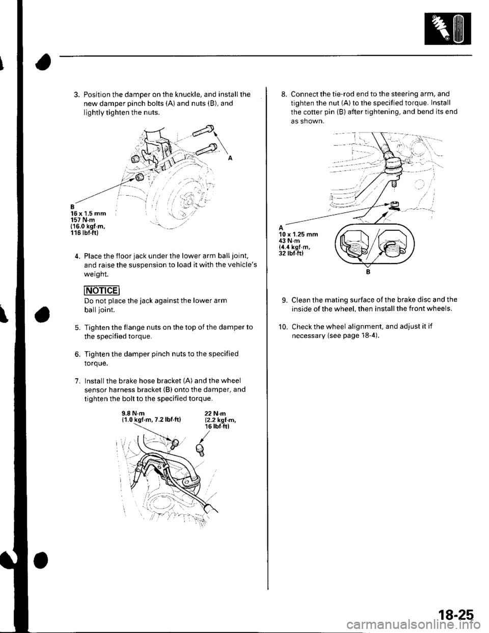
3. Position the damper on the knuckle, and installthe
new damper pinch bolts (A) and nuts (B), and
lightly tighten the nuts.
B16x 1,5 mm157 N.m(16.0 kgt m,116 tbt.ftl
4. Place the floor jack under the lower arm balljoint,
and raise the suspension to load it with the vehicle's
weight.
Do not place the jack against the lower arm
balljoint.
Tighten the flange nuts on the top of the damper to
the specified torque.
Tighten the damper pinch nuts to the specified
torque.
Install the brake hose bracket (A) and the wheel
sensor harness bracket (B) onto the damper, and
tighten the bolt to the specified torque.
5.
1.
9.8 N.m11.0 kgf.m, 7.2lbf.ftl22N|rl.12.2 kgI m,16 rbr,ftl
q
8. Connect the tie-rod end to the steering arm, and
tighten the nut (A) to the specified torque. Install
the cotter pin (B) after tightening, and bend lts end
as shown.
9. Clean the mating surface ofthe brake disc and the
inside of the wheel, then install the front wheels.
10. Check the wheel alignment, and adjustitif
necessary {see page 18-4).
18-25
Page 729 of 1139

Front Seat Cover Replacement
For some models: SRS components are located in this
area. Review the SRS component locations (see page
23 13) and the precautions and procedures (see page
23-'14) in the SRS section before performing repairs or
service,
NOTE:. Take care not to tear the seams or damage the seat
covers,. On the passenger's seat with side airbag, do not
touch the OPDS sensor in the seat-back pad, and keep
it away from oil. Oil can corrode the sensor causing it
to fail.. Put on gloves to protect your hands.
Seat-back Cover
Remove the front seat isee page 20-71).
With side airbag: From under the seat cushion,
detach the side airbag connector clip (A), and on
the passenger's seat, detach the OPDS unit
connector clip (B). Release the hook springs (C)
from the seat cushion frame spring {D), then pull
the guide cover (E) back, and remove the wire ties
(F). The passenger's seat is shown, the driver's seat
is svmmetrical except it has no OPDS unit
connector.
'L
2.
3.Fold the seat-back forward.
Release the hooks (A), and unzip the seat-back
cover (B).4.
(cont'd)
20-75
Page 1139 of 1139

SuspensionAdjustment................-............................184 VComponent Location Index................. 20-17
Windshield GlessReplacement............-..............-............. 20 19
Synchro Ring, Triple-coneInspection...............-..........................1339 ValveGuides
Synchro SleeveInspectaon/Reassemb1y ....................... 13 39
Inspection ............-.-................................ 6 32Beplacement ..........-................................ 6 33 Wiper Intermittent Control Unit,Rear WindowInput Test
T
Valve SeatsRepair ...................................................... 6 35.....22-134
WiDer Motor, Rear WindowRep1acement....................................... 22-1 46Adjustment .-.-.......Removal ...-...-......................................-... 6-31 WiDer Motor, windshield6-9
.....6-32 Test.......-..........-.....-.............................22-143Taillight
ThermostaiTest ........................
Inspec!on
Vehicle Speed Signal Circuit
VTC System
Wiper/WasheI
Wi.ing System
10 4 Troubleshooting .....-... ..........................22-65 Component Location In dex ..............22-134Replacement.....-...-....... ...................... 10 IvssThrottle BodyTest ..................Removal/lnstallation .. . . . . . .. ... 11-'165 VTC ActuatorDisassembly/Feassemb|y................-11-166 Inspection
Circuit Diagram .......................... 22-136, 131
Replacement -.............. ............ .............22 61 Wiper/Washor SwitchTesVReplacement .............................. 22-1 40
.................68 WireHarnesses
11-160
Replacement ........................................... 6 24 (Seefirstpageofthislndex)Throttle CableAdjustment ...... ...-.................... 11163 VTC Oil ConlrolSolenoid ValveRemoval/1nsta11ation..........................11164 Removal....-...-... |1-127 HowtoIn{ormation ...............................223Belay and Control UnitLocations .-....-.............. -.-.-....- 22-7, 4, 1 1, 12Beplacement.........-............................... 1767 ComponentLocationlndex.............. 11-117Tie-rod Ball Joint Boots
lnstallation
Replacement
Turn Signal/Hazard Relay
tsTiming/Cam ChainVTEC Solenoid Valve...612 Femoval/lnspection....-......................11-128................ 6 15
Timing/Cam Chain Auto-tensionelRemoval/1nsta11ation..............................6-19 W
Troubleshooting{See first page ot this Index)
Turn Signal Light
Timing/Cam Chain CaseOil SealInstallation......................-......................6,21 Washer Fluid Level SwitchTesVReplacement .............................. 22 1 44Trailing ArmsRemoval/lnstallation .............. . . . . ..... 18 33 Washer Fluid ReservoirReplacement ....................................... 22-1 46tnmComponent Location lndex ................- 20 49 Washer Motor, WindshieldRemoval/lnstallation ..-.......20 50,51,52,53 Test -..............-.............. ........................22 144
Washer Tube, WindshieldReplacement......-...-............................ 22 1 47
W.ter Outlet.........22 A4 Installation ..................-........................... '10-9
InputTest........22-87 lnstallation................ 10IWeter Passage
Wheels andTires
Turn Signal/Hazard Warning Lights Water PumpComponent Location In dex .................22 85 Inspection ........................... .. . . . ....... 10 5Circu it Diagram ................-................... 22-86 Replacement .-......................................... 10 5
U
WheelBearingsInspec|ion ....................................... ....... 18 8
Wheel Speed SensorsInspection ..-..,.,.,,.,,,,,.,.,,,...................... 19-59Replac€ment ........-....... . . . . . . .. -.... 19-59UndeFdash Fuse/R€lay BoxRemoval/lnstaf lation ............................ 22-49
Upper ArmsRemoval/|nsta11ation................. ... 18-32
],sInspect|on
Page:
< prev 1-8 9-16 17-24