2003 HONDA CIVIC replace indicator relay
[x] Cancel search: replace indicator relayPage 1114 of 1139

JI
I
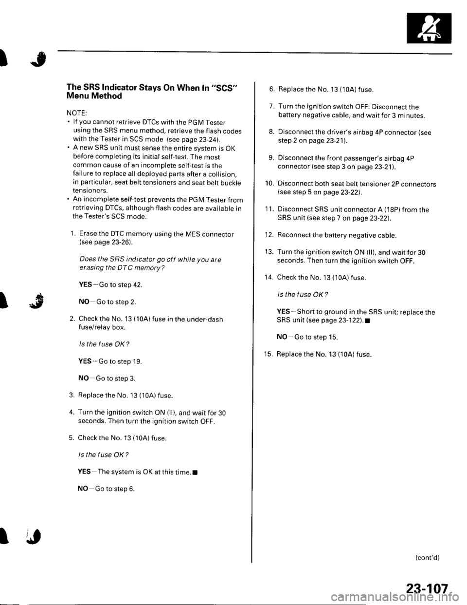
The SRS lndicator Stays On When ln "SCS"
Menu Method
NOTE:. lf you cannot retrieve DTCSwith the PGM Tester
using the SRS menu method. retrieve the flash codeswith the Tester in SCS mode {see page 23-24|,.. A new SRS unit must sense the entire system is OK
before completing its initial self-test. The most
common cause of an incomplete self-test is the
failure to replace all deployed parts after a collision,
in particular, seat belt tensioners and seat belt buckletenstoners.. An incomplete self-test prevents the PGM Tester fromretrieving DTCS, although flash codes are available in
the Tester's SCS mode.
1 . Erase the DTC memory using the MES connector(see page 23-26).
Does the SRS indicator go off while you are
erasing the DTC memory?
YES-Go to step 42.
NO Go to step 2.
Check the No. '13 { 10A) fuse in the under-dash
fuse/relay box.
lsthe f use OK?
YES--Go to step 19.
NO Go to step 3.
Replacethe No. 13 (10A) fuse.
Turn the ignition switch ON (ll), and wait for 30
seconds. Then turn the ignition switch OFF.
Check rhe No. 13 (10A) fuse.
ls the f use OK?
YES The system is OK at this time.I
NO Go to step 6.
3.
I
6. Replace the No. 13 (10A) fuse.
7. Turn the ignition switch OFF. Disconnect the
battery negative cable, and wait for 3 minutes.
8. Disconnect the driver's airbag 4P connector (see
step 2 on page 23-21).
9. Disconnect the front passenger's airbag 4P
connector (see step 3 on page 23,21).
10. Disconnect both seat belt tensioner 2P connectors(see step 5 on page 23-221.
'11. DisconnectSRS unitconnectorA{18P)fromthe
SRS unit (see step 7 on page 23-22],.
'12. Reconnect the battery negative cable.
13. Turn the ignition switch ON (ll), and wait for 30
seconds. Then turn the ignition switch OFF.
14. Checkthe No. 13 ('10A) fuse.
ls the f use OK?
YES-Short to ground in the SRS unit; replace the
SRS unit (see page 23-122).a
NO Go to step 15.
15. Replace the No. 13 (10A) fuse.
{cont'd)
23-107
Page 1115 of 1139

sRs
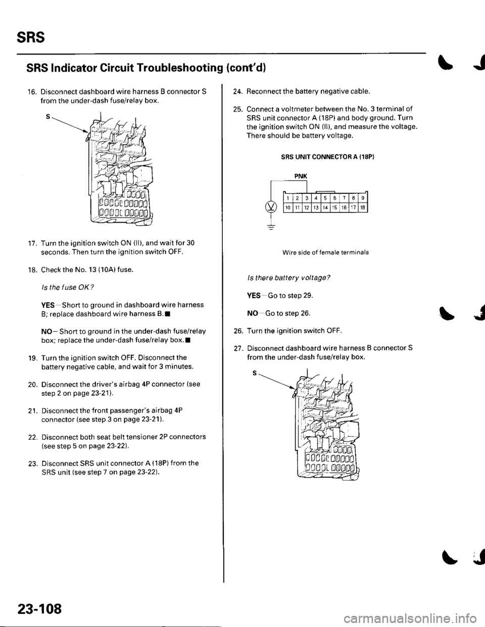
from the under-dash fuse/relav bor.
11.
18.
SRS Indicator Circuit Troubleshooting (cont'd)
'16. Disconnect dashboard wire harness B connector S
Turn the ignition switch ON {ll), and wait for 30
seconds. Then turn the ignition switch OFF,
Check the No. 13 (10A) fuse.
ls the f use OK?
YES Short to ground in dashboard wire harness
B; replace dashboard wire harness B.I
NO-Short to ground in the under-dash fuse/relay
box; replace the under-dash fuse/relay box.l
Turn the ignition switch OFF. Disconnect the
battery negative cable, and wait for 3 minutes.
Disconnect the driver's airbag 4P connector (see
step 2 on page 23-2'l).
Disconnect the front passenger's airbag 4P
connector (see step 3 on page 23-21).
Disconnect both seat belt tensioner 2P connectors
(see step 5 on page 23-22).
Disconnect SRS unit connector A (18P) from the
SRS unit (see step 7 on page 23-22).
19.
20.
21.
22.
23-108
24.Beconnect the battery negative cable.
Connect a voltmeter between the No. 3 terminal of
SRS unit connector A (18P) and body ground. Turn
the ignition switch ON (ll), and measure the voltage.
There should be baftery voltage.
SRS UNIT CONNECTOR A (18PI
Wire side of female terminals
ls there battery voltage?
YES Go to step 29.
NO Go to step 26.
Turn the ignition switch OFF.
Disconnect dashboard wire harness B connector S
26.
27.
PNK
from the under-dash fuse/relav box.
Page 1116 of 1139

I
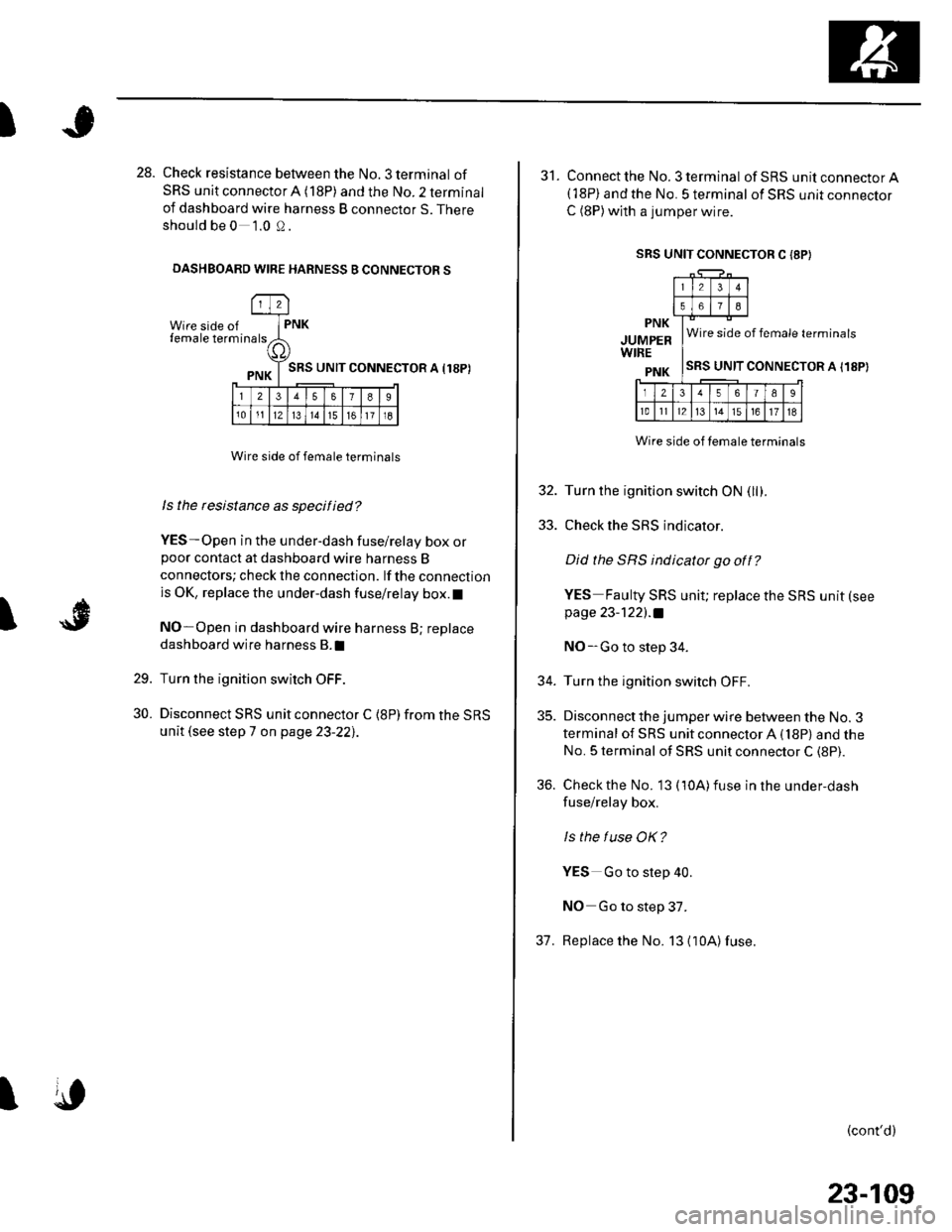
28. Check resistance between the No. 3 terminal of
SRS unit connector A (18P) and the No. 2 terminal
of dashboard wire harness B connector S. There
should be 0 1.0 0.
DASHBOARD WIRE HARNESS B CONNECTOR S
Wire side offemale term
l2
rna lsPNK
a,
PNK T SRS uNrr
l23578I
101112l314151611l8
CONNECTOR A I18P)
I
Wire side of female terminals
ls the rcsistance as specified?
YES-Open in the under-dash fuse/relay box orpoor contact at dashboard wire harness B
connectors; check the connection. lf the connection
is OK, replace the under-dash fuse/relay box.l
NO-Open in dashboard wire harness B; replace
dashboard wire harness B.I
Turn the ignition switch OFF.
Disconnect SRS unit connector C {8P) from the SRS
unit (see step 7 on page 23-22],.
29.
30.
I
SRS UNIT CONNECTOR C I8P}
31. Connect the No. 3 terminal ofSRS unitconnectorA(18P) and the No. 5 terminal of SRS unit connector
C (8P)with a jumper wire.
PNK
JUMPERWIRE
PNK
Wire side of female terminals
SRS UNIT CONNECTOR A I18P)
Wire side of temale terminals
32. Turn the ignition switch ON (llf .
33. Check the SRS indicator.
Did the SRS indicator go off?
YES Faulty SRS unit; replace the SRS unit (see
page 23-122l.a
NO-Go to step 34.
34. Turn the ignition switch OFF.
35. Disconnect the jumper wire between the No. 3
terminal of SRS unit connector A (18P) and the
No. 5 terminal of SRS unit connector C (8P).
36. Check the No. 13 (10A)fuse in the under,dash
fuse/relay box.
ls the f use OK?
YES Go to step 40.
NO Go to step 37.
37. Replace the No. 13 {10A)fuse.
(cont'd)
23-109
Page 1133 of 1139

Service Manual lndex
)s
NOTE: Referto the lollowing listto look up A/C Pressure Switch CircuitDTCS, symptoms, fuses, connectors, wire Troubleshooting ......... ...-.-....-...-.-.-....-..21-32 Bharnesses, specifications, maintenanceschedules, and general serviceinlormation:
DTC Troubleshooting Indexes
A/C Signal CircuitTroubleshooting.........................-...... 11-'133 Back-up Light SwitchTest .......................................................... 13'3A/F lAir Fuel Ratiol SensorABS/TCS Components ........................ 19-34 Replacement ....................................... 1 1-113 Back-up Li9ht3EPS Components ................................. '17-22 Circuit DiagramFueland Emissions11-i A-Dillar Corner Trim
ABS Indicator Circuit
Heating/Ventilation ................................ 21-9 Replacement ...............-.....-..............-.... 20,96 Ball Joint BootssRS ........................................................ 23-28Replacement ......
... 19-52 Ball Joints
22-75
18 16
Remova1.............-.......... . ...........18-10Symptom Troubleshooting Indexes TroubleshootingABS/TCSComponents........................ 19 35Cruise Control System ..........................4 38 ABS Modulator-contml UnitEPS Components ................................. 17-23 Bemoval/lnstallation ............................ 19-57 BettervFan Controls10,12
Accessory Powor Socket Front
Blowor Pow€r Transistor
.......22 50
Blower UnitRemoval/lnstallation ............................ 21-39
Fuel and Em issions .............................. 11-10 ABS/TCS ComoonentsHeating/Ventilation..............................21 10 Component Location Index ................. 19-30 Beverage Holder
SRS ........................................................ 23'30 CircuitDiaqram.......................... 19'42Blower MotorReplacement .....21 41
21-38
Power 0istribution ...............................22-46 TesVReplacement .............................. 22'149Under-dash Fuse/Relay Box ............... 22 45Under-hood Fuse/Belay Box ...............22 44 Accessory Power Sockets
Fuse/Relay lndexes
(to harness)
Connector and Wire Harness lndexesComponent Connectors
Circuit Oiagram .................................. 22-149
Air Cleaner......2214 Rep1acemen1.....................................11-162
Air MixControl MotorMeintenence section .................... Section 3 Replacement ......................................... 21'34 Brake CelipersTest......................21-34 Overhaul19-14,23Gene.al lnlormation section........ Section 1
21.57
Airbag. Driver's
Ahernator FR Signal CircuitTroubleshooting .... .........-..........11 134
AntennaReplacement
Inspection ............................................. 19-24Rep|acement................. .................... 19-25
Bieke Meder Cylinder
Irake Discs
A
Replacement ....................................... 23 1 'l3 Inspection .................... ................... 19-13,22Repair ...........-...................................... 23 1 16Brake Fluid Level SwitchAirbag. Front Passenger's TestBeplacement....................................... 23-1 14AIC Brake LightsComponent Location fndex ...................21-3 Altemator CircuitDiagram....................................22-74Description.....................................-....21'1'l Beplacement ................ ........................... 4 29CircuitDiagram....................................21-14 Overhaul .................................................4-30 Brake Lines and Hoses
19.10
A/C CompressolReplacement .......-...-............................. 21 -41
A/C Compr€ssor ClulchRep1acement......................................... 19-15.........22-103 Inspection ............................................. 19-16Inspecton........Overhaul ..........
A/C CondenserReplacement,.,
21-442l-49 Audio Unit
Replacement
Brake PadsRemoval/lnstallation .. ........................22-100 Inspection/Rep1acement................ 19-11,20A/C Compressor Clutch CircuitTroubleshooting ................................... 21-30 Audio Unit Connector Brake Pedal22101 Adjustment..............19,6ArfC Comoressor Relief ValvcReplacement ..........-...-.......................... 21-51 Audio/Entertainment
A/C Compr$sor Thermal Protector Circuit DiagramReplacement............-............................ 21-51
Component Location In dex .................22-9A Test .......-.............. 22-84Breke Pedal Posilion Switch
Brake Pedal Position Switch Signal Clrcuit11-137
.....21 52
A/C Condenser Fan CircuitTroubleshooting ................... . . . . . .....21-28
)s
Troubleshooting
(cont'd)