2003 HONDA CIVIC replace indicator relay
[x] Cancel search: replace indicator relayPage 645 of 1139

DTC 54: Main Relay Stuck OFF
1. Checkthe No.8 (20A) fuse in the under-hood fuse/
relay box, and reinstallthe fuse if it is OK.
ls the f use OK?
YES-Go to step 2.
NO Replace the fuse, and recheck.l
2. Disconnect the ABS control unit 31P connector.
3. l\4easure the voltage between the ABS control unit
connector terminal No. 18 and body ground.
ABS CONTROL UNIT 31P CONNECIOR
Wire side of female terminals
Is there battety voltage?
YES Replace the ABS modulator-control unit.l
NO-Repair open in the wire between the ABS
control unit and the under-hood fuse/relay box.I
DTC 61: lG2 Voltage
NOTE: Check the No. 11 (7.5A) fuse in the under-dash
fuse/relay box before troubleshooting.
1. Clear the DTC, then disconnect the Honda PGM
tesler.
2. Test drive the vehicle.
Doesthe ABS indicator come on and is DTC 61
ind icated ?
YES Go to step 3.
NO The system is OK at this time.l
3. Disconnect the ABS control unit3lPconnector.
4. Turn the ignition switch ON (ll).
5. Measure the voltage between the ABS control unit
31P connectorterminal No. 15 and body ground.
ABS CONTROL UNIT 31P CONNECTOR
ls there battery voltage?
YES Replace the ABS modulator-control unit.l
NO - Repair open in the wire between the ABS
control unit and the under-hood {use/relay box.l
Wire side of female terminals
19-51
Page 647 of 1139

8.
9.
Disconnect the gauge assembly connector A (22P).
Check for continuity between gauge assembly
connector A {22P) terminal No, 12 and body ground.
GAUGE ASSEMBLY CONNECTOR A (22P)
Wire side of female terminals
ls there continuity?
YES- Repair shon to body ground in the wire
between the gauge assembly and the ABS control
unit.l
NO Go to step 10.
Disconnect the gauge assembly connector B (22P).
Check for continuity between gauge assembly
connector B (22P) terminal No. 12 and body ground.
GAUGE ASSEMBLY CONNECTOR B (22PI
Wire side ol Iemale terminals
ls there continuity?
YES Check for loose terminals in the gauge
assembly connectors. lf the connectors are OK,
replace the gauge assembly.l
NO Repair open in the wire between the gauge
assembly and body ground (G501).1
'10.
11.
3.
ABS indicator does not go off
1. Checkthe No. 8 (20Alfuse in the under-hood fuse/
relay box, and reinstall the fuse if it is OK.
ls the fuse OK?
YES Go to step 2.
NO-Replace the fuse, and recheck. lf the fuse is
blown, check for a shon to body ground in this fuse
circuit. ll the circuit is OK, replace the ABS
modulator-control unit. I
Check the No. 11 (7.5A) fuse in the under-dash
fuse/relay box, and reinstall the fuse if it is OK.
ls the f use OK?
YES Go to step 3.
NO Replace the fuse, and recheck. If the fuse is
blown, check for a short to body ground in this fuse
circuit. lf the circuit is OK, replace the ABS
modulator-control unit. I
Disconnect the ABS control unit 31P connector.
Measure the voltage between terminal No. l8 and
body ground.
A8S CONTROL UNIT3lP CONNECTOR
ls there battery voltage?
YES-Go to step 5.
NO Repair open in the wire between the No. 8
(20A) fuse and the ABS control unit.l
(cont'd)
Wire side of female terminals
19-53
Page 895 of 1139

Gauges
2.
3.
Gauge Assembly Replacement
1.Remove the instrument panel (see page 20-59),
then remove the upper column cover {see page 17-
Place a clean shop towel (A) under the gauge
assembly to prevent scratching the steering
colum n or dash panel.
Remove the screws from the gauge assembly (B).
Disconnect the connectors (C), and remove thegauge assemDry.
Installthe gauge assembly in the reverse order of
removal.
Coolant Temperature Gauge
Troubleshooting
Before testing, check the No. I { 10A) fuse in the under-
hood fuse/relay box and the No. '10 (7.5A) fuse in the
under dash fuse/relay box.
1. Start the engine, and check the malfunction
indicator lamp (MlL).
Does the MIL come on?
YES- Troubleshoot the cause of the ECM DTC (see
page 1 1-57), and recheck.
NO-Go to step 2.
2. Check for a multiplex control unit DTC (see page
22,168).
ls a DTC ind icated?
YES Troubleshooting the cause of the multiplex
control unit DTC {see page 22-168), and recheck.
NO Go to step 3.
3. Do the communication line check with the self-
diagnosis procedure (see page 22-56).
ls the word "Error" indicated on the odo/ttip
d isplay ?
YES The gauge cannot receive the signal from the
multiplex control unit and the ECI\,4. Check for an
open in the WHT/GRN wire (gauge connector
terminal B 13). lf no open is found, go to step 5.
NO Go to step 4.
4. Do the gauge drive circuit check with the self-
diagnosis procedure (see page 22-56).
Does the temperature gauge needle sweep lrom
the minimum position to the maximum, then tetutn
to the minimum position?
YES Go to step 5.
NO Replace the gauge assembly.l
5. Substitute a known-good ECM and recheck.
Did the symptom/ ind ication go away?
YES Replace the ECM.
NO Substitute a known good gauge assembly. lf
the symptom/indication goes away, replace thegauge assembly.l
4.
22-64
Page 901 of 1139

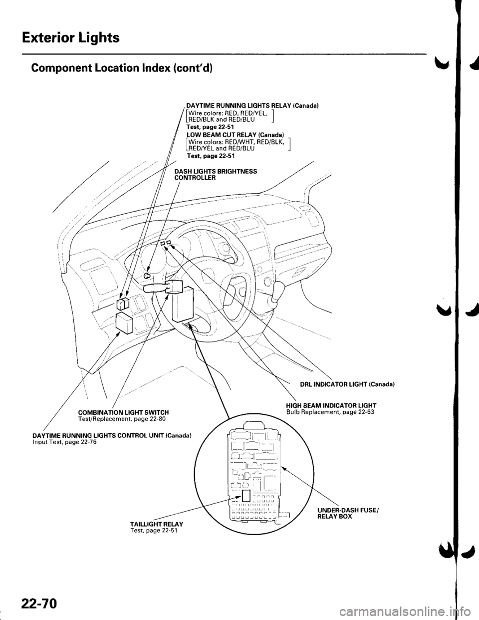
Exterior Lights
Component Location Index (cont'dl!
DAYTIME RUNNING LIGHTS RELAY {Canadal[Wire colors: RED, REDryEL, ILRED/BLK and RED/BLU ITest, page 22-51
_LOW BEAM CUTRELAY {Canadal _Wire colorsr REDMHT, RED/BLK, ILREDryEL and RED/BLU ITest, page 22-51
DASH LIGHTS BRIGHTNESSCONTROLLER
/
COMBINATION LIGHT SWITCHTesVReplacement, page 22-80
oAYTIME RUNNING LIGHTS CONTROL UNIT lcanada)Input Test, page 22-76
DRL INDICATOR LIGHT {Canadal
HIGH BEAM INDICATOR LIGHTBulb Replacement, page 22-63
UNDER.DASH FUSE/RELAY BOX
:' --,': - '
' i,-'-'l
..i \
I t- -
22-70
Page 908 of 1139

4. Make these input tests at the connector,
.lfanytestindicatesaproblem,findandcorrectthecause,thenrecheckthesystem.
. lf all the input tests prove OK, the control unit must be faulty. Replace it.
CavityWireTest conditionTest: Desired resultPossible cause if result is not obtained2R E D/BLUUnder all
conditions
Check for voltage to ground:
There should be battery voltage.
Blown No. 14 (40A) fuse in the
under-hood fuse/relay box
Blown No. 3 {10A)fuse in the
under-dash fuse/relay box
An open in the wire12YE L/RE Dlgnition switch
oN (r)Check for voltage to ground:
There should be battery voltage.
Blown No. l2 (7.5A)fuse in the
under-dash fuse/relay box
An open in the wire
BLKUnder all
conditions
Check for continuity to ground:
There should be continuitv.
. Poor ground {G50'1). An oDen in the wire7BLKUnder all
conditions
Check for continuity to ground:
There should be continuitv.
. Poor ground (G501)
' An open in the wire
10REDI/ELCombination
light switch ON/ =f\
Check for voltage to ground:
There should be battery voltage.
Blown No. 15 (15A) fuse in the
under-hood fuse/relay box
Faulty headlight relay 2
Faulty combination light switch
An open in the wire
1RED/B LUCombination
light switch ON
{iD), and
dimmer switch
in HIGH
Connect a jumper wire between
No.3 and No. 1 terminals.
Both headlights (HIGH) and
h igh beam indicator light
should come on.
Blown bulb
Faulty low beam cut relay
Faulty combination light switch
Poor ground (G50'l )
An open in the wire'11
3
RED/BLK
GRN/BLK
Combination
light switch ON(iD), and
dimmer switch
in HIGH
Com bination
light switch ON(iD), and
dimmer switch
in HIGH
Connect a jumper wire between
No. 5 and No. 11 terminals.
Right headlight (HIGH) should
come on.
Check for continulty to ground
There should be continuity.
. Blown bulb. Faulty combination light switch. Poor ground (G 50'1 ). An open in the wire
. Faulty combination light switch. Poor grou nd {G501). An open in the wire
5
6GRN/ORNParking brake
lever oulled
Check for continuity to ground:
There should be continuitv.
Faulty parking brake switch
An open in the wire
8BLU/REDCombination
light switch OFF
Check for voltage to ground:
There should be battery voltage.
Faulty headlight relays
Short to ground
An ooen in the wire
WHT/BLUlgnition switch
oN 0r)
Attach to ground:
The DRL indicator light should
come on.
. Blown No. 10 (7.5A) fuse in the
under-dash fuse/relay box. Faulty DRL indicator. An ooen in the wire
t5G RN/REDlgnition switch
oN (||)Attach to ground:
The brake system light should
come on.
Faulty brake system indicator
An open in the wire
22-77
Page 916 of 1139

Turn Signal/Hazard Flasher
Component Location Index
COMBINATION LIGHT/TURN SIGNAL SWITCHTest, page 22-80Beplacement, page 22-80
TURN SIGNAL INDICATOR LIGHTS(ln the gauge assembly)Bulb Replacement, page 22'63
HAZARD WARNING SWITCHTest, page 22-88Replacement, page 22-88
TURN SIGNAL/HAZARD RELAYInput Test, page 22-87
UNDER.DASH FUSE/RELAY BOX
22-85
Page 1007 of 1139

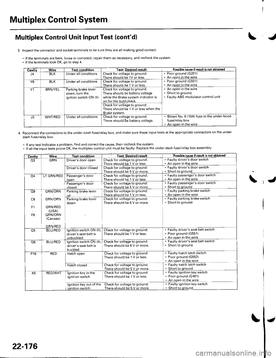
Multiplex Control System
Multiplex Control Unit lnput Test (cont'd)
3. Inspect the connector and socket terminals to be sure they are all making good contact
.lftheterminalsarebent,looseorcorroded,repairthemasnecessary,andrecheckthesystem. llthe terminals look OK, go to step 4.
4. Reconnectthe connectorstothe under dash fuserelay box, and make surethese inputtests atthe appropriate connectors on lhe under-
dash fuse/relav box.
. lf any test indicates a problem, {ind and correct the cause, then recheck the system. lf allthe input tests prove OK, the multiplex control unit must be faulty. Replace the under_dash fuse/relay box assembly
CavitvWireTest conditionTest: Desired .esult r Possible cause if resullE qS!q!!e!!ed
J4BLK[J nder all conditionsCheck {or voltage 1o ground:Therc sholl.l he 1V or lessPoor ground (G20'l)An ooen in the wire
Y6BLKlJnder all conditionsCheck for voltage to ground:There should bc 1 V or less.Poor ground 1G501)An ooen in the wire
Y1BFNryELParking brake leverdown, turn theigntion switch ON (ll)
Check for voltage to ground:There should be battery voltagewhile the Brake system indicator ison forthe buld check.
An open in the wireShortto groundFaulty ABS modulatorcontrol unit
Check for voltage to ground:There should be 1V or less when the
J2WHT/REDUnder allconditionsCheck for voltage to groundiThere should be baftery voltage.Blown No.9 (10A)fuse in the under'hoodfuse/relay boxAn oncn in rhc wire
CavitvTest conditionTesi: Oesired resultPossible cause ifresult is notobtained
o3GRNDriver's door openCheck for voltage to ground:There should be 1 V or less-Faulty driver's door switchAn ooen in the wire
Driver's door closedCheck for voltage to ground:There should be 5 V or more.Faulty driver's door switchShort to qround
O4LT GRN/REDPassenger's doorCheck .for voltage 10 ground:There should be 1 V or less.Faulty passenger's door switchAn ooen inthewire
Passenger's doorCheck for voltage to ground:There should be 5 V or more.Faulty passenger's door switchShort to oround
osI]l.l
4.,
F1
F8
GRN/ORN
GRN/ORN
GRN/RED(USA)GRN/ORN(Canada)
Parking brake leverCheck for voltage to groLrnd:There shorl.l be 1 V or less.Faulty parking brake switch. An ooen in thewireCheck for voltage to ground:There should be 5 V or more.
. Faulty parking brake switchShortto ground
o5BLU/REDlgnition switch ON (ll),
driver's seat belt isCheck for voltage to ground:There should be 1V or less.Faulty driver's seat belt switchPoorground (G551)An oDen in the wire
Q6BLU/REDlgnition switch ON (ll)
driver's seat belt isbuckled.
Check {or voltage to ground:There should be 6 V or more.Faulty driver's seat belt switchShortto ground
P18RED
H",=
Check for voltage to ground:There sho0ld be 1V or less-
f -9*:li:'^:**:':s*:*
Faulty hatch latch swrtchPoor ground (G552)An open in the wireFaulty hatch latch switch
X5lgnirion key in the Check for voliage to gtound:ignit on switch Thpre should be I V or lcss
lgnrtron kev our o{ the Check for vollage to ground:
. Faulty ignition key switch. Poor ground (G401). An open in the wire
I : [11y.'::i':::1"' **6
\
22-176
Page 1113 of 1139

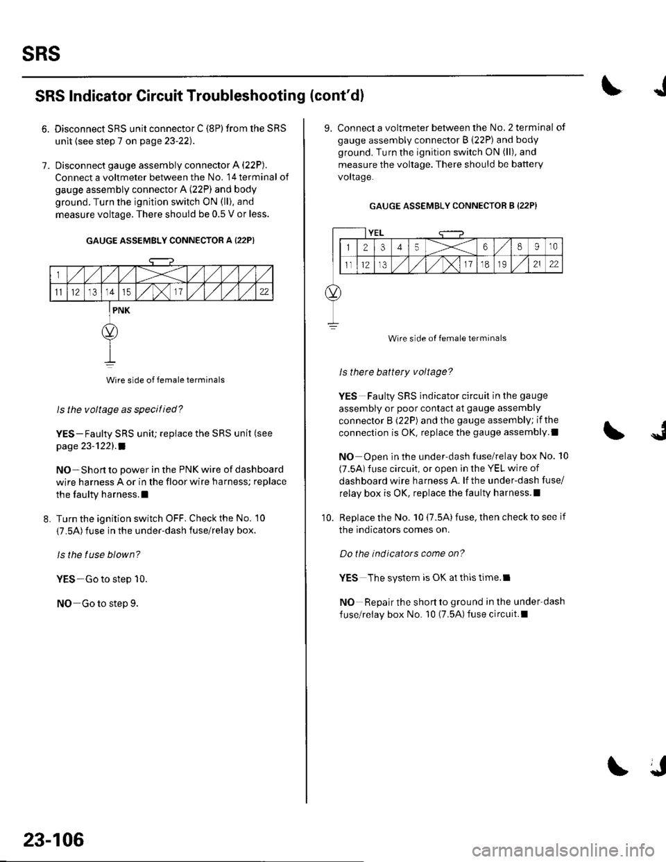
sRs
6.
SRS Indicator Circuit Troubleshooting (cont'dl
7.
Disconnect SRS unit connector C (8P) from the SRS
unit {see step 7 on page 23-22).
Disconnect gauge assembly connector A (22P).
Connect a voltmeter between the No, l4terminal of
gauge assembly connector A (22P) and body
ground. Turn the ignition switch ON (ll), and
measure voltage. There should be 0.5 V or less.
GAUGE ASSEMBLY CONNECTOR A {22P)
Wire side of female terminals
ls the voltage as specitied?
YES-Faulty SRS unit; replace the SRS unit (see
page 23-'l22l.a
NO-Short to power in the PNK wire of dashboard
wire harness A or in the floor wire harness; replace
the faulty harness.l
L Turn the ignition switch OFF. Check the No. 10
{7.5A)fuse in the under-dash fuse/relay box.
ls the tuse blown?
YES-Go to step 10.
NO Go to step 9.
23-106
J
9. Connect a voltmeter between the No.2 terminal of
gauge assembly connector B (22P) and body
ground. Turn the ignition switch ON (ll), and
measure the voltage. There should be battery
voltaqe.
GAUGE ASSEMBLY CONNECTOR B (22P}
YEL
12345X68910
ll12,/ ,/,/x11o2122
Wire side of female terminals
ls therc battery voltage?
YES Faulty SRS indicator circuit in the gauge
assembly or poor contact at gauge assembly
connector B (22P) and the gauge assembly; if the
connection is OK, replace the gauge assembly.l
NO Open in the under-dash fuse/relay box No. 10
(7.5A) fuse circuit, or open in the YEL wire of
dashboard wire harness A. lf the under-dash fuse/
relay box is OK, replace lhe faulty harness.l
Replace the No. 10 (7.5A) fuse, then check to see if
the indicators comes on.
Do the indicators come on?
YES The system is OK at thls time.l
NO Repair the short to ground in the under-dash
fuse/relay box No. 10 (7.5A)fuse circuit.l
10.