Page 49 of 1139

Starting System
Starter Overhaul (cont'dl
Planetary Gear Inspection
16. Check the planetary gears (A) and ring gear {B).Replace them if they are worn or damaged.
Overrunning Cluich Inspection
17. Slide the overrunning clutch along the shaft.
Replace it if it does not slide smoothly.
18. Rotate the overrunning clutch (A) both ways.
Does it lock in one direction and rotate smoothly inreverse? lf it does not lock in either direction or it
locks in both directions, replace it.
lf the starter drive gear (B) is worn or damaged,
replace the overrunning clutch assembly; the gear
is not available separately.
Check the condition of the flywheel ring gear.
Replace it if the starter drive gear teeth are
oamageo.
19.
4-14
i.-
Starter Reassembly
20, Pry back each brush spring with a screwdriver, thenposition the brush about halfway out of its holder,
and release the spring to hold it there.
NOTE: To seatthe new brushes. slip a strip of #5OO
or # 600 sandpaper. with the grit side out, be&veen
the commutator and each brush, and smoothly
rotate the armature. The contact surface of the
brushes will be sanded to the same contour as the
commutator.
21lnstallthe armature in the housing, and installthe
brush holder. Next, pry back each brush spring
again, and push the brush down until it seats
against the commutator, then release the spring
against the end of the brush.
s
Install the starter end cover to retain the brush
holder.
Page 52 of 1139

lgnition Timing Inspection
1.
4.
5.
Connect the Honda PGM Tester to the data link
connector (DTC), and check for DTC'S. lf a DTC is
present, diagnose and repair the cause before
inspecting the ignition timing.
Startthe engine. Hold the engine at 3,000 rpm with
no load (in Neutral) until the radiator fan comes on,
then let it idle.
Check the idle speed (see page 11-138).
Follow the tester's prompts in the "SCS" menu
{see the tester operator's manual),
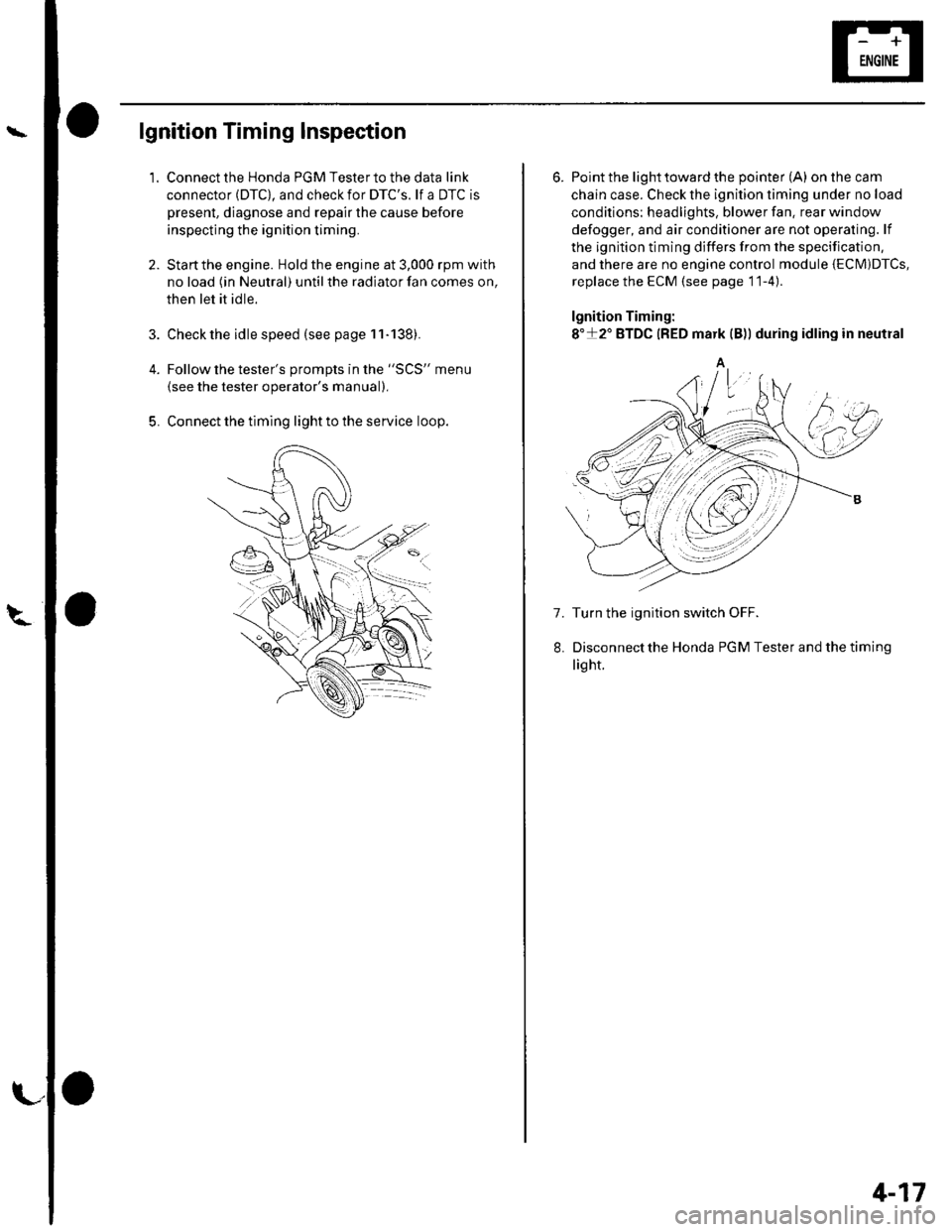
Connect the timing light to the service loop.
o
6. Point the light toward the pointer (A) on the cam
chain case. Check the ignition timing under no load
conditions: headlights, blower fan. rear window
defogger, and air conditioner are not operaling. lf
the ignition timing differs from the specification,
and there are no engine control module {ECM)DTcs,
replace the ECM (see page 11-4)
lgnition Timing:
8"+2" BTDC {RED mark {B)) during idling in neutral
A
7. Turn the ignition switch OFF.
Disconnectthe Honda PGM Tester and thetiming
light.
4-17
Page 57 of 1139

Gharging System
Charging Circuit Troubleshooting
lf the charging system indicator does not come on or
does not go off, or the battery is dead or low, test these
items in the order listed below:
Battery (see page 22-50)
Charging system indicator
Alternator and regulator circuit
Alternator control system
Charging System Indicator Test
1. Turn the ignition switch ON {ll).
Does the chatging system indicator come on?
YES Go to step 2.
NO Go to step 3.
2. Start the engine.
Does the charging system indicator go off?
YES-Charging system indicator circuit is OK. Go
to the Alternator and Regulator circuit Test. t
NO-Go to step 3.
3. Turn the ignition switch OFF.
4. Troubleshoot the multiplex control system (see
page 22 172).
ls the multiplex control system OK?
YES Go to step 5.
NO Check the multiplex control system as
indicated by the diagnostic trouble code (DTC) (see
step 8 on page 22-172).1
5. Disconnect the engine wire harness 6P connector
from the starter sub harness 6P connector.
4-22
\"4
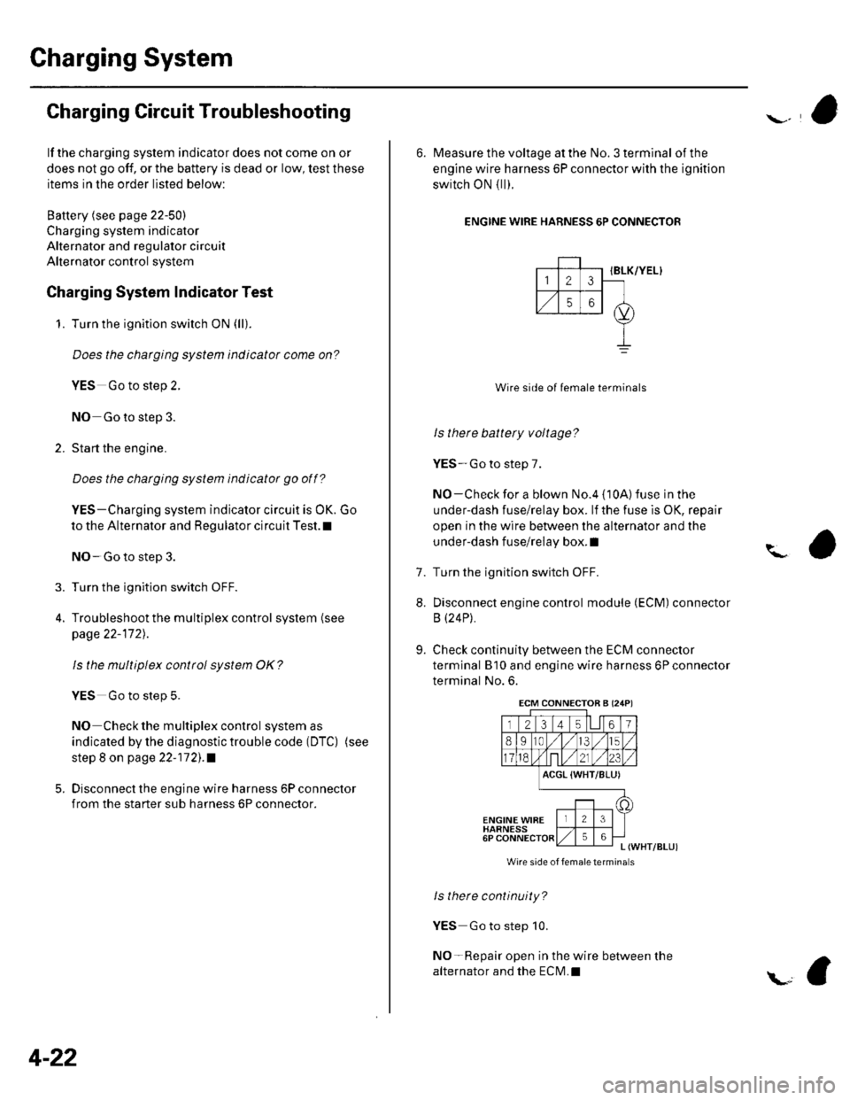
6. Measure the voltage at the No. 3 terminal of the
engine wire harness 6P connector with the ignition
switch ON { ll).
ENGINE WIRE HARNESS 6P CONNECTOR
IBLK/YEL}
Wire side of female terminals
ls there battery voltage?
YES-Go to step 7.
NO-Check for a blown No.4 {10A) fuse in the
under-dash fuse/relay box. lf the fuse is OK, repair
open in the wire between the alternator and the
under-dash fuse/relay box. I
Turn the ignition switch OFF.
Disconnect engine control module (ECM) connector
B (24P).
Check continuity between the ECM connector
terminal B'10 and engine wire harness 6P connector
terminal No. 6.
?
7.
8.
9.
ACGL {WHT/BLU)
ENGINE WIBEHARNESS6PL (WHT/BLUI
Wire side of femaletermina s
ls there continuity?
YES Go to step 10.
NO-Repair open in the wire between the
alternator and the ECN4.I
ECM CONNECTOB A (24P)
Page 58 of 1139
'10. Check continuity between the ECM connector
terminal 810 and body ground.
ECM CONNECTOR S I24PI
23 t4 t567
8I10,/1,/315
118,Nnt,/2123
ACGL (WHT/BLUI
t1'
Wire side ol female terminals
ls there continuity?
YES- Repair short to ground in the wire between
the ECM and the engine wire harness 6P connector.
t
NO-Go to alternator and regulator test.
Alternator and Regulator Circuit Test
1. Be sure the battery is sufficiently charged and in
good condition {see page 22-50), and the
connections at the fuse box and alternator are
clean and tight.
2. Raise the hoist to full height.
3. Hook up the ammeter, 0 400 A, to the starter
sub harness.
Lower the hoist.
Hook up the voltmeter, 0 20 V (accurate within
0.1V),toT101.
(cont'd)
4-23
Page 59 of 1139

Gharging System
Charging Circuit Troubleshooting (cont'd)
6. Start the engine. Hold the engine at 3,000 rpm with
no load (in Neutral) until the radiator fan comes on,
then let it idle.
7. Raise the engine speed to 2,000 rpm, and hold it
there.
8. Turn the headlights (high beam) on, and measure
voltage at the under-hood fuse/relay box terminal.
ls the voltage between 13.9 and 15.1 v?
YES-Go to step 9.
NO Repair or replace the alternator components
(see page 4-30).1
9. Read the amperage at '13.5 V.
NOTE: Adjust the voltage by turning the blower
motor, rear window defogger, brake lights. etc. ON.
ls the amperage 604 ot morc?
YES-Alternator/regulator operation is OK. I
NO Repair or replace the alternator components(see page 4-30).1
4-24
\,
Alternator Control System Test
NOTE: After troubleshooting, perform the engine
control module (ECM) idle learn procedure (see page
11-139).
1 . Check for proper operation of the electrical load
detector (ELD) by checking the malfunction
indicator lamp (MlL) (see page 1 l-3). lf a DTC is
present, diagnose and repair the cause before
continuing with this test.
2. Disconnect the engine wire harness 6P connector
from the starter sub harness 6P connector.
3. Start the engine, and turn the headlights (high
beam) ON,
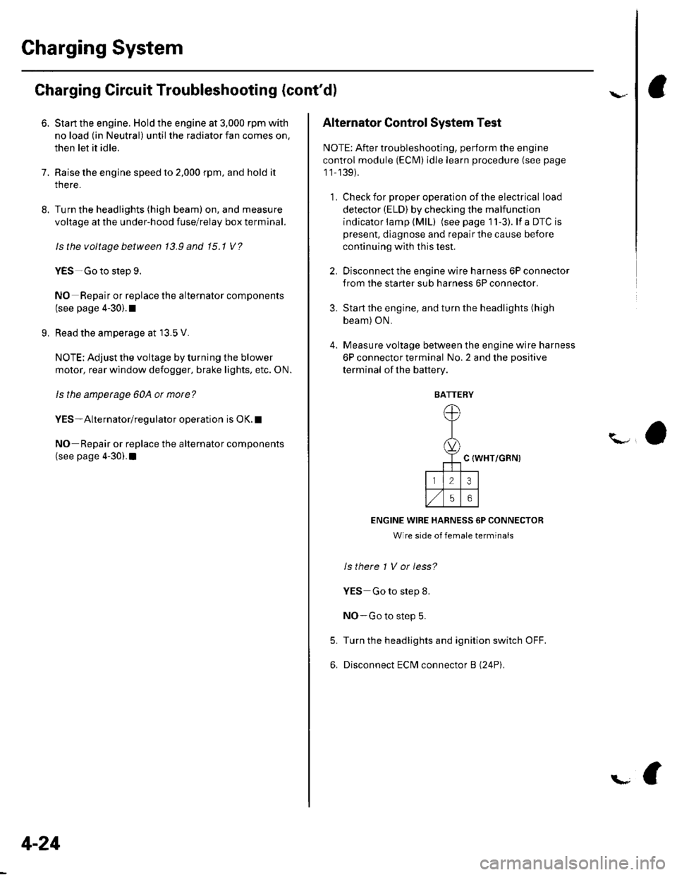
4. Measure voltage between the engine wire harness
6P connector terminal No. 2 and the positive
terminal of lhe battery.
C {WHT/GRN)
ENGINE WIRE HARNESS 6P CONNECTOR
Wire side of female terminals
ls there 1 V or less?
YES Go to step 8.
NO-Go to step 5.
Turn the headlights and ignition switch OFF.
Disconnect ECM connector B (24P).
5.
6.
BATTERY
Page 60 of 1139

\
L
7, Check for continuity between ECM connector
terminal 818 and body ground.
ECM CONNECTOR B {24PI
123 t4 t561
8910,/1,/35
11ont,/2123
ACGC {WHT/GRN}
o
Wire side ot female terminals
9.
ls there continuity?
YES-Repair short to ground in the wire between
the alternator and the ECM.I
NO-Check that the terminals are firmly seated at
the ECM connector B. lf OK, substitute a known-
good ECM, and recheck (see page 11-6).
lf prescribed voltage is now available. replace the
original ECM,I
Turn the headlights and ignition switch OFF.
Disconnect ECM connector B (24P).
10. Check for continuity between ECM connector
terminal 818 and engine wire harness 6P connector
terminal No.2.
ACGC (WHT/GRN)
ECM CONNECTOR B l2,lPI
12314l5lll67
8910t.)15
11on2123
oC (WHT/GRN)
23
56
ENGINE WIRE HARNESS 6P CONNECTOR
Wire side oI lemale terminals
ls therc continuity?
YES Repair or replace the starter subharness or
the alternator (see page 4-30).I
NO Repair open in the wire between the
alternator and the ECM.I
4-25
Page 62 of 1139

\Drive Belt Auto-tensioner Inspection
1.Check whether there is a change in the position of
the auto-tensioner indicator before starting the
engine and after starting the engine. lf there is a
change in the position, replace the auto-tensioner.
3.
Check for abnormal noise from the tensioner pulley.
lf abnormal noise is heard, replace the tensioner
pulley.
Remove the drive belt (see page 4-26).
lMove the auto-tensioner within its limit with the
belt tension release tool in the direction shown.
Check that the tensioner moves smoothly and
without any abnormal noise. lf the tensioner does
not move smoothly or there is abnormal noise,
replace the auto-tensioner.
7.
8.
Remove the auto-tensioner (see page 4-28).
Install the tensioner pulley.
Clamp the auto-tensioner (A) by using two 8 mm
bolts (B) and a vise (C) as shown. Do not clamp the
auto-tensioner itself .
Set the torque wrench (D) on the pulley bolt.
Align the indicator {E) on the tensioner base with
center mark (F) on the tensioner arm by using the
torque wrench, and measure the torque. lf the
torque value is out of specification, replace the
auto-tensioner,
NOTE; lf the indicator exceeds the center mark,
recheck the torque.
Auto-tensioner spring torque:
26.5-36.3 N.m 12.7-3.7 kg.m, 19.5-26.8lbt.ft)
9.
4-27
Page 72 of 1139
Circuit Diagram
' No.aloAl USAnod.lNo.20 itoAl C.md! modrlUISEF NOOD fUS'/iILAY IOX
-to ots BU/YIL
lcl H0Tii0llilllmdSTARTlllll
1 Honilsffroi
CTuICII PEDALP0sm0 swtrct
26 1113cnu6E coNTnoL uNtT l0
4-37