2003 HONDA CIVIC wiper control unit test
[x] Cancel search: wiper control unit testPage 832 of 1139

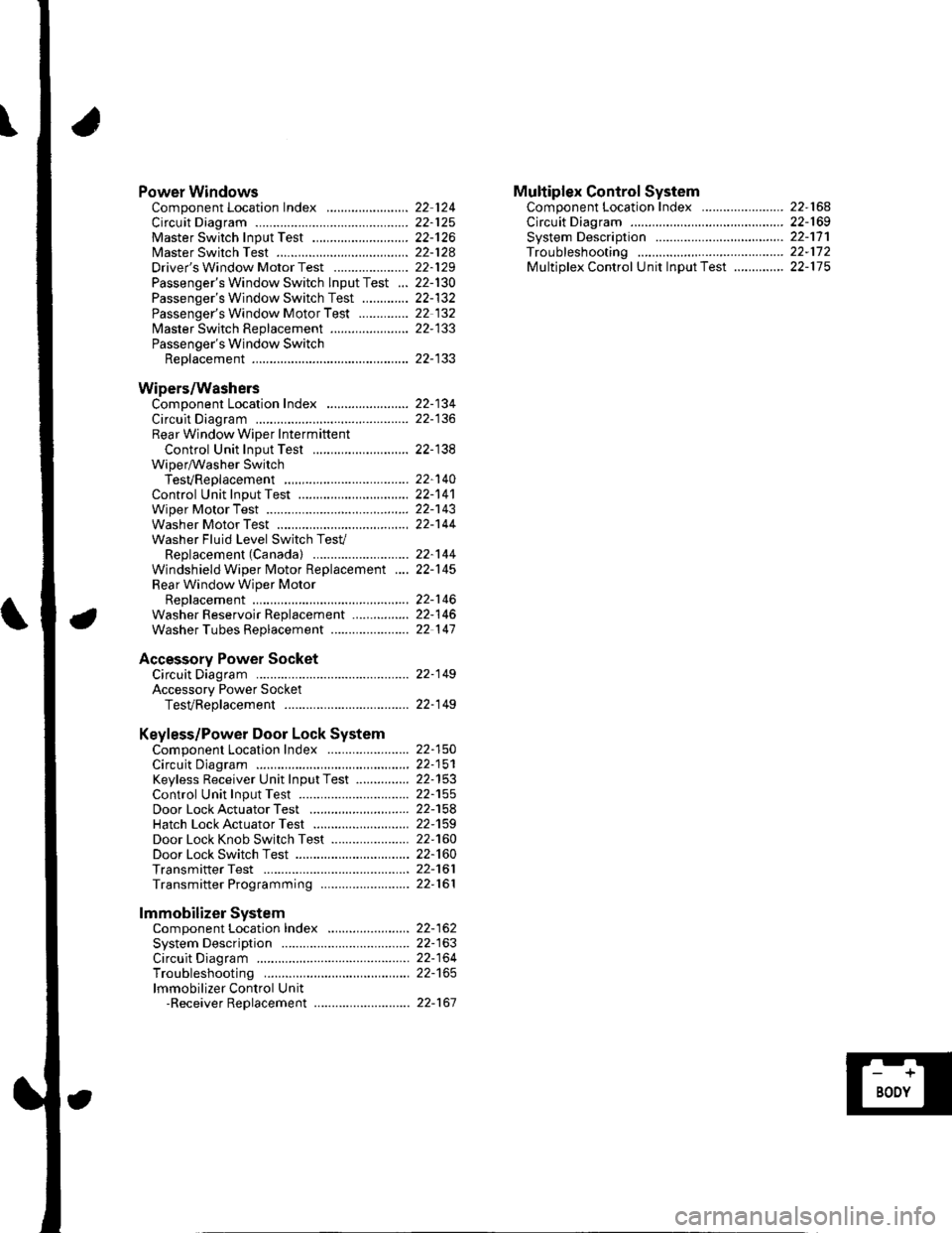
Power WindowsComponent Location Index ..........
circuit Diagram . .. ............... .........:.::::.::::.:Master Switch Input Test ...........................Master Switch TestDriver's Window Motor Test .....................
Passenger's Window Switch lnput Test ...Passenger's Window Switch Test .............
Passenger's Window Motor Test ..............
lMaster Switch Replacement ......................
Passenger's Window SwitchReplacement
Wipers/WashersComponent Location Index .......................
Circuit DiagramRear Window Wiper Intermiftent
Control Unit Input Test ...........................Wiper/Washer SwitchTesVReplacementControl Unit Input Test ...............................Wiper Motor Test
Washer Motor TestWasher Fluid Level Switch TesV
Replacement (Canadal ..........................
Windshield Wiper Motor Replacement ....
Rear Window Wiper MotorReplacementWasher Reservoir Replacement ................
Washer Tubes Beplacement ......................
Accessory Power SocketCircuit Diagram ......... 22-149
Accessory Power Socket
TesVReplacement ................................... 22-1 49
Keyless/Power Door Lock System
Component Location Index ....................... 22-150
Circuit Diagram ......... 22-151Keyless Receiver Unit InputTest ............... 22-153
Control Unit Input Test ............................... 22-155
Door LockActuatorTest .........,.......,..,.,..... 22-158Hatch LockActuatorTest ........................... 22-159
Door Lock Knob Switch Test ...................... 22-160
Door Lock Switch Test ................................ 22-160
Transmitter Test ....... 22-161
Transmitter Programming ......................... 22-161
Multiplex Control SystemComponent Location Index ...........
circuit Diagram ...... ........................::.:..:.::.:
Svstem DescriDtionTroubleshootingMultiolex Control Unit InDut Test .............
22 12422-12522-12622-12822-129
22- t30
22-13222 13222-133
22-133
22-134
22-138
22-14022-14122-14322-144
22-14422-145
22-14622-14622 147
22,16422-16922-17'l22,11222-175
lmmobilizer Systemcomponent Location Index ...........
System Description ....... ............. ..:..:..:.:...
Circuit DiagramTroubleshootinglmmobilizer Control Unit-Receiver Replacement ...........................
22-16222-16322-164
22-167
Page 851 of 1139

Connectors and Harnesses
Engine Compartment Wire Harness (Left branch)
AirJuel (A,,/F) ratio sensorBrake fluid level switchCondenser fan motorCruise control actuatorELD unitFog light connectorLeft front ABS wheel sensorLeft front airbag sensorLeft front parking lightLeft front side marker lightLeft lrontturn signal lightLeft headlightLeft hornRadiator fan motorRadiator fan switchSecondary heated oxygen (SHO2S)
Test tachometer connectorWindshield wiper motorUnder'hood fuse/relay boxconnector A {see page 22-44)Under-hood f use/relay boxconnector B (see page 22-44)Under hood fuse/relay boxconnector C (see page 22-44)Under hood fuse/relay boxconnector D (see page 22 44)Under-hood fuse/relay box
Front of engine companmentLeft side of engine compartmentLeft side of engine compartmentLeft side o{ engine compartmentFront of engine compartmentUnder right side of cowl coverUnder'hood f use/relay boxLeft side of engine compartmentLeft side of engine companmentBehind left side of front bumperBehind left headlightBehind left side of front bumperEehind left headlightBehind left headlightBehind front bumperLeft side of engine compartmentFront of engine compartmentLeft side of engine compartment
Left side of engine companmentL.Jnder left side of cowl coverL.Jnder hood fuse/relay box
L.Jnder hood fuse/relay box
L.Jnder'hood f use/relay box
underhood fuse/relay box
Under-hood fuse/relay box
24222
2519
12
17
13202123
3
117
I
10
5
6
l2
2243,l
222223l224
252
5
12
Connector to Harness Index (cont'dl
\
22-20
Page 965 of 1139

Wipers/Washers
Component Location Index
WINDSHIELD WIPER MOTORTest, page 22-'143Replacement, page 22-145
WINDSHIELD WIPER ARMS and LINKAGEReplacement, page 22-'145
WIPER/WASHER SWITCHTest, page 22-140Replacement,page 22 140
UNDER.DASHFUSE/RELAY BOX
INTERMITTENT WIPER CIRCUITlln the multiplex control unit)Input Test, page 22-138
22-134
Page 966 of 1139

REAR WINOOW WASHER MOTORTest, page 22-144Replacement, page 22 146
WINDSHIELD WASHER MOTORfesl, page 22 144Beplacement, page 22-146
WASHER TUBESReplacement, page 22-147
CONDENSERCapacityTest, page 22 107
BEAR WINDOW WIPER ARMReplacement, page 22 146
WASHER RESERVOIBReplacement, page 22'146
WASHER FLUID LEVEL SWITCH {Canada)TesI, page22-144Replacement, page 22-144
REAR WINDOW WIPER INTERMITTENTCONTROL UNITInput Test, page 22'138
REAR WINDOW WIPER MOTORf e$, page 22-143Replacement, page 22 146
22-135
Page 969 of 1139

Wipers/Washers
1.
2.
Rear Window Wiper Intermittent Gontrol Unit Input Test
Remove the right rear side trim panel {see page 20-51).
Disconnect the 20P connector (A) from the rear window.wiDer intermittent control unit (B).
Inspect the connector and socket terminals to be sure they are all making good contact.
. lf the terminals are bent, loose orcorroded, repairthem as necessary, and recheckthe system.. lf the terminals look OK, go to step 4.
Wire side of female terminals
LTGRN/REO WHT/RED LT GRNWHT/RED
LT GRN/BLK
22-138
Page 970 of 1139

\
4. With the connector still disconnected, makethese input tests at the con necrors.
.lfanytestindicatesaproblem,findandcorrectthecause,thenrecheckthesystem.
' lf all the input tests prove OK, the control unit must be faultv. Replace it.
CavitvWireTesl conditionTest: Desired resultPossible cause if result is not obtainedGRNlgnition switch ON
flr)
Check for voltage to ground:
There should be battery
voltaqe.
. Blown No.9 (10A)fuse in the
under-dash fuse/relay box. An open in the wire10BLKUnder all
conditions
Check for continuity to
grouno:
There should be continuitv.
Poor ground (G553)
An open in the wire
6WHT/REDlgnition switch ON(ll) and rear
window washer
switch ON
Check for voltage to ground:
There should be battery
vortage.
Blown No.9 (10A) fuse in the
under-dash fuse/relay box
Faulty rear wlndow wiper/
washer switch
An open in the wire4LT GRN/
RED
lgnition switch ON(ll) and rear
window wiper
switch ON
Attach to groundl
The rear window wiper motor
should run.
LT GRNlgnition switch ON
flr)
Attach to ground:
The rear window wiper motor
should run.
Blown No. 9 (10A)fuse in the
under-dash fuse/relay box
Faulty rear window wiper motor
An open in the wire20LT GRN/
BLK
lgnition switch ON(ll)Check for voltage to ground:
There should be battery
voltage.
Blown No.9 (10A) fuse in the
under-dash fuse/relay box
Faulty rear window wiper motor
An oDen in the wire
22-139
Page 973 of 1139

Wipers/Washers
Control Unit Input Test (cont'dl
5. Reconnect the connectors, and make these input tests at the connector.
.lfanytestindicatesaproblem,findandcorrectthecause,thenrecheckthesystem.
.lfalltheinputtestsproveOK,themultiplexcontrol unit must be faulty. Replace the under-dash fuse/relay box
assembly.
CavityWireTest conditionTest: Desired resultPossible cause if result is not obtained
J4BLKU nder all
conditlons
Check for voltage to ground: . Poor ground (G501)
There should be 1V or less. . AnoDeninthewire
Y6BLKU nder all
conditions
Check for voltage to ground: . Poor ground (G502)
There should be 1 V or less. . An oDen in the wire
BIWHTiBLUlgnition switch ON
{ll) and washer
switch ON
Check for voltage to ground:
There should be battery
vortage.
Blown No. 20 (20A) fuse in the
under-dash fuse/relay box
Faulty wiper/washer switch
An open in the wire
E'0BLU/REDlgnition switch ON
(ll) and wiper
switch OFF (wiper
motor stopped)
Check for voltage to ground:
There should be battery
voltage.
Blown No. 20 (20A) fuse in the
under-dash fuse/relay box
Faulty wiper/washer switch
Faulty windshield wiper motor
An open in the wire
G7BLUA/VHTlgnition switch ON(ll) and wipers in
park position
Check for voltage to ground:
There should be battery
voltage.
Blown No.20 (20A)fuse in the
under-dash fuse/relay box
Faulty windshield wiper motor
An ooen in the wire
x1BLU/BLKlgnition switch ON(ll) and wiper
switch in INT
Check for voltage to ground:
There should be battery
voltage.
Blown No.20 (20A)fuse in the
under-dash fuse/relay box
Faulty wiper/washer switch
An oDen in the wire
\J
\J
L
22-142
J
Page 1137 of 1139

)
Low Fuel lndicatorTest.....................11-158Moonroof Drain Channel SliderReplacement......................................... 20'44
Moonroof FrameRep1acement,,,,,,,,,,.,.,.,.,.,.,.,,,,,,............ 20 42
MoonroolGlassAdiustment ........................................... 20-37Rep1acement......................................... 20 37
Moonroot Limit SwitchAdjustment ........................................-.- 20 46Test ...................................................... 22 113
Moonrool MotorReplacement....-.................................... 2D-41
Oil Pressure SwitchTest ................-.-........-................................ 8-4Replacement.........-................................. 8-16
Oil Pump, EngineOverhau1 ................................................... 8-8
Oil, EngineReplacement...-................-.-...................... 8-5
OPDS UnitReplacement....................................... 23- 124
Outside Mirror HoldersBeplacement......................................... 20-15
Outside Power Mirror ActuatorsTest ...................................................... 22-117Bepf acement..-.................................... 22-1 14
Outside Power Mirror SwitchTest ..-................................................... 22-111
Outsid€ Power MirrorsReplacement............................ ... .. . . . 20-15Component Location lndex .............. 22- 114Circuit Diagram .................................. 22-115Test -..................................................... 22-116
Lower ArmsRemoval/1nsta11ation............................ 18 19
Lubrication SystemComponent Location Index..................... 8-3Test............................................................ 8 4
M
M/TAssemblyRemoval.......... 13-4 Test...................... 22-1 12lnstallation............. 13-8
.........21,35
Disassembly ......................................... 13-14Resassembly .. ... ................. 13-46
M/TChange Leverlnspection ............................................. 13-19Disassembly 8eassemb1y ................... 13-20
M/T Countershaft AssemblyInspection ....................................... 13 31, 33Disassemb1y ......................................... 13-32Resassemb|y ........................................ 13-34
M/T DifferentialComponentLocation Index................. 13-52Adiuslment ........................................... 13-56
M/T Maifthaft Assembly1nspection ... ................................... 13-23, 26Disassembly ......................................... 13 25Resassembly ........................................ 13 28Adjustment ........................................... 13-43
M/T Reverse Shift ForkInspection .................... ........................ l3 19
M/T Shift LevelReplacement......................................... 13-51
Mainshaft BearingsReplacement....,.................................... 13 41
MairtenancelSee section 3)
MILHow to Informatron ............................. 1 1.46
MIL CircuitTroubleshooting .......... .- . . . . ......... 11 97
MirrorsComponentLocation Index................. 20'14
Mode Control MotorReplacement
Moonrool SunshadeRep1acement....................... . . ............. 20 40
Moonroof SwitchTesVRep1acement .............................. 22- l 12
Mooniool Wind Def lectorReplacement.......................-................. 20-38
Moonroof/SunroofComponent Location Index ... 20-35, 22-108Test ........................................................ 20-48Cf rcuit Diagram .................................. 22- 109
MTFInspection/Rep1acement. .......... ........... 13-3
Muhiplex Control SystemComponentLocation lndex ..............22 168Circuit Diagram .................................. 22-1690escription ......................................... 22-17 1Troubleshooting ................................ 22-17 2
Muliiplex Control Unit, Under-dashInput TestEntry Light Control Sysiem ............. 22-92Keyless Entry/Security AlarmSystern .-....................................... 22-155MultiplexControl System .............22 115Wiper/Washer................................. 22'1 41
NoiseTest,,Reduction Condenser
Parking ErakeInspection Adjustment ........... .............. 19-7
Parking Brake CableRep1acement......................................... 19-26
Parking Erake Switch
P
l
Test ...................... 19-10
Test............................... . ...........2135
Moonroof Auto Stop SwitchosTest ...................................................... 22'113
Moon.oot Control Unillnput Test ............................................ 22-110
Moonroof Drein ChannelBeplacement ... . ....... ......................... 20 39
Oil Filte]Replacement............................................. 8-6
Oil Filter Feed PipeReplacement............... . ..-,...,.,,,,,,,,8-7
Oil PanRemoval .............,.,,,,,,,,,,,,.,.,,,.........-....... 7 1 1lnstallation .............................................. 7 -27
Passenger's TraVRemoval/lnstallation ............................ 20-65
PCV ValveBeplacement....................................... 1 1'169Test........................................... l1 169
Piston Rings8ep1acement................................-.-...-.- 7-21
PistonsReplacement...................-....................... 7-181nsta|1ation ...................................... ...1-23
Power R€layTest ...............-.-...................................... 22-51
Power Window Motor, Driver'stesl.....,,,, .,.,,,............
Power Window Motors, Passenger's
Power Window Switch, Masterlnput Test ..........-.........-....................... 22-126Tesr ....... . ............................................ 22 124Replacement....................................... 22-133
N
..............22 101
o
l' ,e
(cont'd)