2003 HONDA CIVIC body and 3P
[x] Cancel search: body and 3PPage 947 of 1139

Power Mirrors
Function Test
1. Remove the driver's pocket (see page 20-60).
2. Reach through the pocket opening, and push out
the power mirror switch (A).
,\
RED B
Wire side oftemale terminals
WHT/RED
RED/YEL
3. Disconnectthe'13P connector (B) from the switch.
4. Choose the appropriate test based on the
symptom:. Both mirrors don't work, go to step 5.. Left mirror doesn't work, go to step 7.. Right mirror doesn't work, go to step 8.. Defogger doesn't work (Canada), go to step 9.
Both mirrors
5. Check for voltage between the No. 2 terminal and
body ground with the ignitlon switch ON (ll).
There should be battery voltage.. lf there is no battery voltage, check for:- blown No. 14 (10A) fuse in the under'dash
fuse/relay box.- an open in the BLKryEL wire.. lf there is battery voltage, goto step 6.
6. Check for continuity between the No. 6 terminal
and body ground.
There should be continuity.. lf there is no continuity, check for:- an open in the BLK wire.- poor ground (G501).
. lf there is continuity, check both mirrors
individually as described in the next column.
RED/BLK
22-116
Left mirror
7. Connect the No. 2 terminal totheNo. l0terminal,
and the No. 5 (or No. 12) terminal to the No. 6
terminal with jumper wires. The left mirror should
tilt down (or swing left)with the ignition switch ON
fl r).. lf the mirrordoes nottiltdown (ordoes notswing
left), check for an open in the GRN/WHT (or BLU/
Wl-lT)wire between the left mirror and the 13P
conneclor, lf the wire is OK, check the left m irror
actualor.. lf the mirror neithertilts down nor swings left.
repair the BLU/BLK wire.. lf the mirrorworks properly, checkthe mirror
SWIICN,
Right mirror
8. Connect the No. 2 terminalto the No. 11 terminal,
and the No. 5 {or No. 13) terminal to the No. 6
terminal with jumper wires. The right mirror should
tilt down (or swing left)with the ignition switch ON
(
).. lf the mirror does not tilt down (or does not swing
left), check for an open in the GRN/WHT (or WHT/
RED)wire between the right mirror and the 13P
connector.
lf the wire is OK, check the right mirror actuator.. lf the mirrorneithertiltsdown norswings left,
repalr the RED|YEL wire.' lf the mirrorworks properly. checkthe mirror
swrrcn.
Defogger (Canada)
9. Connect the No. 1 and No. I terminals with a
jumper wire, and check for voltage between the
No. 2 terminal of the mirror connector and body
ground. There should be battery voltage and both
mirrors should warm up with the ignition switch
oN
t).. lf there is novoltage orneitherwarms up, check
for:- an open in the BLKI/EL or oRN wire.- blown No. 14 ('l0A)fuse in the under-dash
fuse/relay box.. lf only one fails to warm up, check:- its defogger.- poor ground (G501, G502). lf both warm up, checkthedefoggerswitch.
Page 953 of 1139

Horns
1.
3.
Horn Test/Replacement
Remove the front bumper {see page 20-85).
Disconnect the 1P connector (B), and remove thehorn (A).
Test the horn by connecting battery power to the
terminal (A) and ground to the bracket (B). The horn
should sound.
4. lf it fails to sound, replace it.
22-122
1.
Horn Switch Test
Remove the steering column covers (see page '17-
9).
Disconnecl the dashboard wire harness B 5P
connector (A) from the cable reel (B).
Using a jumper wire . connect the dashboard wire
harness B 5P connector (A) No. 2 terminal to bodyground .
. lf the horns sound, goto step 4.. lf the horns do notsound, checkthese items:- Horn relay- No.7 (15A)fuse in the under-hood fuse/relay
box- Horns (see page 22-122).- An open in the wire
| ../......:....,
Page 954 of 1139

I
4. Reconnect the dashboard wire harness B 5P
connector {A), and disconnect the horn switch
positive 1P connector (B).
Using a jumperwire, connectthe horn switch
positive 1P connector (B) to ground
. lf the horns sound, go to step 6.. lf the horns do notsound, replacethecable reel.
Reconnect the horn switch positive 1P conector (B).6,
22-123
1.Using a jumper wire, connent the steering wheel to
body ground.
Close the contacts between the horn plate and the
contact plate.
. lf the horns sound, replacethe steering column.. lf the hornsdo notsound, replacethe horn and
contact plate.
8.
Page 996 of 1139

)
I
Troubleshooting
Before troubleshooting the immobilizer system,
troubleshoot any EClvl Diagnostic Trouble Codes (DTCS)
(see page 11-3), and make sure the ECM has no
malfunction.
Note these items before trou bleshooting:
. Due to the action of the immobilizer system, the
engine takes slightly more time to start than on a
vehicle without an immobilizer system.. When the system is normal, and the proper key is
inserted, the indicator light comes on for 2 seconds,
then it will go off.. If the indicatorstartsto blink after 2 seconds, or if the
engine does not start. remove any other immobilizer
keys or large key fobs on the key ring, then repeat the
starting procedure.
lf the engine still does not start, continue with thisprocedure.
1. Turn the ignition switch ON {ll) with proper key.
2. Check to see if the immobilizer indicator light
comes on.
Does the indicator light blink?
YES Disconnect the 7P connector from the
immobilizer control unit-receiver, then go to step 9.
NO Check for these problems, then go to step 3.
. Blown No. 9 (10A)fuse in the under-hood
fuse/relay box.I. An open in the wire between the gauge assembly
and the immobilizer control unit-receiver.l. A faulty immobilizer indicator light,I. An open in the wire between the gauge assembly
and the under-hood fuse/relay box.l
Remove the driver's dashboard lower cover (see
page 20-59).
Remove the steering column lower cover (see page
11-9).
l
-_--t
22-165
5. Disconnect the 7P connector (A)from the
immobilizer control unit-receiver (B),
Check for voltage between the immobilizer control
unit-receiver 7P connector No. 7 terminal and body
ground.
ls there battery voltage?
YES-Go to step 7.
NO Check for these problems;
. Blown No. 9 {10A)fuse in the under-hood fuse/
relay box.l. An open in the WHT/RED wire.l
Check for voltage between the immobilizer control
unit-receiver 7P connector No. 6 terminal and bodyground with the ignition switch ON {ll).
ls there battery voltage?
YES- Go to step 8.
NO Check for these problems:
. Blown No.6 (15A)fuse in the under-hood
fuse/relay box,I. Faulty PGM-Fl main relay 1,t. An open in the YEUBLK wire.l
1.
(cont'd)
Page 997 of 1139

lmmobilizer System
Troubleshooting (cont'dl
8. Check for voltage betvveen the immobilizer control
unit-receiver 7P connector No. 6 terminal and No. 1
rermlnat.
ls thete battery voltage?
YES Go to step 12.
NO Check for these problems,
. Open on the BRNI/EL wire.l. Faulty ECM.I
9. Remove the driver's dashboard lower cover (see
page 20-59).
10. Remove the steering column lower cover (see page
17-9).
11. Disconnect the 7P connector (A) from the
immobilizer control unit-receiver (B).
22-166
-
Check for continuity between the immobilizer
control unit-receiver 7P connector No. 2 terminal
and ECM terminal E27.
ls there continuity?
YES-Go to step 13.
NO- Repair the open in the RED/BLU wire.I
Reconnect the 7P connector to the immobilizer
control unit-receiver.
Check for voltage between the immobilizer control
unit-receiver 7P connector No. 4 terminal and body
ground with the parking brake lever pulled, then
released.
ls there 1 V or less, then 5 V or more?
YES Replace the immobilizer control unit-receiver.
After replacing the immobillzer control unit-
receiver, rewrite the unit with a Honda PGM
Tester.l
NO Check for these problems:
. Faulty parking brake switch or a poor body
ground of the parking brake switch.l. Repair short or open in the GRN/ORN wire. I
13.
14.
{
Page 1003 of 1139

Multiplex Control System
Troubleshooting
Mode 1 Tset
1. Remove the driver's dashboard lower cover {see
page 20-59).
2. Check the No. 9 ( 10A) fuse in the under-hood fuse/
relay box and the No. 10 (7.5A) fuse in the under-
dash fuse/relay box.
Are the fuses OK?
YES-Go to step 2.
NO-Find and repairthe cause ofthe blown fuse.!
3. Turn the ignition switch ON (ll).lf the driver's
seatbelt is unbuckled the seat belt reminder will
chime 6 times.
4. Set the ceiling light to the center position and close
allthe doors.
5. Connect the specialtoolto the multiplex inspection
conneclor.
6. After about 5 seconds the spotlight and ceiling light
should come on for 2 seconds, go out, then blink on
for 0.2 second to show the system is now in mode
1.
Did the spotlight and ceiling light indicate mode
1?
YES-Go to step 8.
NO Go to step 7.
22-172
-
7. Check for continuity between terminal 4ofthe
under-dash fuse/relay box connector J and body
ground.
ls there continuity?
YES Replace the under-dash fuse/relay box.l
NO - Repair the open in the wire.lf the wire is ok,
repair G301.1
8. lf ther are any DTCS present, the spotlight and
ceiling light will blink to indicate the DTC(S). lf more
than one DTC is present, the DTCS will be displayed
in ascending order, lf there are no DTCS the
spotlight and ceiling light will not blink again after
the mode 1 indication.
Are there any DTCg?
YES Go to step 9.
NO Go to the Mode 2 test.
9. Troubleshoot the DTC(S) in the order indicated
using the following charts.
lf a faulty control unit is suspected, substitute it
with a known food part and recheck for DTCS,
. lf the DTC(s) isstill present. go to the next step
listed for the DTC.. lf the DTC(S) is no longer present replace the
original part.
Page 1026 of 1139

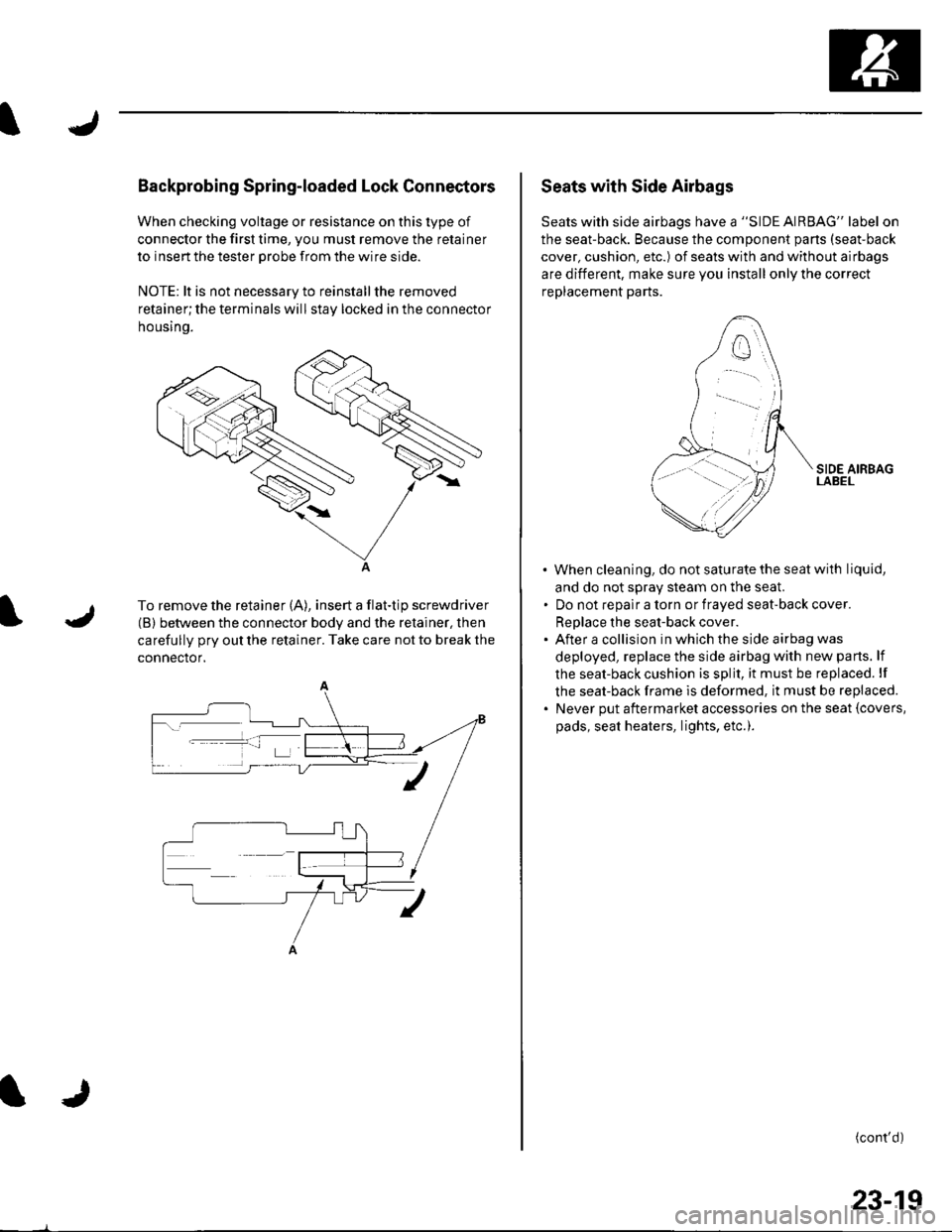
Backprobing Spring-loaded Lock Connectors
When checking voltage or resistance on this type of
connector the first time, you must remove the retainer
to insert the tester orobe from the wire side.
NOTE: lt is not necessary to reinstall the removed
retainer;the terminals will stay locked in the connector
housrno.
A
To remove the retainer (A), insert a flat-tip screwdriver
(B) between the connector body and the retainer, then
carefully pry out the retainer. Take care not to break the
connector.
Seats with Side Airbags
Seats with side airbags have a "SIDE AIRBAG" label on
the seat-back. Because the component pans (seat-back
cover, cushion, etc.) of seats with and without airbags
are different, make sure you install only the correct
replacement parts.
When cleaning, do notsaturatethe seatwith liquid,
and do not sDrav steam on the seal
Do not reoalr a torn or fraved seat-back cover.
ReDlace the seat-back cover.
After a collision in which the side airbag was
deployed, replace the side airbag with new parts. lf
the seat-back cushion is split, it must be replaced. lf
the seat-back frame is deformed, it must be replaced.
Never put aftermarket accessories on the seat {covers,
pads, seat heaters, lights, etc.).
(cont'd)
23-19
Page 1047 of 1139

SRS
16.
DTC Troubleshooting (cont'd)
Turn the ignition switch ON {ll).
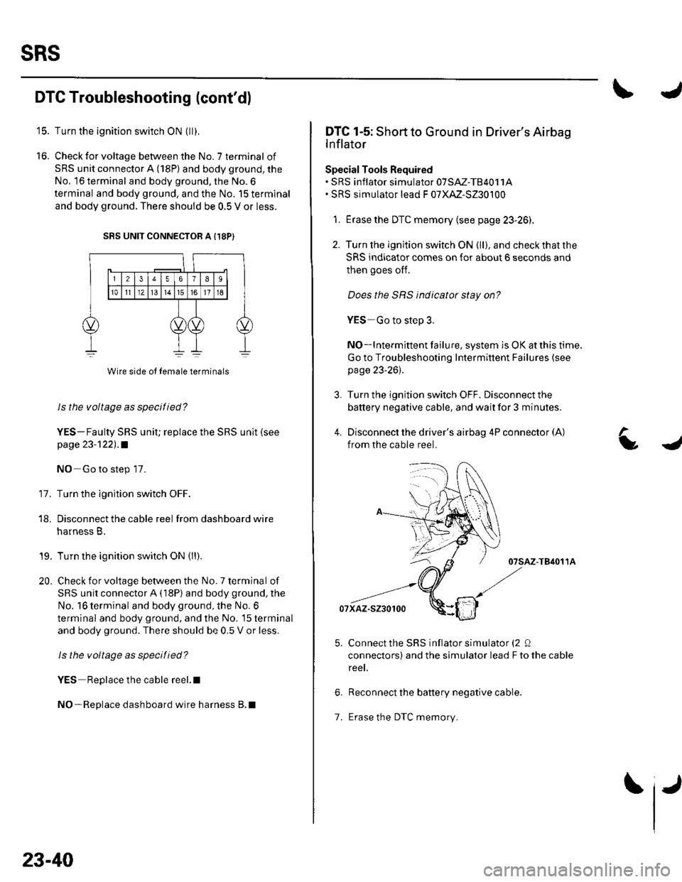
Check for voltage between the No. 7 terminal of
SRS unit connector A (18P) and body ground, the
No. 16 terminal and body ground, the No.6
terminal and body ground, and the No. 15 terminal
and body ground. There should be 0.5 V or less.
SRS UNIT CONNECTOR A {18P)
11.
Wire side ol lemale terminals
Is the voltage as specilied?
YES-Faulty SRS uniU replace the SRS unit (see
page 23-122) .a
NO Go to step 17.
Turn the ignition switch OFF.
Disconnect the cable reel from dashboard wire
harness B.
Turn the ignition switch ON (ll).
Check for voltage between the No. 7 terminal of
SRS unit connector A (18P) and body ground, the
No. 16 terminal and body ground, the No. 6
terminal and body ground, and the No. 15 terminal
and body ground. There should be 0.5 V or less.
ls the voltage as specitied?
YES Replace the cable reel.l
NO-Replace dashboard wire harness B.l
18.
19.
20.
23-40
1.
IJ
L
DTC 1-5: Short to Ground in Driver's Airbag
lnflator
Special Tools Required. SRS inflator simulator 07SM-TB4011A. SRS simulator lead F 07XM-S230100
1. Erase the DTC memory (see page 23-26).
2. Turn the ignition switch ON (ll), and checkthatthe
SRS indicator comes on for about 6 seconds and
then goes oIf.
Does the SBS indicator stay on?
YES Go to step 3.
NO-lntermittent failure, system is OK at this time.
Go to Troubleshooting Intermittent Failures (see
page 23-26).
3. Turn the ignition switch OFF. Disconnect the
battery negative cable, and wait for 3 minutes.
4. Disconnect the driver's airbag 4P connector (A)
from the cable reel.
07sAz-T84011A
07xaz-s230100
Connect the SRS inflator simulator (2 0
connectors) and the simulator lead F to the cable
reet.
Reconnect the battery negative cable.
Erase the DTC memory.
a