Page 1040 of 1139
Self-diagnosis System
A self-diagnosis circuit is built into the SRS uniU when the ignition switch is turned ON (ll), the SRS indicator comes onand goes off after about 6 seconds if the SRS is operating normally.
lf the indicator does not come on, or does not go off after 6 seconds. or if il comes on while driving, it indicates anabnormality in the SRS. The SRS must be inspected and repaired as soon as possible.
For better serviceability, the SRS unit memory stores a DTC that relates to the cause of the malfunction, and the unit isconnected to the data link circuit. This information can be read with the Honda PGM Tester when it is connected to thedata link connector (DLc) (see page 23-23).
23-33
Page 1041 of 1139
SRS
Circuit Diagram
rrssf c ssrarsftrrrl$0[n
J
4
i___':--_:"1
r-----Tr-i
23-34
\J
Page 1045 of 1139
sRs
DTC Troubleshooting {cont'd)
8. Read the DTC.
Is DTC 1-3 indicated?
YES Go to step 9.
NO Short in the driver's airbag; replace the
driver's airbag (see page 23-'l 13).1
9. Turn the ignition switch OFF. Disconnect the
battery negative cable, and wait for 3 minutes.
10. Disconnect the front passenger's airbag 4P
connector from dashboard wire harness B (see step
3 on page 23-21).
1 '1. Disconnect both seat belt tensioner 2P connectors
from the floor wire harness (see step 5 on page 23-
22t.
12. Disconnect SRS unit connectorA (18P)from the
SRS unit (see step 7 on page 23-221.
13. Disconnectthe special tool from the cable reel.
23-38
IJ
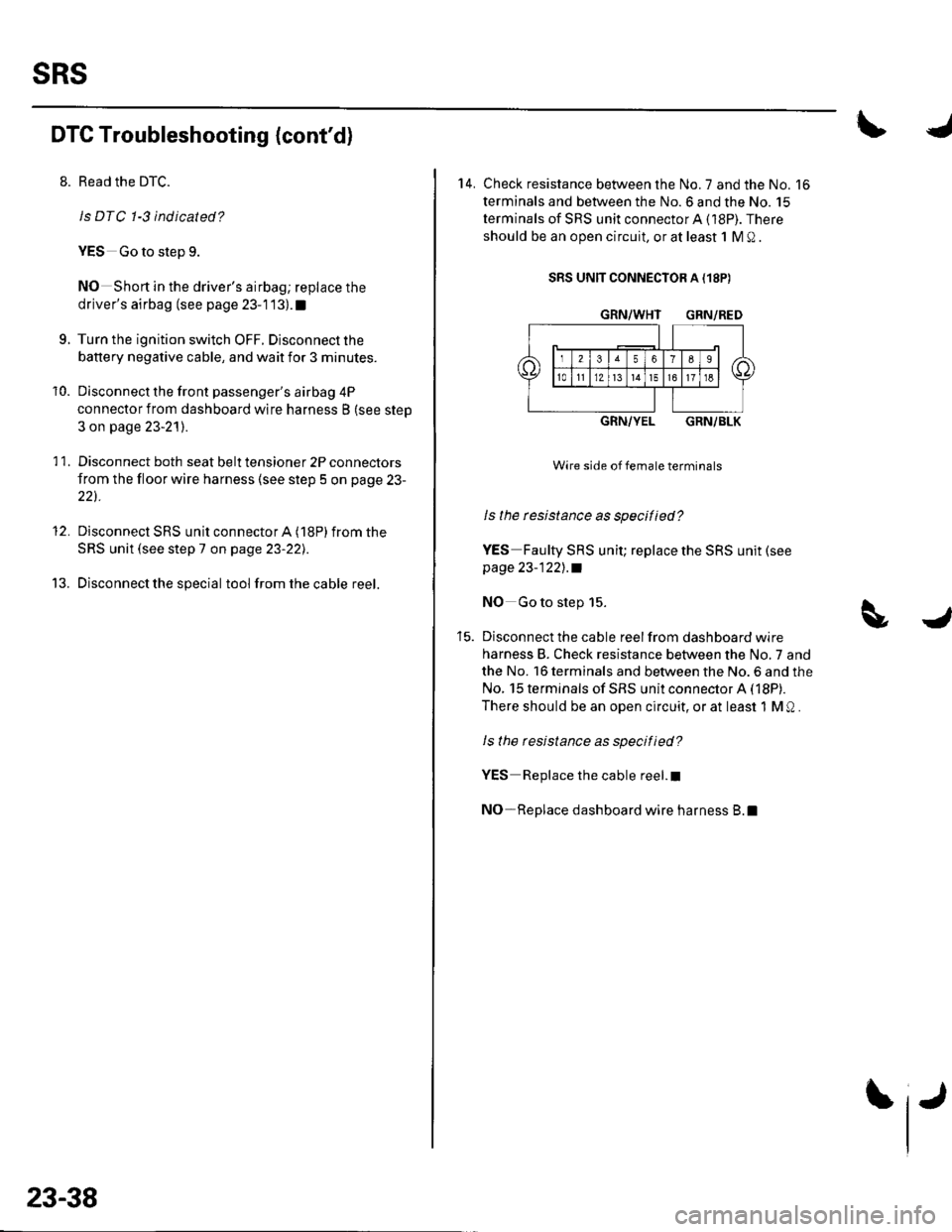
14. Check resistance between the No. 7 and the No. 16
terminals and between the No.6 and the No. 15
terminals of SRS unit connectorA (18P). There
should be an open circuit, or at least 1 M Q .
SRS UNIT CONNECTOR A {18P)
GRN/WHT GRN/RED
GRN/YELGRN/BLK
Wire side of female terminals
ls the rcsistance as specified?
YES Faulty SRS unit; replace the SRS unit (see
page 23-122],.a
NO Go to step 15.
Disconnect the cable reel from dashboard wire
harness B. Check resistance between the No,7 and
the No. 16 terminals and between the No. 6 and the
No. 15 terminals of SRS unit connector A (18P).
There should be an open circuit, or at least 1 M Q .
ls the resistance as specified?
YES Replace the cable reel.I
NO-Replace dashboard wire harness B.l
Page 1048 of 1139
8. Read the DTC.
ls DTC 1-5 indicated?
YES-Go to step 9.
NO Short to ground in the driver's airbag inflator;
replace the driver's airbag (see page 23-1 13).I
9. Turn the ignition switch OFF. Disconnect the
battery negative cable, and wait for 3 minutes.
'10. Disconnectthe front passenger's airbag 4P
connector from dashboard wire harness B (see step
2 on page 23-21) .
11. Disconnect both seat belt tensioner 2P connectors
from the floor wire harness (see step 5 on page 23-
22t.
12. Disconnect SRS unit connector A (18P) fromthe
SRS unit (see step 7 on page 23-22],.
13. Disconnectthe specialtoolfrom the cable reel.
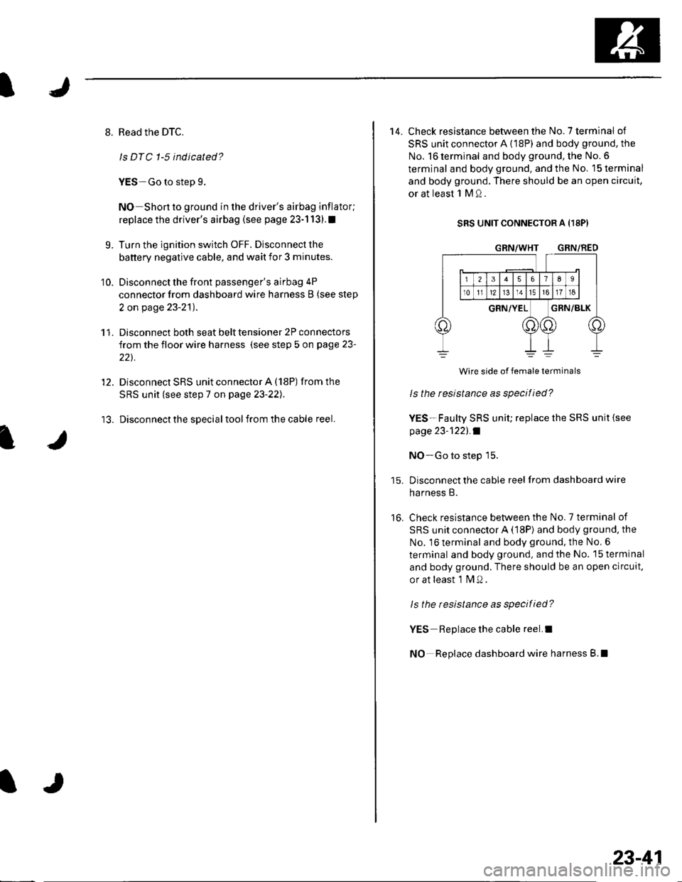
14. Check resistance between the No.7 terminal of
SRS unit connector A {18P) and body ground, the
No. 16 terminal and body ground, the No. 6
terminal and body ground. and the No. 15 terminal
and body ground. There should be an open circuit,
or at least 1 M Q.
SRS UNIT CONNECTOR A I18PI
GRN/WHT GRN/RED
16.
Wire side of female terminals
ls the resistance as specified?
YES-Faulty SRS unit; replace the SRS unit {see
page 23-1221 .f
NO-Go to step 15.
Disconnect the cable reel from dashboard wire
harness B.
Check resistance between the No.7 terminal of
SRS unit connector A (18P) and body ground, the
No. 16 terminal and body ground. the No, 6
terminal and body ground, and the No. 15 terminal
and body ground. There should be an open circuit,
or at least 1 fvl Q .
ls the resistance as specified?
YES Replace the cable reel.I
NO Replace dashboard wire harness B.l
23-41
Page 1051 of 1139
sRs
DTG Troubleshooting (cont'd)
11.
Read the DTC.
ls DTC 2-3 ind icated?
YES Go to step 9.
NO-Short in the front passenger's airbag inflator;
replace the front passenger's airbag (see page 23-
114). t
Turn the ignition switch OFF. Disconnect the
battery negative cable, and wait for 3 minutes.
Disconnect the driver's airbag 4P connector from
the cable reel {see step 2 on page 23-21).
Disconnect both seat belt tensioner 2P connectors
from the floor wire harness (see step 5 on page 23-
221.
9.
10.
23-44
TJ
qJ
'12. Disconnect SRS unit connector A (18P) from the
S R S u n it (see ste p 7 on page 23-22l. .
13. Disconnectthe special tool from dashboard wire
harness B.
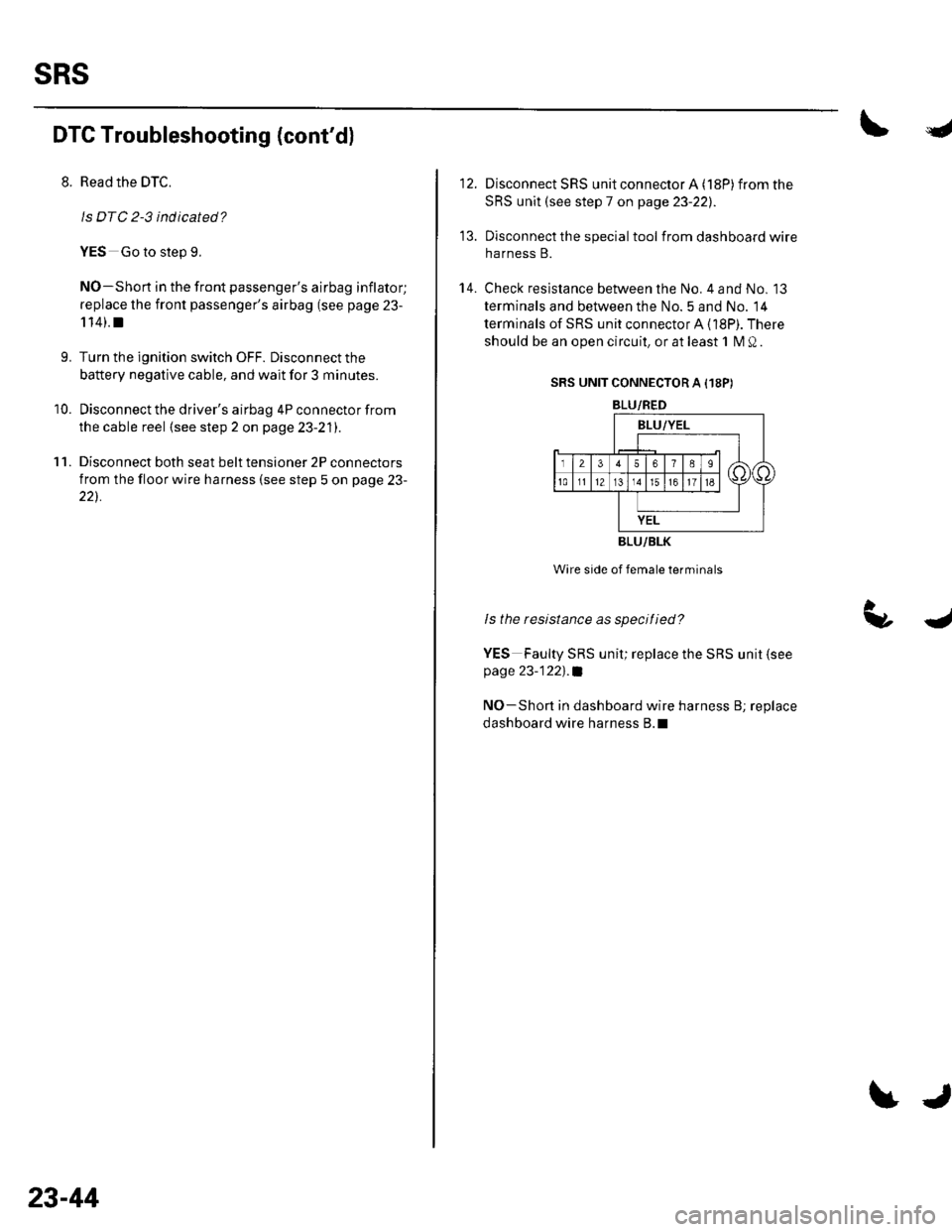
14. Check resistance between the No. 4 and No. 13
terminals and between the No. 5 and No. 14
terminals of SRS unit connector A (18P). There
should be an open circuit, or at least 1 M Q.
SRS UNIT CONNECTOR A I18P)
BLU/RED
BLU/BLK
Wire side of female terminals
ls the resistance as specitied?
YES Faulty SRS unit; replace the SRS unit (see
page 23-122)'.a
NO-Shon in dashboard wire harness B; replace
dashboard wire harness B.l
Page 1054 of 1139
I
7.
11.
9.
10.
Reconnect the battery negative cable.
Erase the DTC memory.
Read the DTC.
ls DTC 2-5 indicated?
YES-Go to step 9.
NO-Shon to ground in the front passenger's
airbag inflator; replace the front passenger's airbag
(see page 23-1 14).1
Turn the ignition switch OFF. Disconnectthe
battery negative cable, and wait for 3 minutes.
Disconnect the driver's airbag 4P connector from
the cable reel {see step 2 on page 23-21).
Disconnect both seat belt tensioner 2P connectors
from the floor wire harness (see step 5 on page 23-
22).
I
I
I
12.
13.
't 4.
Disconnect SRS unit connector A (18P) from the
SRS unit (see step 7 on page 23-221.
Disconnectthe special tool from dashboard wire
harness B.
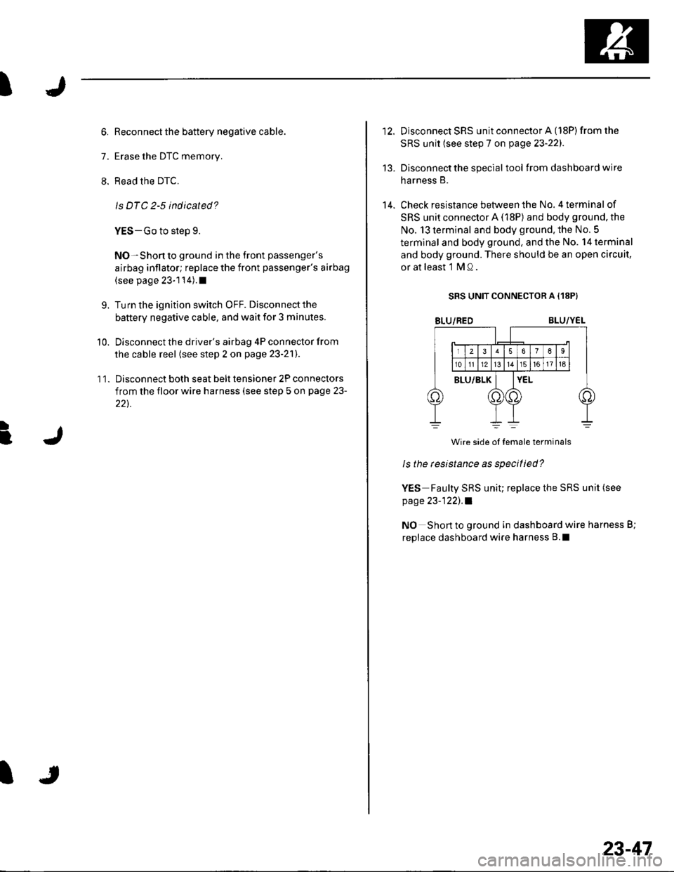
Check resistance between the No. 4 terminal of
SRS unit connector A (18P) and body ground, the
No. 13 terminal and body ground. the No. 5
terminal and body ground, and the No. 14 terminal
and body ground. There should be an open circuit,
or at least l MQ.
SRS UNIT CONNECTOR A {18P}
BLU/REDBLU/YEL
Wire side ol temale terminals
ls the tesistance as specitied?
YES Faulty SRS uniu replace the SRS unit (see
page 23-122), .l
NO Short to ground in dashboard wire harness B;
replace dashboard wire harness B.l
23-47
Page 1057 of 1139
sRs
DTC Troubleshooting (cont'd)
6. Reconnectthe battery negative cable.
7. Erase the DTC memory.
8. Read the DTC.
ls DTC 3-3 indicated?
YES-Go to step L
NO-Shon in the driver's seat belt tensioner;
replace the driver's seat belt (see page 23-4).1
L Turn the ignition switch OFF. Disconnectthe
battery negative cable, and wait for 3 minutes.
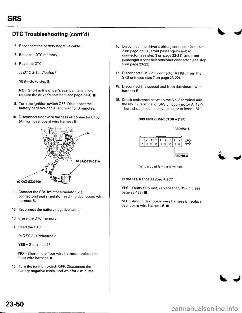
10. Disconnect floor wire harness 4P connector C403(A)from dashboard wire harness B.
07sAz-TB4or 1A
Connectthe SRS inflator simulator (2 Q
connectors) and simulator lead F to dashboard wire
harness B.
Reconnect the battery negative cable.
Erase the DTC memory.
Read the DTC.
ls DTC 3-3 indicated?
YES-Go to step 15.
NO Short in the floor wire harness; replace the
floor wire harness.l
Turn the ignition switch OFF. Disconnect the
battery negative cable, and wait for 3 minutes.
11.
13.
14.
23-50
tJ
16. Disconnect the driver's airbag connector (see step
2 on page 23-211,lront passenger's airbag
connector (see step 3 on page 23-21), and frontpassenger's seat belt tensioner connector (see step
5 on page 23-22).
17. Disconnect SRS unit connector A (18P) from the
SRS unit (see step 7 on page 23-22:,.
18. Disconnect the special tool from dashboard wire
harness B.
19. Check resistance between the No.8 terminal and
the No. 17 terminal of SRS unit connector A ('l8P).
There should be an open circuit, or at least 1 l\4 Q .
SRS UNIT CONNECTOR A I18P)
Wire side of female terminals
ls the resistance as specif ied?
YES Faulty SRS unit; replace the SRS unit (see
page 23-1221.a
NO- Short in dashboard wire harness B; replace
dashboard wire harness B.l
LJ
RED/WHT
RED/BLU
Page 1060 of 1139
t
)
6. Reconnect the battery negative cable.
7. Erase the DTC memory.
8. Read the DTC.
ls DTC 3-5 indicated?
YES-Go to step 9,
NO Shortto ground in the driver's seat belt
tensioner; replace the driver's seat belt(see page 23-4).I
9. Turn the ignition switch OFF. Disconnect the
battery negative cable, and wait for 3 minutes.
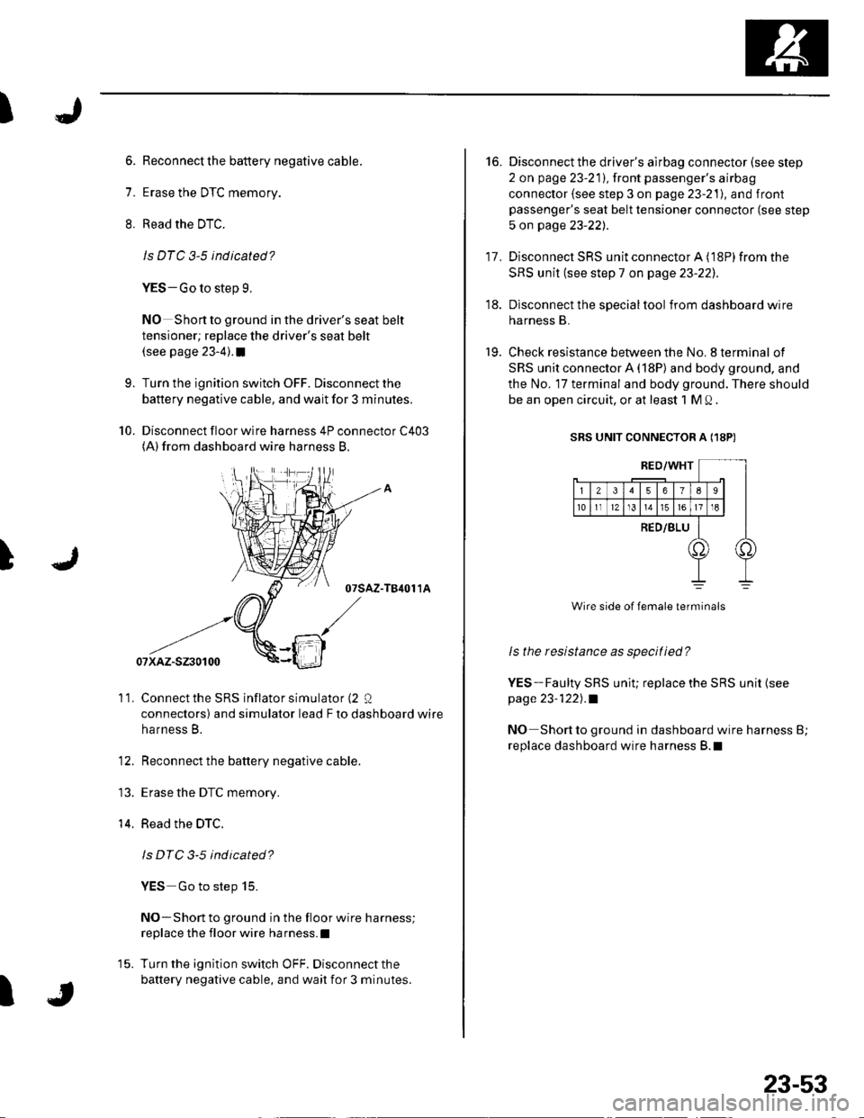
10. Disconnect floor wire harness 4P connector C403(A)from dashboard wire harness B.
07sAz-T84011A
Connect the SRS inflator simulator (2 Q
connectors) and simulator lead F to dashboard wire
harness B.
Reconnect the battery negative cable.
Erase the DTC memory.
Read the DTC.
ls DTC 3-5 ind icated?
YES Go to step 15.
NO-Short to ground in the floor wire harness;
replace the floor wire harness.l
Turn the ignition switch OFF. Disconnect the
battery negative cable, and wait for 3 minutes.
'11.
14.
I
23-53
16. Disconnectthe driver's airbag connector (see step
2 on page 23-211,lront passenger's airbag
connector (see step 3 on page 23-21), and front
passenger's seat belt tensioner connector (see step
5 on page 23-22).
17, Disconnect SRS unit connector A ('l8P) from the
SRS unit (see step 7 on page 23-221.
18. Disconnect the specialtoolfrom dashboard wire
harness B.
19. Check resistance between the No. 8 terminal of
SRS unit connector A (18P) and body ground, and
the No. 17 terminal and body ground. There should
be an open circuit, or at least 1 M Q .
SRS UNIT CONNECTOR A (18P)
ls the resistance as specified?
YES-Faulty SRS uniu replace the SRS unit {seepage 23-122l,.a
NO Short to ground in dashboard wire harness B;
replace dashboard wire harness B.l