Page 920 of 1139
Entry Light Control System
Component Location Index
IGNITION KEY LIGHTTest, page 22-91
IGNITION KEY SWITCHlest, page 22-91
DRIVER'S DOOR SWITCH
CEILING LIGHT/SPOTLIGHTSTest, page 22-96Replacement, page 22-96
REAR CEILING LIGHTTest, page 22-96Replacement, page 22-96
FRONT PASSENGER'SDOOR SWITCH
HATCH LATCH SWITCHTest, page 22-97
CARGO AREA LIGHTTest, page 22-97Replacement, page 22 97
22-89
Page 932 of 1139
Audio Unit Connector Replacement
CavityWireConnects to
1YEUG RNRoof antenna
2YEUREDACC (Power)
3Not used
4Not used
5PNKRioht rear sDeaker (+I
6BLU^/vHTLeft rear sDeaker (+)
7GRN/YELFront oassenqer's door sDeaker {+)/Riqht tweeter (+)
8G RN/BLKDriver's door speaker { + )/Left tweeter (+ )
9RED/BLKLiqhts on siqnal
10WHT/REDConstant power
11Not used
12Not used
Not used
14Not used
taB LU/YE LRioht rear soeaker (-
toBLU/BLKLeft rear sDeaker (
11GRY/REDFront passenqer's door speaker ( )/Riqhttweeter {
18LT GRNDriver's door sDeaker ( )/Left tweetr ( -
19REDDash liqhts briqhtness controller
20BLKG round (G503)
AUDIO UNIT 2OP CONNECTOR
22-101
Page 953 of 1139
Horns
1.
3.
Horn Test/Replacement
Remove the front bumper {see page 20-85).
Disconnect the 1P connector (B), and remove thehorn (A).
Test the horn by connecting battery power to the
terminal (A) and ground to the bracket (B). The horn
should sound.
4. lf it fails to sound, replace it.
22-122
1.
Horn Switch Test
Remove the steering column covers (see page '17-
9).
Disconnecl the dashboard wire harness B 5P
connector (A) from the cable reel (B).
Using a jumper wire . connect the dashboard wire
harness B 5P connector (A) No. 2 terminal to bodyground .
. lf the horns sound, goto step 4.. lf the horns do notsound, checkthese items:- Horn relay- No.7 (15A)fuse in the under-hood fuse/relay
box- Horns (see page 22-122).- An open in the wire
| ../......:....,
Page 955 of 1139
Power Windows
IJComponent Location Index
DRIVER'S WINDOW MOTORTest, page 22-129
UNDER.DASHFUSE/RELAY BOX
POWER WINDOW RELAYIest, page 22-51
FRONT PASSENGER'SWINDOW MOTORTest, page 22-132
tJ
POWER WINDOW MASIER SWITCHInput Test. Daqe 22.126Test, page 22--128Replacement, page 22-133
FRONT PASSENGER'S WINDOW SWITCHInDut Tesl, paqe 22-130f est, page 22-132Beplacement, page 22-133
al.l ' -f..--.--
L-.::
22-124
\J
Page 1002 of 1139

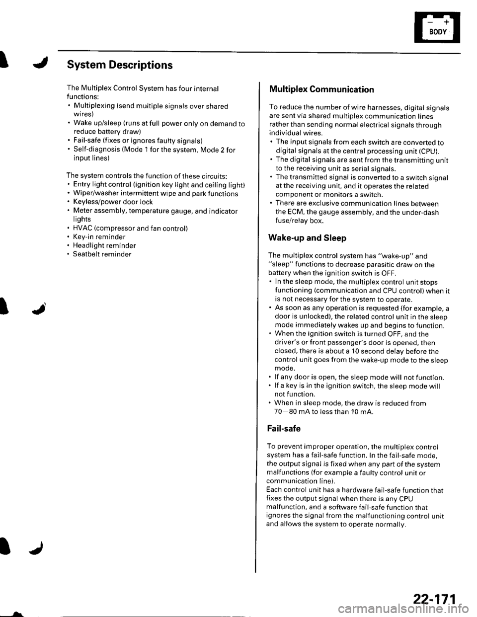
ISystem Descriptions
The Multiplex Control System has four internal
functions:. Multiplexing (send multiple signals over sharedwtres). Wake up/sleep (runs at full power only on demand toreduce battery draw). Fail-safe (fixes or ignores faulty signals). Self-diagnosis (Mode 1 for the system, Mode 2 for
input lines)
The system controls the function of these circuits:. Entry lightcontrol (ignition key lightandceiting light). Wiper/washer intermittent wipe and park functions. Keyless/power door lock. Meter assembly, temperature gauge, and indicator
lights. HVAC (compressor and fan control). Key-in reminder. Headlight reminder. Seatbelt reminder
JI
/ar
22-171
Multiplex Communication
To reduce the number of wire harnesses, digital signals
are sent via shared multiplex communication linesrather than sending normal electrical signals throughindividual wires.. The input signals from each switch are converted todigital signals at the central processing unit (CpU).. The digital signalsaresentfromthetransmitting unitto the receiving unit as serial signals.. The transmitted signal is converted to a switch signalat the receiving unit, and it operates the related
component or monitors a swltch.. There are exclusive communicalion lines between
the ECM, the gauge assembly, and the under,dash
fuse/relay box.
Wake-up and Sleep
The multiplex control system has "wake-up" and"sleep" functions to decrease parasitic draw on the
battery when the ignition switch is OFF.. ln the sleep mode, the multiplex control unit stops
functioning (communication and CPU control) when it
is not necessary for the system to operate.. As soon as any operation is requested (for example, adoor is unlocked), the related control unit in the sleep
mode immediately wakes up and begins to function.. When the ignition switch is turned OFF, and the
driver's or front passenger's door is opened, then
closed, there is about a 10 second delay before the
control unit goes from the wake-up mode to the sleepmode.. lf any door is open, the sleep mode will not function.. lf a key is in the ignition switch, the sleep mode will
not function.. When in sleep mode, the draw is reduced from
70 80 mA to less than 10 mA.
Fail-safe
To prevent improper operation, the multiplex controlsystem has a fail-safe function. In the fail-safe mode,
the output signal js fixed when any part of the systemmalfunctions (for example a faulty control unit orcommunication line).
Each control unit has a hardware fail-safe function thatfixes the output signal when there is any CPUmalfunction, and a software fail-safe function thatignores the signal from the malfunctioning control unitand allows the system to operate normally.
Page 1009 of 1139

I
I
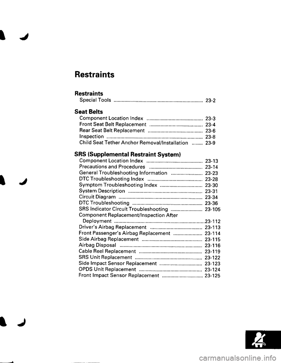
Restraints
Restraints
Special Tools ............. 23-2
Seat Belts
Component Location Index ......................................... 23-3
Front Seat Belt Replacement ....................................... 23-4
Rear Seat Belt Replacement ........................................ 23-6
Inspection .................. 23-8
Child Seat Tether Anchor Removal/lnstallation ........ 23-9
SRS (Supplemental Restraint Systeml
Component Location Index ......................................... 23-13
Precautions and Procedures ,,.,......... 23-14
General Troubleshooting Information ....................... 23-23
DTC Troubleshooting Index .............. 23-28
Symptom Troubleshooting Index ............................... 23-30
System Description ................. ........... 23-31
Circuit Diagram ......... 23-34
DTC Troubleshooting ............... .......... 23-36
SRS Indicator Circuit Troubleshooting ....................... 23-105
Component R e place me n(/ln s pect io n After
Deployment ..............23-112
Driver's Airbag Replacement ............ 23-113
Front Passenger's Airbag Replacement ..................... 23-1 14
Side Airbag Replacement .................. 23-115
Airbag Disposal ....................... ........... 23-116
Cable Reel Replacement .................... 23-119
SRS Unit Repfacement ....................... 23-122
Side fmpact Sensor Replacement ..........,.................... 23-123
OPDS Unit Replacement .................... 23-124
Front fmpact Sensor Replacement .............................. 23-125
Page 1011 of 1139
Seat Belts
IComponent Location Index
CHILD SEATTETHERANCHORSRemoval/lnstallation,page 23-11
REAR CENTER BELT andREAR SEAT BELT BUCKLESstep 1 on page 23-8Inspection, page 23 9
SHOULDERANCHOR ADJUSTERstep 8 on page 23-4
FRONT SEAT BELTReplacement, page 23-4Inspection, page 23 9
I
REAR SEAT BELTBeplacement, page 23.7Inspection, page 23-9
FRONT SEATBELT BUCKLESstep 1 on page 23'6
23-3
Page 1012 of 1139

Seat Belts
Front Seat Belt Replacement
SRS comDonents are located in this area. Review the
SRS component locations (see page 23-13) and the
precautions and procedures (see page 23-14) in the SRS
section before performing repairs or service,
NOTE: Check the front seat belts for damage, and
replace them if necessary. Be careful not to damage
them during removal and installation.
Front Seat Belt
Make sure you have the anti-theft code for the radio,
then write down the frequencies for the preset
buttons.
Disconnect the negative cable from the battery, and
wait at least 3 minutes before beginning work.
Slide the front seat forward fully.
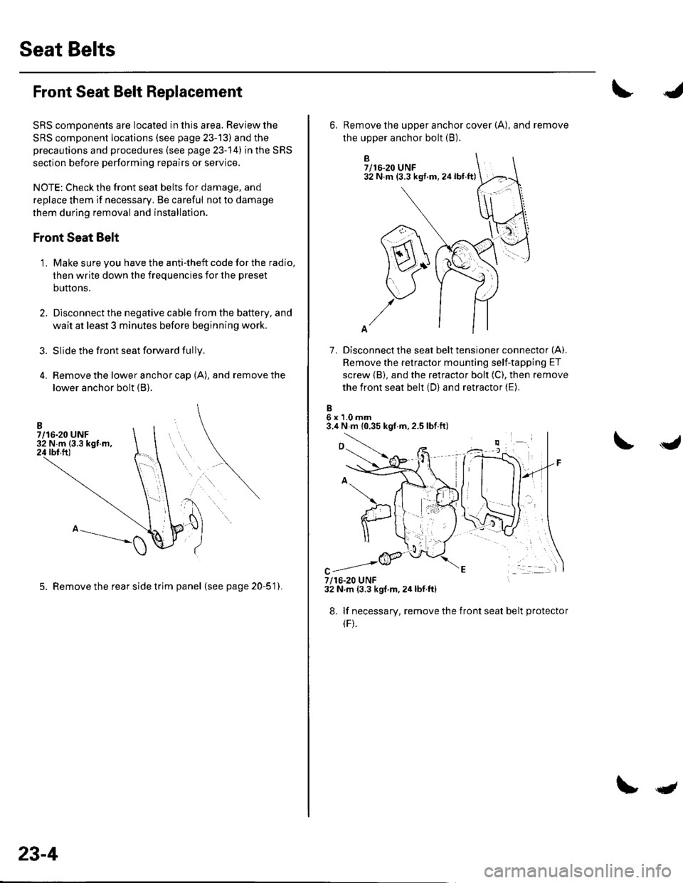
Remove the lower anchor cap (A), and remove the
lower anchor bolt (B).
3.
1.
5. Remove the rear side trim panel (seepage20-51).
23-4
qt
B7/16-20 UNF32 N m (3.3 kgf.m,24lbt.ft)
7. Disconnect the seat belt tensioner connector (A).
Remove the retractor mounting self-tapping ET
screw {B), and the retractor bolt (C), then remove
the front seat belt (D) and retractor (E).
6x1.0mm3.4 N m {0.35 kgf.m,2.5 lbf.ft)
6. Remove the upper anchor cover {A), and remove
the upper anchor bolt (B).
7/16-20 UNF32 N.m (3.3 kgf m,2ir lbf.ft)
8. lf necessary, remove the
(F).
front seat belt protecto