Page 99 of 1139
Cylinder Head
Component Location Index (cont'd)
CAMSHAFT POSITIONICMP} SENSOR
TOP DEAD CENTER(TDC) SENSOR
CAMSHAFTHOLDER
f\
fr
T
F]
Fg
Y
R
LI
CAM CHAINGUIDE B
/EEI
g----- -"-oowetew
EXHAUST CAMSHAFTSPROCKETRemoval, page 6 24Installation, page 6-25
EXHAUST CAMSHAFT
ROCKER ARMASSEMBLYOverhaul, page 6 27Inspection, page 6-28
6-4
Page 100 of 1139
SPRINGRETAINER
EXHAUST VALVESEAL
vALvE / .""or", uo.u,.
ll"
l* I / uo.ur.r","o
--€.i
d:l.\aFl
T1ll
ll
H
,p
2bw
9) \*""'RArNERcovER
wcsrRArNER
CYLINDER HEADRemoval, page 6'23Inspection, page 6-25Installation, page 6-39
EXHAUST VALVERemoval, page 6-31Installation, page 6-37
INTAKE VALVERemoval, page 6 31Installation, page 6 37
CYLINDER HEADGASKET
,H v .-- spntruc>il( G\-r_
\lg
| | g -/ TNTAKE vALVE
II ^-'-- 9E4LI I U- Replacement, Page 6-31
He,tl E- _-/ |NTAKE VALVEY I 1.- GUIDE
U Replacement, page 6-33
i
HEAT SHIELD
6-5
Page 104 of 1139
9. Apply air to the advance hole to release the lock.
Check that the VTC actuator moves smoothly. lf the
VTC actuator does not move smoothly, replace the
VTC acluator.
10.
Valve Glearance Adiustment
NOTE: Adjust the valves only when the cylinder head
temperature is less than 100'F (38'C).
1. Remove the cylinder head cover (see page 6-22).
2. Set the No. 1 piston at top dead center (TDC). The
punch mark (A) on the variable valve timing control
(VTC) actuator and the punch mark (B) on the
exhaust camshaft sprocket should be at the top.
Align the TDC marks (C) on the VTC actuator and
exhaust camshaft sprocket.
{cont'd)
6-9
Page 105 of 1139
Gylinder Head
IValve Clearance Adjustment (cont'd)
3. Select the correct thickness feeler gauge for the
valves you're going to check.
Intake: 0.21 0.25 mm (0.008-0.010 in.)
Exhaust; 0.28 0.32 mm (0.011 0.013 in.)
Adiusting screw locations:
No. 1
EXHAUST
No. 2 No.3 No. 4
No. 1No.4
4.Insert the feeler gauge {A) between the adjusting
screw (B) and the end ofthe valve stem, and slide it
back and forth; you should feel a slight amount of
d rag.
6-10
\.
5. lf you feel toomuchortoolittledrag, loosenthe
locknut (A), and turn the adjusting screw {B) until
the drag on the feeler gauge is correct. .
Tighten the locknut, and recheck the clearance.
Repeat the adjustment if necessary
Rotate the crankshaft 180" clockwise (camshaft
pulley turns 90').
7.
t.\-
8. Check and, if necessary, adjust the valve clearance
on No. 3 cylinder.
Page 110 of 1139
t
18. Remove the cam chain guide A (A) and tensioner
arm (B).
g"'-
19. Remove the cam chain.
,ot./6. | \{n$1J;
Cam Chain Installation
NOTE: Keep the cam chain away from magnetic fields.
1. Set the crankshaft to top dead center (TDC). Align
the TDC mark {A) on the crankshaft sprocket with
the pointer (B) on the cylinder block.
Setthe camshafts to TDC. The punch mark (A) on
the variable valve timing control {VTC) actuator and
the punch mark (B) on the exhaust camshaft
sprocket should be at the top. Align the TDC marks
(C) on the VTC actuator and exhaust camshaft
sprocKet.
(cont'd )
6-15
Page 111 of 1139
Gylinder Head
Cam Chain Installation (cont'dl
3. Installthe cam chain on the crankshaft sprocket
with the colored piece (A) aligned with the punch
mark (B) on the crankshaft sprocket.
Installthe cam chain on the VTC actuator and
exhaust camshaft sprocket with the punch marks(A) aligned with the two colored pieces (B).
B
6-16
{\
5. Installthe cam chain guide A (A) and tensioner arm(B).
6x1.0mm12 N.m{1,2 kgf.m,8.7 tbf.ftt
I'6
8 x 1.25 mm22 N.m12.2kgt.m,16 tbf.ft)
6. Install the auto-tensi
6x1,0mm12Nm(1.2 kgt.m, 8.7 lbf ti)
a
a
Page 118 of 1139

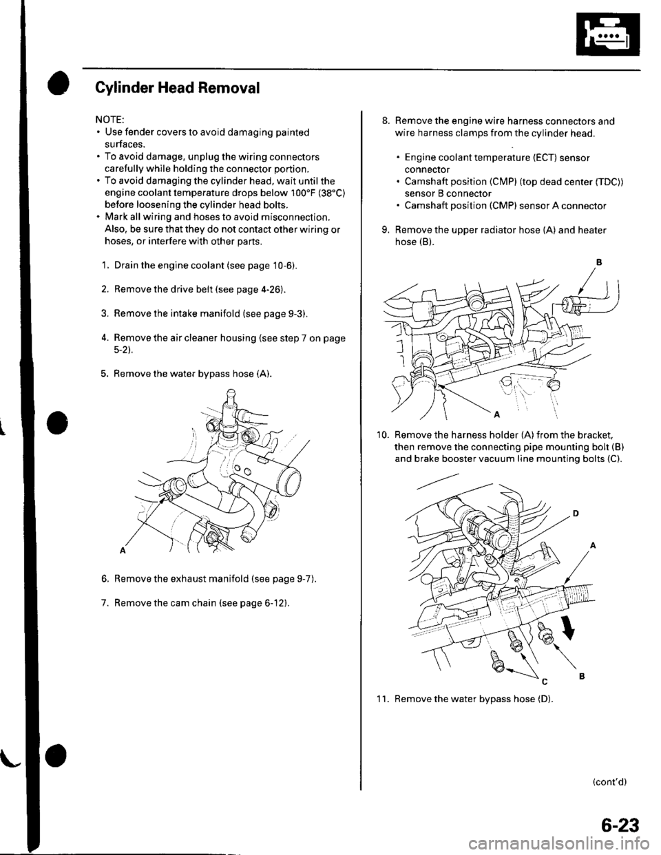
Gylinder Head Removal
NOTE:. Use fender covers to avoid damaging painted
surfaces.
To avoid damage, unplug the wiring connectors
carefully whlle holding the connector portion.
To avoid damaging the cylinder head, wait until the
engine coolant temperature drops below 100'F (38"C)
betore loosening the cylinder head bolts.
Mark all wiring and hoses to avoid misconnection.
Also, be sure that they do not contact other wiring or
hoses, or interfere with other parts.
'1.
2.
3.
Drain the engine coolant (see page 10-6).
Remove the drive belt (see page 4-26).
Remove the intake manifold {see page 9-3).
Remove the air cleaner housing (see step 7 on page
5-2t.
5. Remove the water bypass hose (A).
Remove the exhaust manifold (see page 9-7
Remove the cam chain (see page 6-12).
6.
7.
).
8. Remove the engine wire harness connectors and
wire harness clamps from the cylinder head.
. Engine coolant temperature (ECT) sensor
conneclor. Camshaft position (Cl\4P) (top dead center (TDC))
sensor B connector. Camshaft posilion (CMP) sensor A connector
9. Remove the upper radiator hose (A) and heater
hose (B).
'10. Remove the harness holder (A)from the bracket,
then remove the connecting pipe mounting boh {B)
and brake booster vacuum line mounting bolts {C).
(cont'd)
1 1. Remove the water bvpass hose (D).
6-23
Page 119 of 1139
Cylinder Head
tJ.
Cylinder Head Removal (cont'd)
Remove the rocker arm assembly (see page 6-26).
Remove the cylinder head bolts. To prevent
warpage, unscrew the bolts in sequence 1/3 turn at
a time; repeat the sequence until all bolts are
loosened.
CYLINDER HEAD BOLTS LOOSENING SEQUENGE:
14. Remove the cylinder head.
6-24
VTC Actuator, Exhaust Camshaft\
Sprocket Replacement
Removal:
1. Remove the cam chain (see page 6-12).
2. Hold the camshaft with an open-end wrench, then
loosen the variable valve timing control (VTC)
actuator mounting bolt and exhaust camshaft
sprocket mounting bolt.
Remove the VTC actuator and exhaust camshaft
sprocket.
I\(
I