Page 82 of 1139
Engine Assembly
I
Engine Removal
Special Tools Required
Front subframe adapter EOS02C00001 1
NOTE:. Use fender covers to avoid damaging painted
surfaces.. To avoid damage, unplug the wiring connectors
carefully while holding the connector portion.. Mark all wiring and hoses to avoid misconnection.
Also, be sure that they do not contact other wiring orhoses, or interfere with other parts.
1. Secure the hood in the wide open position (support
rod in the lower hole).
2. Make sure you have the anti-theft code for the radio,
then write down the frequencies for the radio'spreset buttons.
3. Disconnect the negative cable from the battery first,then disconnect the positive cable.
4. Remove the battery.
5. Remove the intake manifold cover.
II
5-2
\,
6. Disconnectthe intake airtemperature (lAT) sensorconnector (A), remove the breather hose (B) and
vacuum hose (C), then remove the air cleaner
housing cover/intake air duct assemblv (D).
AC
7. Remove the air cleaner housing.
Page 95 of 1139

40. Install the air cleaner housinq.
6x1.0mm12 N m (1.2 kgf.m,8.7 lbt.ft)
Install the air cleaner housing cover (A) and
connect the intake air temperature (lAT) sensor
connector (B),
42. Installthe breather hose (C) and vacuum hose 1D).
41.
43. Installthe intake manifold cover.
6x1.0mm12Nm11.2kgf.m.8.7 tbf.ft)
Installthe battery. Clean the battery posts and
cable terminals with sandpaper, then assemble
them and apply grease to prevent corrosion.
Check that the transmission shifts into gear
smoothly.
Inspect for fuel leaks. Turn the ignition switch ON(ll) {do not operate the starter) so that the fuel pump
runs for about 2 seconds and pressurizes the fuel
line. Repeat this operation two or three times, then
check for fuel leakage at any point in the fuel line.
Refillthe engine with engine oil (see page 8-5).
Refill the transmission with fluid (see page 13-3).
Refill the radiator with engine coolant, and bleed
air from the cooling system with the heater valve
open (see page 10-6).
Perform the engine control module (ECM) idle learnprocedure (see page 11-139).
Inspect the idle speed (see page 1 1-138).
Inspect the ignition timing (see page 4-17).
Check the wheel alignment {see page 18-4).
Enter the anti-theft code for the radio, then enter
the customer's radio station presets.
Set the clock.
YE
44.
41.
]tE
46.
48.
49.
52.
53.
54.
50.
51.
55.
5-15
Page 144 of 1139

Engine Block
Crankshaft Main Bearing Replacement
Main Bearing Clearance Inspection
1. To check main bea ring-to-jou rna I oil clearance.
remove the lower block and bearing halves (see
page 1 -12)..
2, Clean each main journal and bearing half witha
clean shop towel.
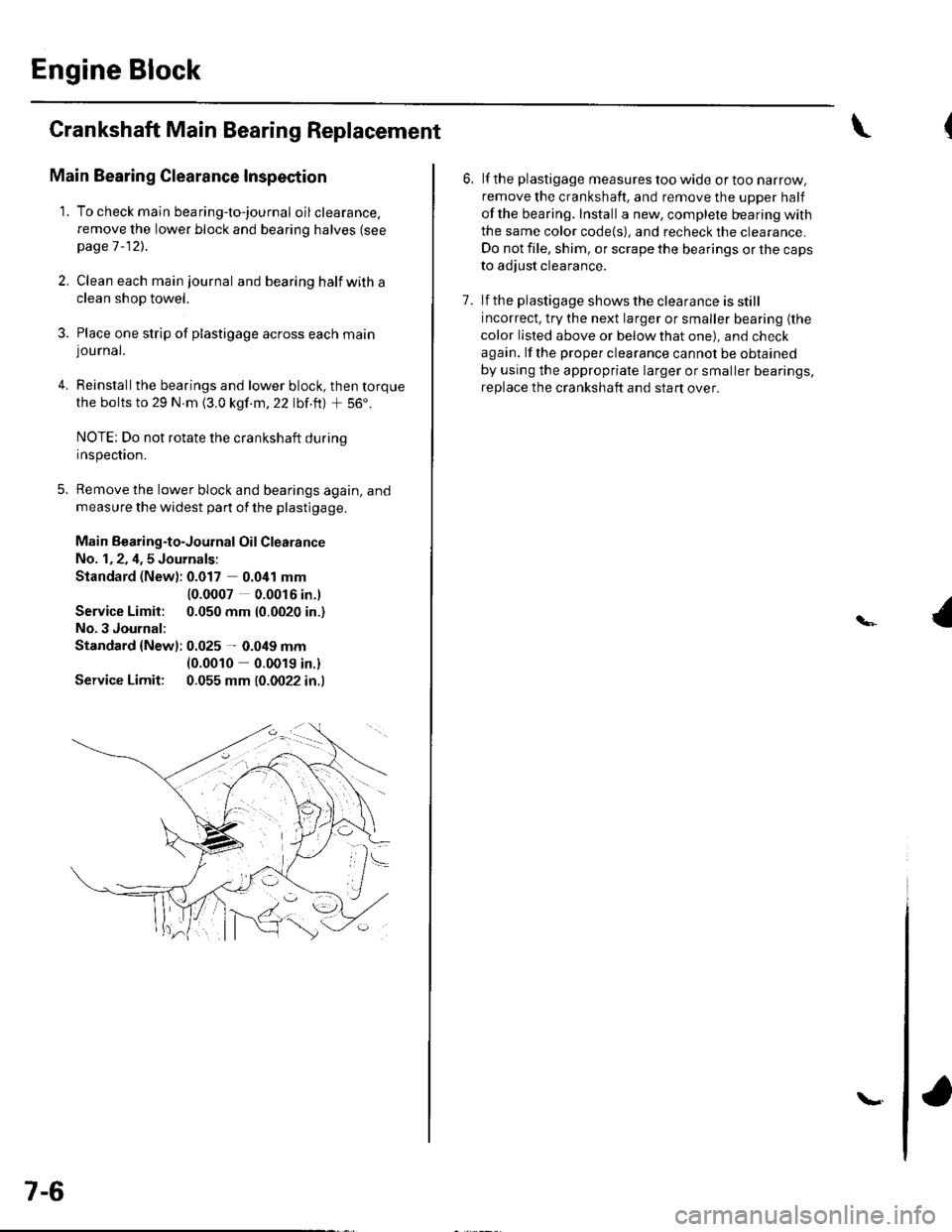
3. Place one strip of plastigage across each main
lou rnal.
4. Reinstallthe bearings and lower block, then torque
the bolts to 29 N.m {3.0 kgf.m,22 lbf.ft) + 56'.
NOTE: Do not rotate the crankshaft during
Inspeclton.
5. Remove the lower block and bearings again, and
measure the widest part of the plastigage.
Main Bearing-to-Journal Oil Clearance
No. 1,2, 4,5 Journals:
Standard (New): 0.017 0.041 mm
Service Limit:
No.3 Journal:
10.0007 0.0016 in.l
0.050 mm {0.0020 in.)
Standard {Newl: 0.025 - 0.049 mm(0.0010 0.0019 in.)
Service Limit: 0.055 mm (0.0022 in.l
7-6
\.
6. lf the plastigage measures too wide or too narrow,
remove the crankshaft. and remove the upper half
ofthe bearing. Install a new, complete bearing with
the same color code{s), and recheck the clearance.
Do not file, shim, or scrape the bearings or the caps
to adjust clearance.
7. lf the plastigage shows the clearance is still
incorrect, try the next larger or smaller bearing (the
color listed above or below that one), and check
again. lf the proper clearance cannot be obtained
by using the appropriate larger or smaller bearings,
replace the crankshaft and start over.
Page 145 of 1139
Main Bearing Selection
Crankshaft Bore Code Location
1. Numbers or letters or bars have been stamped on
the end of the block as a code for the size of each of
the five main journal bores. Write down the crank
bore codes. lf you can't read the codes because of
accumulated dirt and dust, do not scrub them with
a wire brush or scraper. Clean them only with
solvent or detergent.
No. 1 JOURNALIPULLEY END}No. 5 JOURNAL{FLYWHEEL END)
Main Journal Code Location
2. The main journal codes a{e stamped on the
cra n kshaft.
No. 1 JOURNALNo. 5 JOURNAL
(cont'd)
7-7
Page 146 of 1139

Engine Block
Crankshaft Main Bearing
Replacement (cont'd)
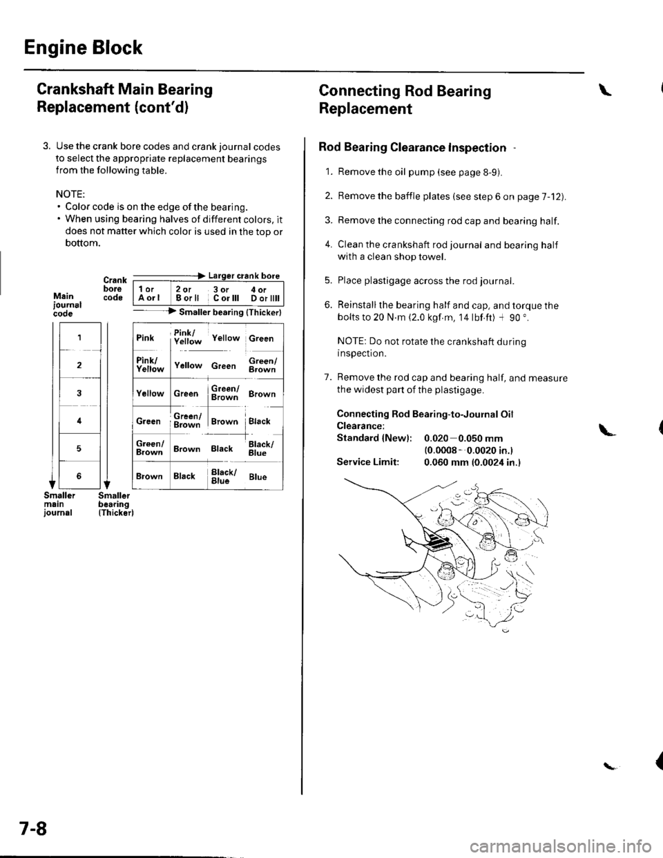
3. Use the crank bore codes and crank journal codes
to select the appropriate replacement bearings
from the following table.
NOTE:. Color code is on the edge of the bearing.. When using bearing halves of different colors. it
does not matter which color is used in the top or
bottom.
Mainiournslcooe
Crank ---=-> Lalger crank bore
bore | 1or 2ot 3or c oi__-lcode IAorl Borll Corlll Dortttt I-- --> Smaller bearing {Thickerl
(Thicker)
1
2
4
5
Pink f!1f;* v"rro* c,""n
ll
f111f;,," v"no* c,""" $;;fl
cr""n $ffi ero-n
ffi#Tr,.*" i.,""*Creen ; g=jiff;i Brown Black
;;lT]*
'---l-'o"*,
Brown Black 6il;
Brack !l;kr ar*
7-8
Connecting Rod Bearing
Replacement
Rod Bearing Clearance lnspection
1. Remove the oil pump (see page 8-9).
2. Bemove the baffle plates (see step 6 on page 7-12).
3. Remove the connecting rod cap and bearing half.
4. Clean the crankshaft rod journal andbearinghalf
with a clean shop towel.
5. Place plastigage across the rod journal.
6. Reinstallthe bearing half and cap, and torque the
bolts to 20 N.m (2.0 kgf.m, 14lbf.ft) -l 90 ".
NOTE: Do not rotate the crankshaft during
inspection.
7. Remove the rod cap and bearing half, and measure
the widest part of the plastigage.
Connecting Rod Bearing-to-Journal Oil
Clearance:
Standard {Newl: 0.020 0.050 mm(0.0008 --0.0020 in.l
Service Limit: 0.060 mm (0.0024 in.)
\
\-
{
Page 147 of 1139

8.
9.
lf the plastigage measures too wide or too narrow,
remove the upper half of the bearing, install a new,
complete bearing with the same color code(s), and
recheck the clearance. Do not file. shim, or scrape
the bearings or the caps to adjust clearance.
lf the plastigage shows the clearance is still
incorrect, try the next larger or smaller bearing (the
color listed above or below that one), and check
clearance agaln. lf the proper clearance cannot be
obtained by using the appropriate larger or smaller
bearing, replace the crankshaft and stan over.
Rod Bearing Selection
1. Inspect each connecting rod for cracks and heat
damage.
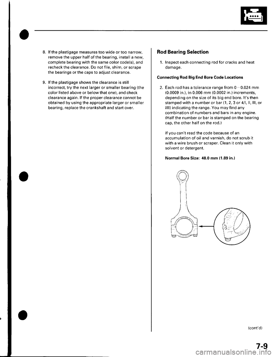
Connecting Rod Big End Eore Code Locations
2. Each rod has a tolerance range from 0 0.024 mm
(0.0009 in.), in 0.006 mm (0.0002 in.) increments,
depending on the size of its big end bore. lt's then
stamped with a number or bar (1, 2,3 or 4/1, ll,lll, ol
llll) indicating the range. You may find any
combination of numbers and bars in any engine.(Half the number or bar is stamped on the bearing
cap, the other half on the rod.)
lf you can't read the code because of an
accumulation of oil and varnish. do not scrub it
with a wire brush or scraper. Clean it only with
solvent or detergent.
Normal Bore Size: 48.0 mm 11.89 in.l
(cont'd)
7-9
Page 148 of 1139
Engine Block
Connecting Rod Bearing Replacement (cont'dl
Connecting Rod Journal Code Location
3. The connecting rod journalcodes are stamped on
the crankshaft.
Connecting Rod Journal Code Location (Letters or
Bars)
No.l JOURNAL No. 4 JOURNAL
7-10
\{
4. Use the big end bore codes and rod journalcodes
to select appropriate replacement bearings from
the following table.
NOTE:. Color code is on the edge of the bearing.. When using bearing halves of different colors, it
does not matter which color is used in the top or
bottom.
Big end ----------> Larger big end boreborecodolorl2oJll3 ol lll4 orllll
---------> Smallsrb.aring {Thickerl
PinkPink/YellowYollow/GrecnGreen
YellowYellow/GreenGreen/BrownBrown
GreenGreen/BrownErown/BlackBlack
BrownBrown/BlackBlack/BlueBlue
Rod
B
c
D
{\
(Thicker)
{
Page 208 of 1139

Fuel and Emissions
Fuel and Emissions Systems
SpecialTools
General Troubleshooting
Information
DTC Troubleshooting lndex ....
Symptom Troubleshooting
1ndex...............
System Descriptions ................
Howto Set Readiness Codes ..
PGM-FlSystem
Component Location Index ....
DTC Troubleshooting ..............
MIL Circuit Troubleshooting ...
DLC Circuit Troubleshooting ..
Injector Replacement ...............
A,/F Sensor Replacement .........
Secondary HO2S
Replacement
ECT Sensor Reolacement .......
CMP Sensor B {TDC Sensor)
Replacement
IAT Sensor Replacement .........
Knock Sensor Replacement ....
CKP Sensor Reolacement .......
VTEC/VTC
Comoonent Location Index ....
DTC Troubleshooting ..............
VTC Oil Control Solenoid
Valve Removal/Test .............
CMP Sensor A Replacement ...
VTEC Solenoid Valve
Removal/lnsoection .............
ldle Control System
Component Location Index
DTC Troubleshooting ..............
A,/C Signal Circuit
TroubleshootinS ...................
Alternator FR Signal Circu it
TroubleshootinS ...................
EPS Signal Circuit
TroubleshootinS ...................
Brake Pedal Position Switch Signal
Circuit Troubleshooting .............
ldle Speed Inspection
ECM ldle learn Procedure .......
Fuel Supply System
Component Location Index
Fuel Pump Circuit Troubleshooting
1't-2
I I-J
11-7
1 1-10
11-12
11-46
11-49
11-52
11-97
11-109
11-111
11-113
11-113
11-114
11-114
11-115
11-115
11-116
11-117
1 1-1 18
11-127
11-128
11-128
11-129
1I-130
I t- t55
11-134
1 1- 135
1 1-137
1 1-138
1 1-139
1 1-140
11-141
11-144
Fuel PressureTest ................... 11-145
Fuel Lines Inspection ............... 11-146
Fuel Line/Ouick-Connect
Fittings Precautions ............. 1 1-148
Fuel Line/Ou ick-Con nect
Fittings Removal .................. 1 1-149
Fuel Line/Ou ick-Con nect
Fittings lnstallation ............... 11-150
Fuel Pressure Regu lator
Replacement ......................... 11-152
Fuel Fifter Replacement ........... 11-152
Fuel Pump/Fuel Gauge Sending
UnitReDlacement ................. 11-153
Fuel Pulsation Damoer
Rep1acement ......................... 11-154
Fuel Tank Reolacement ........... 11-155
Fuel GaugeSending UnitTest ....... 11-156
Low Fuel lndicatorTest ................. 1 1-158
Intake Air System
Comoonent Location Index .... 11-159
Throttle BodyTest ................... 11-160
Intake Air Bypass Control
Thermal Valve Test .............. 11-161
Air Cleaner Reolacement ........ 11-162
Air Cleaner Element
Reolacement ......................... 11-162
Throttle Cable Adjustment ...... 11-163
Th rottle Cable
Removal/lnstallation ............ 1 1-164
Th rottle Body Removal/
Installation .. 11-165
Th rottle Body Disassembly/
Reassemblv .......................... 11-166
Catalytic Converter System
DTC Troubleshooting .............. 1 1-167
PCV System
DTC Troubleshooting .............. 1 1-168
PCV Valve InsDection
and Test ...... 1 1- 169
PCV Valve Reolacement .......... 11-169
EVAP System
Component Location Index .... 11-170
DTCTroubleshooting .............. 11-171
EVAP Two Way Valve Test ...... 11-186
Fuel Tank Vaoor Control
Valve Test ... 11-187
EVAP Canister Replacement ... 11-189
Fuel Tank Vaoor Control
Valve Reolacement .............. 1 1-189Fuel Pressu re Relieving ...........