Page 139 of 1139

Engine Mechanical
Engine Block
Soecial Tools ............. 7 -2
Comoonent Location Index ......................................... 7-3
Connecting Rod and Crankshaft End Play
InsDection .............. 7-5
Crankshaft Main Bearing Replacement ...................... 7-6
Connecting Rod Bearing Replacement ...................... 7-8
Oil Pan Removal ....................... .......... 7-11
Crankshaft and Piston Removal ........ 7-12
Crankshaft Inspection ........................ 7-14
Block and Piston Insoection ........................................ 7-15
Cyfinder Honing ............ .".................... 7 -'17
Piston, Pin and Connecting Rod Replacement .......... 7-18
Piston Ring Replacement ................... 7 -21
Piston lnstallation .................... ........... 7-23
Connecting Rod Bolt Inspection .......' 7 -24
Crankshaft lnstallation .....................'. 7-24
Oil Pan lnstallation .................. ........... 7 -27
Transmission End Crankshaft Seal
lnstallation-ln Car ................... ........' 7 -28
Page 144 of 1139

Engine Block
Crankshaft Main Bearing Replacement
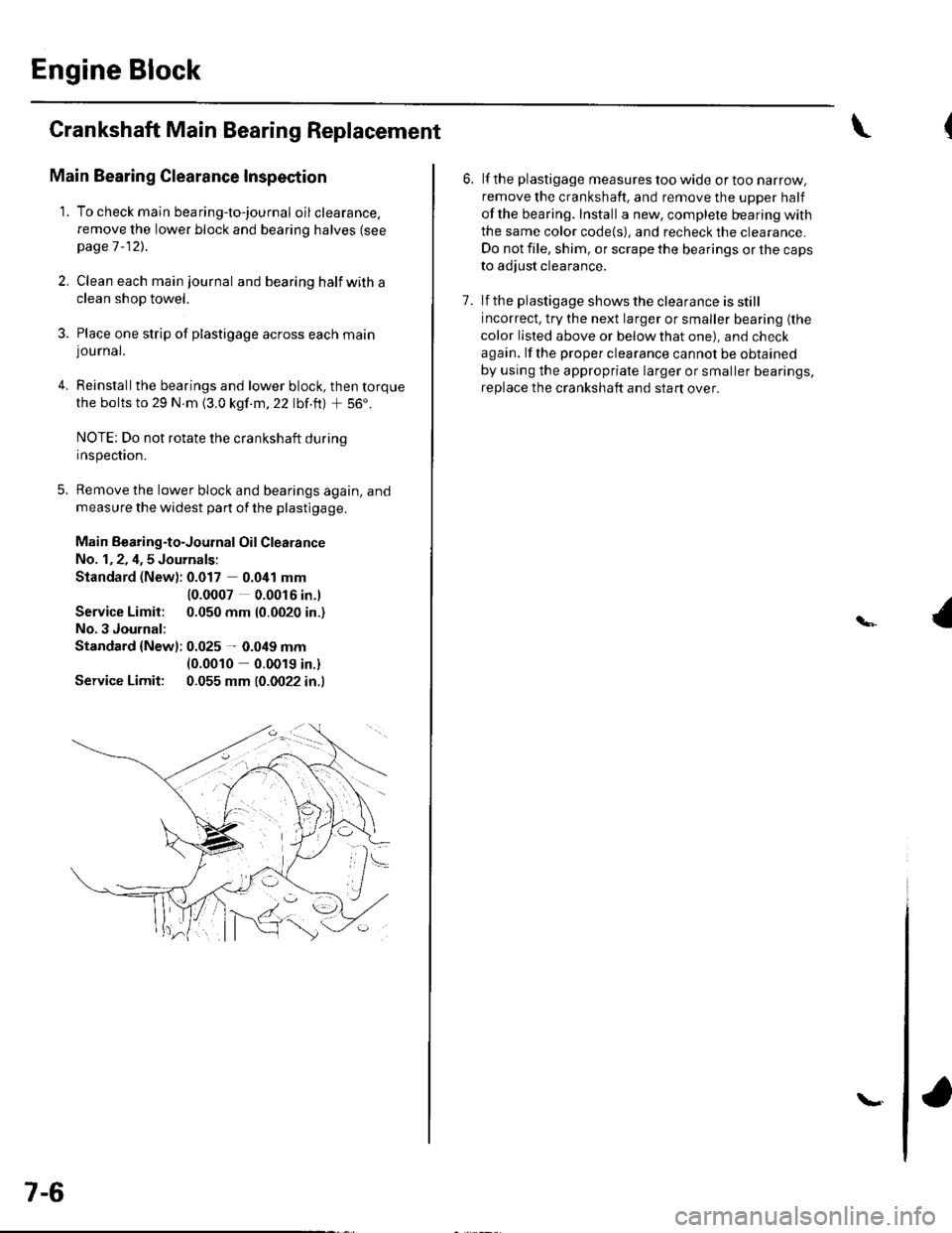
Main Bearing Clearance Inspection
1. To check main bea ring-to-jou rna I oil clearance.
remove the lower block and bearing halves (see
page 1 -12)..
2, Clean each main journal and bearing half witha
clean shop towel.
3. Place one strip of plastigage across each main
lou rnal.
4. Reinstallthe bearings and lower block, then torque
the bolts to 29 N.m {3.0 kgf.m,22 lbf.ft) + 56'.
NOTE: Do not rotate the crankshaft during
Inspeclton.
5. Remove the lower block and bearings again, and
measure the widest part of the plastigage.
Main Bearing-to-Journal Oil Clearance
No. 1,2, 4,5 Journals:
Standard (New): 0.017 0.041 mm
Service Limit:
No.3 Journal:
10.0007 0.0016 in.l
0.050 mm {0.0020 in.)
Standard {Newl: 0.025 - 0.049 mm(0.0010 0.0019 in.)
Service Limit: 0.055 mm (0.0022 in.l
7-6
\.
6. lf the plastigage measures too wide or too narrow,
remove the crankshaft. and remove the upper half
ofthe bearing. Install a new, complete bearing with
the same color code{s), and recheck the clearance.
Do not file, shim, or scrape the bearings or the caps
to adjust clearance.
7. lf the plastigage shows the clearance is still
incorrect, try the next larger or smaller bearing (the
color listed above or below that one), and check
again. lf the proper clearance cannot be obtained
by using the appropriate larger or smaller bearings,
replace the crankshaft and start over.
Page 146 of 1139

Engine Block
Crankshaft Main Bearing
Replacement (cont'd)
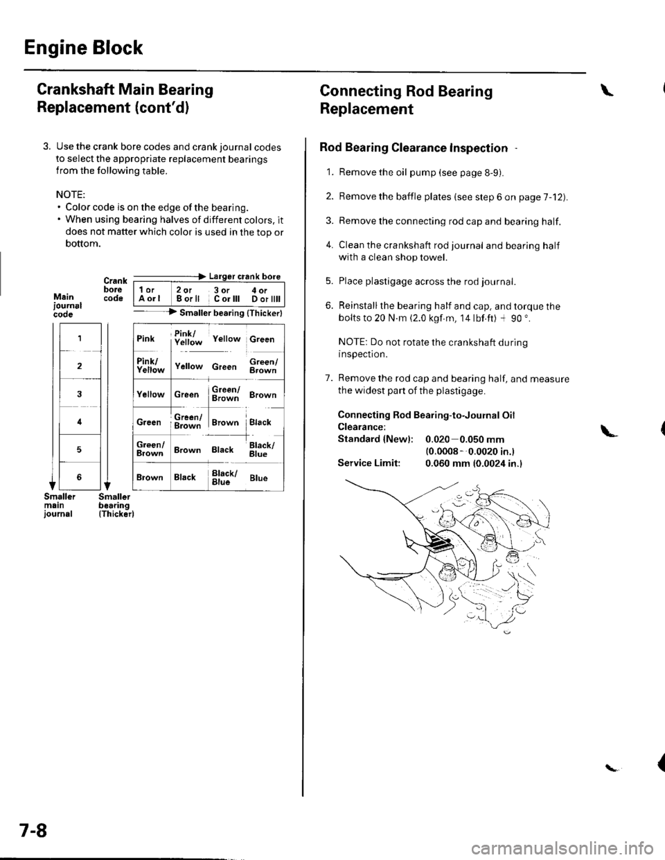
3. Use the crank bore codes and crank journal codes
to select the appropriate replacement bearings
from the following table.
NOTE:. Color code is on the edge of the bearing.. When using bearing halves of different colors. it
does not matter which color is used in the top or
bottom.
Mainiournslcooe
Crank ---=-> Lalger crank bore
bore | 1or 2ot 3or c oi__-lcode IAorl Borll Corlll Dortttt I-- --> Smaller bearing {Thickerl
(Thicker)
1
2
4
5
Pink f!1f;* v"rro* c,""n
ll
f111f;,," v"no* c,""" $;;fl
cr""n $ffi ero-n
ffi#Tr,.*" i.,""*Creen ; g=jiff;i Brown Black
;;lT]*
'---l-'o"*,
Brown Black 6il;
Brack !l;kr ar*
7-8
Connecting Rod Bearing
Replacement
Rod Bearing Clearance lnspection
1. Remove the oil pump (see page 8-9).
2. Bemove the baffle plates (see step 6 on page 7-12).
3. Remove the connecting rod cap and bearing half.
4. Clean the crankshaft rod journal andbearinghalf
with a clean shop towel.
5. Place plastigage across the rod journal.
6. Reinstallthe bearing half and cap, and torque the
bolts to 20 N.m (2.0 kgf.m, 14lbf.ft) -l 90 ".
NOTE: Do not rotate the crankshaft during
inspection.
7. Remove the rod cap and bearing half, and measure
the widest part of the plastigage.
Connecting Rod Bearing-to-Journal Oil
Clearance:
Standard {Newl: 0.020 0.050 mm(0.0008 --0.0020 in.l
Service Limit: 0.060 mm (0.0024 in.)
\
\-
{
Page 149 of 1139
1.
OilPan Removal
Drain the engine oil (see page 8-5).
lf the engine is still in the vehicle, remove the
subframe.
-1 Attach the chain hoist to the engine (see step
35 on page 5-6).-2 Disconnectthe suspension lower arm balljoints (see step 3 on page 18-19).-3 Remove the rear mounl mounting bolts (see
step 39 on page 5-7).-4 Remove the front mount mounting bolt (see
step 40 on page 5-7).-5 Use a marker to make alignment marks on the
reference lines that align with the centers of
the rear subframe mounting bolts. Remove the
front subframe (see step 43 on page 5-8).
Remove the bolts/nuts securing the oil pan.
Drive an oil pan seal cutter between the oil pan and
cylinder block.
5. Cut the oil panseal bystrikingthesideofthecutter
to slide the cutter along the oil pan.
6. Remove the oil pan.
7-11
Page 150 of 1139
Engine Block
Crankshaft and Piston Removal
1. Remove the engine assembly (see page 5-2).
2. Remove the transmission (see page 13-4).
3. Remove the oil pan (see page 7-1 1).
4. Remove the oil pump {see page 8-9).
5. Remove the cylinder head (see page 6-23).
6. Remove the baffle plates.
7. Remove the 8 mm bolts.
E
7-12
8. Remove the bearing cap bolts. To prevent warpage,
unscrew the bolts in sequence 1/3 turn at a time:
repeat the sequence until all bolts are loosened.
Remove the lower block and bearings, Keep all
bearings in order.
\L
(
Page 161 of 1139

Piston Installation
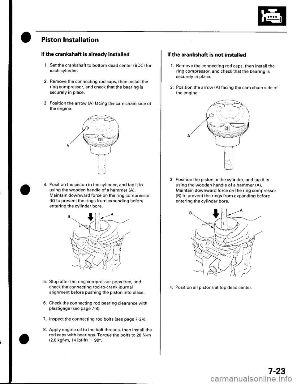
lf the crankshaft is already installed
1. Setthe crankshaftto bottom dead center (BDC) for
each cylinder.
2. Remove the connecting rod caps, then install the
ring compressor, and check that the bearing is
securely in place,
3. Position the arrow {A) facing the cam chain side of
rne engtne.
Position the piston in the cylinder, and tap it in
using the wooden handle of a hammer (A).
N4aintain downward force on the ring compressor(B) to prevent the rings from expanding before
entering the cylinder bore.
Stop after the ring compressor pops free, and
check the connecting rod-to-crank journal
alignment before pushing the piston into place.
Check the connecting rod bearing clearance withplastigage (see page 7-8).
lnspect the connecting rod bolts (see page 7 241.
Apply engine oil to the bolt threads, then install the
rod caps with bearings. Torque the bolts to 20 N.m
{2.0 kgf m, 14 lbf ft) + 90'.
6.
7.
2.
1.
lf the crankshaft is not installed
Remove the connecting rod caps. then install the
ring compressor, and check that the bearing is
securely in place.
Position the arrow (A)facing the cam chain side of
Ine engrne.
Position the piston in the cylinder, and tap it in
using the wooden handle of a hammer (A),
Maintain downward force on the ring compressor(B) to prevent the rings from expanding before
entering the cylinder bore.
4. Position all pistons attop dead center.
\--lno n\-.--l. ^u t
>-*/zi
.,.'_\pf{
wr
(( 'V,/ :
7-23
Page 162 of 1139
Engine Block
Connecting Rod Bolt Inspection
Measure the diameter of each connectinq rod bolt
at Doint A and ooint B.
35 mm
Calculate the difference in diameter between point
A and point B.
Point A-Point B = Difference in Diameter
Diflerence in Diameter:
Specification: 0 0.1 mm (0 0.004 in.)
lf the difference in diameter is out of tolerance,
replace the connecting rod bolt.
1.
3,
mm
7-24
\-
Crankshaft Installation
Special Tools Bequired. Driver 07749-0010000. Attachment, 24 x 26 mm 07746-0010700. Oil seal driver attachment 96 o7ZAD-PNAAl00
1. Install the crankshaft end bushing with the special
tools when replacing the crankshaft. Drive in the
crankshaft end bushing until the special tools
bottom aqainst the crankshaft.
07749-0010000
07746-00'l
Check the connecting rod bearing clearance with
plastigage {see page 7-8).
Check the main bearing clearance with plastigage
(see page 7-6).
lnspectthe connecting rod bolts (see pageT-241.
(
I\-(
4.
a
Page 163 of 1139

5. Installthe bearing halves in the cylinder block and
conneclrng rods.
6. Apply a coat of engine oilto the main bearings and
rod bearings.
7. Hold the crankshaft so rod journal No.2and rodjournal No. 3 are straight up, and lower the
crankshaft into the block.
8. lnstallthe thrust washers (A) in the No. 4 journal of
the cylinder block.
Apply engine oil to the threads ot the connecting
rod bolts,
Seat the rod journals into connecting rod No. 1 and
connecting rod No. 4. Line up the mark (B) on the
connecting rod and cap, then installthe caps and
bolts finger-tight.
Rotate the crankshaft clockwise, and seat thejournals into connecting rod No.2 and connecting
rod No. 3. Line up the mark on the connecting rod
and cap, then install the caps and bolts finger-tight.
9.
10.
'11 .
\-1
12. Tighten the connecting rod bolts to 20 N.m(2.0 kgf.m, 14 lbf.ft).
13. Tighten the connecting rod bolts an additional 90".
14. Remove old liquid gasket from the lower block
mating surfaces, bolts and bolt holes.
15. Clean and dry the lower block mating surfaces.
16. Apply liquid gasket, P/N 08718-0009, evenly to the
cylinder block mating surface of the lower block
and to the innerthreads ofthe bolt holes.
NOTE: Do not install the parts if 5 minutes or more
have elapsed since applying liquid gasket. Instead,
reapply liquid gasket after removing old residue.
(cont'd)
.\
,i,
Apply liquid gasketalong the broken line.
7-25