2003 HONDA CIVIC Oil bolt
[x] Cancel search: Oil boltPage 822 of 1139

Compressor Thermal Protector
Replacement
1. Remove the bolt, the ground terminal (A), and the
holder (B). Disconnect the field coil connector (C).
then remove the thermal protector (D).
Replace the thermal protector (A) with a new one,
and apply silicone sealant (B) to the bottom of the
thermal Drotector.
A
3. lnstall in the reverse order of removal.
7.4 N.m(0.75 kgf.m,5 rbf.ftl
Compressor Relief Valve
Replacement
2.
1.
4.
Recover the refrigerant with a recovery/recycling/
charging station (see page 21-53).
Remove the relief valve (A) and the O-ring (B). Plug
the opening to keep foreign mafter from entering
the system and the compressor oil from running
out.
A9,8 N.m(1.0 kgf m,7.2lbf.ft)
Clean the mating surfaces.
Install a new O-ring on the relief valve, and apply a
thin coat of refrigerant oil to the O-ring.
Remove the plug, and install and tighten the relief
valve.
Charge the system (see page 21-55).
21-51
Page 823 of 1139

Heating and Air Conditioning
Gondenser Replacement
1.
6x1.0mm9.8 N.m ('1.0 kgf.m,7.2lbf.ft)
Recover the refrigerant with a recovery/recycling/
charging station (see page 21-53).
Remove the front bumper {see page 20-85).
Remove the bolts, then disconnect the discharge
line (A) and the condenser line (B) from the
condenser. Plug or cap the lines immediately after
disconnecting them to avoid moisture and dust
conlamtnaflon.
,t\
6x1.0mm9.8 N.m (1.0 kgt.m.7.2lbf.ft)
21-52
4, Remove the mounting bolts, then remove the
condenser by lifting it up. Be careful not to damage
the radiator or the condenser fins when removino
the condenser.
6 x '1.0 mm9.8 N.m ('1.0 kgf.m,7.2 tbl.ftl
5.lnstallthe condenser in the reverse order of
removal, and note these items.
. lf you're installing a newcondenser, add
refrigerant oil (KElHlN SP- 10) lsee page 21'6).. Replace the O-rings with new ones at each fitting,
and apply a thin coat of refrigerant oil before
installing them. Be sure to use the correct O-rings
for HFC-134a (R-'134a)to avoid leakage.. lmmediately after using the oil, reinstallthe cap
on the container, and seal it to avoid moisture
absorption.. Do not spillthe refrigerant oil onthevehicle;it
may damage the paint. lf the refrigerant oil
contacts the paint, wash it off immediately.. Be careful not to damage the radiator or the
condenser fins when installing the condenser.. Charge the system (see page 21-55).
t -"'.
f,
t-
-li .:)-:.-- ---- - -'
Page 828 of 1139

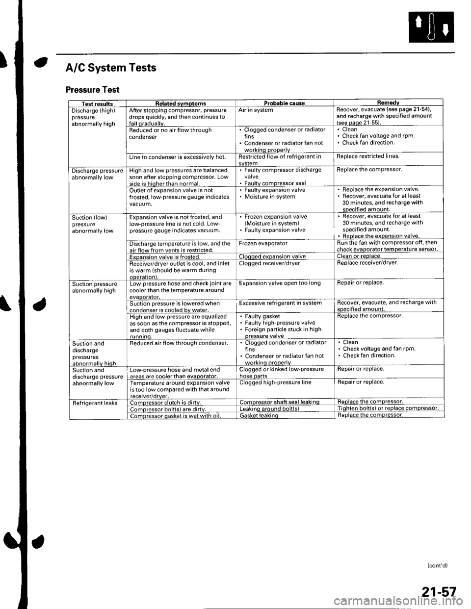
A/C System Tests
Pressure Test
Test resultssvmotom3DGaUSeDischarge (high)pressureabnormally high
After stopping compressor, pressure
drops quickly, and then continues toAir in systemRecover, evacuate (see page 21-54),and recharge with specified amount{see oaoe 21 55).
Beduced or no air flow throughcondenserClogged condenser or radiatorfinsCondenser or radiator fan not
CleanCheck fan voltage and rpm.Check fan direction.
Line to condenser is excessively hot.Restricted flow of refrigerant inReplace restricted lines.
Discharge pressureHigh and low pressures are balancedsoon after stopping compressor, Lowside is hioherthan normal.
. Faulty compressor dischargevalve. Faultv comoressor seal
Beplace the compressor.
Outlet of expansion valve is notfrosted, low pressure gauge indicatesFaulty expansion valveMoisture in system
. Replace the expansion valve.. Recover, evacuate for at least30 minutes, and recharge withsDecified amount.
Suction (low)pressureabnormally low
Expansion valve is not frosted, andlow-pressure line is not cold. Lowpressure gauge indicates vacuum,
' Frozen expansion valve(Moisture in system). Faulty expansion valve
Recover, evacuate for at least30 minutes, and recharge withspecified amount.Beplace the expansion valve.
Discharge temperature is low, and theair flow from vents is restricted.Frozen evaporatorRun the fan with compressor off, thencheck evaooratot temoerature sensor.
Exoansion valve is frosted.ean or reolace,
Receivetdryer outlet is cool, and inletis warm (should be warm duringooeralton),
Clogged receiver/dryerReplace receaver/dryer.
Suction pressureabnormally highLow pressure hose and check joint arecooler than the temperature aroundevaoorator,
Expansion valve open too longBepair or replace.
Suction pressure is lowered when..nrlenser is cooled bv water.Excessive refrigerant in systemRecover, evacuate, and recharge withqnp.ifie.lamo'rnr
High and low pressure are equalizedas soon asthecompressor is stopped,and both gauges fluctuate while
Faulty gasketFaulty high pressure valveForeign panicle stuck in high
Replace the compressor.
Suction anddaschargepressuresabnormallv hioh
Reduced air flow through condenser.. Clogged condenser or radiatorfins' Condenser or radiator fan notworkino orooerlv
CleanCheck voltage and fan rpm.Check fan direction.
Suction anddischarge pressureabnormally low
Low-pressure hose and metalendareas are coolerthan evaoorator,Clogged or kinked low-pressurehose oartsRepair or replace.
Temperature around expansion valveis too low compared with that aroundClogged high-pressure lineRepair or replace,
Fefrigerant leaks:omoressor clulch is dirtv.:omoressor shaft seal leakinqReolace the comDressor,
lomoressor bolt(s) are dirtv.no around bolt(s)Tiohten bolt{s) ot reolace comDressor,
;omDressor oasket is wet with oil.ietnoace the comoressor.
(cont'd)
21-57
Page 937 of 1139

Rear Window Defogger
Function Test
NOTE:. Be careful not to scratch or damage the defogger
wires with the tester probe.
. Before testing, check the No. 11 (30A) fuse in the
under-hood fuse/relay box and No. '14 ('10A) fuse in
the under-dash fuse/relay box.
1. Check for voltage between the ve rtica I dividersand
body ground with the ignition switch and defogger
switch ON.
There should be voltage as shown.
. lf there is no voltage. checkfor:- faulty defogger relay.- an open in the BLK, BLK,/YEL, or YEL/BLK wire.- taulty heater control panel.
. lf there is battery voltage, goto step 2.
6V
Check for continuity between the negative terminal(B) and body ground.
lf there is no continuity, check for:. an open in the BLK wire.. Poor body ground at the window antenna coil
mounting bolt.
Touch the voltmeter positive probe to the halfway
point of each defogger wire. and the negative
probe to the negative terminal,
There should be about 6 V with the ignition switch
and the defogger switch ON.
. lf thevoltage is asspecified, the defoggerwlre is
oK.. lf the voltage is not as specified, repair the
defogger wire.- lf it is more than 6 V, there is a break in the
negative half of the wire.- lf it is less than 6 V, there is a break in the
positive half of the wire.
2.
22-106
2.
Defogger Wire Repair
NOTE: To make an effective repair, the broken section
must be no longer than one inch.
1. Lightly rub the area around the broken section (A)
with fine steel wool, then clean it with alcohol.
Carefully mask above and below the broken portion
of the defogger wire (B) with transparent tape {C).
Mix the silver conductive paint thoroughly. Using a
small brush, apply a heavy coat of paint extending
about 1/8 inch on both sides of the break. Allow 30
minutes to dry.
Check for continuity in the repaired wire.
Apply a second coat of paint in the same way. Let it
dry 3 hours before removing the tape.
5.
Page 1023 of 1139

sRs
Precautions and Procedures {cont'dl
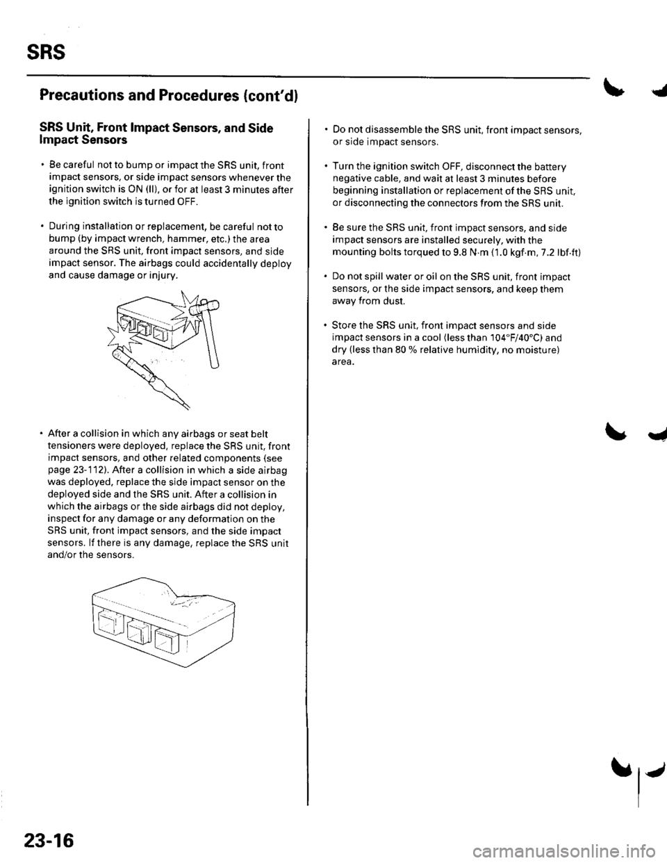
SRS Unit, Front lmpact Sensors, and Side
lmpact Sensors
. Be careful not to bump or impact the SRS unit, front
impact sensors, or side impact sensors whenever the
ignition switch is ON (ll), or for at least 3 minules after
the ignition switch is turned OFF.
. During installation orreplacement, be careful notto
bump (by impact wrench, hammer, etc.) the area
around the SRS unit, front impact sensors, and sjde
impact sensor. The airbags could accidentally deploy
and cause damage or injury.
After a collision in which any airbags or seat belt
tensioners were deployed. replace the SRS unit, front
impact sensors, and other related components (see
page 23-112). After a collision in which a side airbag
was deployed. replace the side impact sensor on the
deployed side and the SRS unit. After a collision in
which the airbags or the side airbags did not deploy,
inspect for any damage or any deformation on the
SRS unit, front impact sensors, and the side impact
sensors. lf there is any damage, replace the SRS unit
and/or the sensors.
23-16
.j
. Do not disassemble the SRS unit, front impact sensors,
or side impact sensors.
. Turn the ignition switch OFF, disconnect the battery
negative cable, and wait at least 3 minules before
beginning installation or replacement of the SBS unit,
or disconnecting the connectors from the SRS unit.
. Be sure the SRS unit, front impact sensors, and side
impact sensors are installed securely. with the
mounting bolts torqued to 9.8 N.m (1.0 kgf.m,7.2 lbf.ft)
. Do not spill wateroroil on the SRS unit, front impact
sensors, or the side impact sensors, and keep them
away from dust.
. Store the SRS unit, front imDact sensors and side
impact sensors in a cool (less than 104"F/40'C) and
dry (less than 80 % relative humidity, no moisture)
area.
I
Page 1134 of 1139

Service Manual Index
(cont'dl
Brake System Indicator CircuitCircuit DiagramConventional Brake Components..... 19-9TroubleshootingABS/TCS Components .... ....... ...... 19-55
Bulb, GeugeRep|acemenl................ .. ............2263
Bulb, HeadlightReplacement ......................................... 22-A1
Bumper, FrontRemoval/1nsra11ation ............................ 20 85
Bumper, RearRemoval/lnstallation... ... . .....20.86
Combination Light SwilchTesVReplacement ..............................22 80
Connecting Rod BearingsRep|acement...................... .......-....7-8
Connecting Rod Boltsf nspection ....................-.-.-.-.................... 7 -24
Connecting RodsInspection ........,,.,.,...,.,.,.,.,,,,.,,,.,.,.,.,.,.,.,.. 7 5
Connectors(See first page of this Index)
Conventional Brake Component3Component Location Index ................... 19'3Troub1eshootin9 ..................................... 19-4
Cylinder Head AssemblyComponent Location Index ..................... 6-3Inspection ................................................. 6 6Removal ..........&�23Insta11alion .............................................. 6 39
Cylinder Head Cover8emova1 ..............-.-................................. 6-22Installation ..............................................6-41
Cylinder Head, BareInspecton..,.....,.
D
c
Cable ReelReplacement....................................... 23-1 19
CamshaftInspection .......................-...-................... 6-29
Cargo Area LightTesVRep1acement ................................ 22-97
CarpetReplacement.....-...-..... ... ......-.20-55
Ceiling Light-estrReplacement ................................ 22.96
Charging SystemComponent Location Index................... 4-20Circuit Diagram ...................................... 4-21
19-8
CoolantInspection .................. ..... .. 106Replacement................. ... . .. 10 6
Coolant Temperature Gat|geTroub1eshootin9................................... 22 64
Cooling SyslemComponent Location Index................... 10-2
Countershaft BearingsReplacement............... ..................... 13-42
Cowl CoverReplacement............... .. ..... ....20-95
CrankshaftRemoval .................................................. 7 -12
Repair ..................
Inspec(on,,,,,........1 14
Dampers. FrontReplacement................ ..................... 18 20
Oampers, RearRep1acement......................................... 18-34
Dash VentsBemoval/lnstallation .-.......................... 20-64
DashboardBemoval/1nsta11ation ............................ 20-66
Oashboard Center PanelRemoval/1nstaf 1ation ............................ 20 62
Dashboard Lower CoverRemoval/lnstallation ...................... 20-59, 63
Dashboard Under CoverRemoval/lnstallation ............................ 20 60
Diff erential Carrier Bearings, M/TRep1acement,,......,...,...,.,.,,,.,.,,,........,.,. 13-54
Ditferential Oil Seals, M/T8ep1acement......................................... 13-55
Differential Pinion Gears, M/TInspection .,....-,.,,,.,..,.-,.,.........,.,.,,, 13 53
OLC CircuitTroubleshooting ................................ 1 1-109
Door GlassRep1acement.,.,,,,,,,,,,,.,,,,,,,,,,.,.,.,.,.,,,,,,.,, 20-9Adjustment. .. .....................20-11
Door Glass WeathelstripsReplacement .............-.. . . . ..........-......20 10
Door LatchesReplacement ..........-.-.............................. 20-7
Door Lock ActuatorsTest ...................................................... 22-154
Door Lock Knob SwitchesTest -......... . . . - . . . . . . . . ......22-160
Door Lock SwitchesTest ........... ............................ ............. 22-160
Door Outer HandlesRep1acemen1 ........................................... 20-6
3
Child Seat Tether AnchorRemoval/lnstaf lat;on .. ........................ 23 11
CKP (Crankshaft Position) SonsorReplacement....................................... 1 1-116
ClutchComponentLocation 1ndex................... 12-3Rep1acemen1........................................... 12-9
Clutch InteYlock SwitchTest.....-........-...-............. ...---.-.......4-6
Clutch Master CylinderReplacement........................................... 12 5
clutch PedalAdjustment ............................................. 12 4
Clutch Pedal Position SwitchTest.,.,,,,,.,,,.,.,,,,,,.,.,,,,,,,,,.,,,,,.. ......445
lnstallation.................. . ..... .....1-24
Crankshalt Main BearingsReplacement........-.-.................................. 7-6
CrankshaftOil Seal,Transmission End1nstanation .............................................. 7 28
Crankshafl PulleyRemoval/lnstallation -..................-.......... 6-1 1
Cruise Control Actuator
Troubleshooting
Clutch Slave CylindorBeplacemeit...
...................... 4-43
.......4-22
Test
12-1
RepIacement........................................... 4-44
Cruise Control Actuator CableAdjustment ............................................. 4 45
Cruise Control Main SwitchTesVRep1acement .................................. 4 42
Cruise Control Set/Resume/Cancel SwitchTesVRep1acement .................................. 4 42
Cruise Control SystomComponent Localion Inde\................... 4-36Circuit Diagram ....-................................. 4 37
Cruise Control UnitInputTest.............................. .. ...4,40CMP {Camshaft Positionl Senso]Replacement....-...-.............................. 1 1-128
CMP (TDC) SensorsReplacement............-.......................... 1 1 1 14