Page 1024 of 1139
I
J
Wiring Precautions
Some of the SRS wiring can be identified by a special
yellow outer covering, and the SRS connectors can be
identified by their yellow color.
Observe the instructions described in this section.
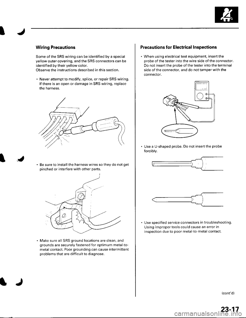
. Never attempt to modify. splice, or repair SRS wiring.
lf there is an open or damage in SRS wiring, replace
the harness.
Be sure to install the harness wires so they do not get
Dinched or interfere with other Darts.
Make sure all SRS ground locations are clean, and
grounds are securely fastened for optimum metal-to-
metal contact. Poor grounding can cause intermittent
problems that are difficult to diagnose.
Precautions for Electrical Inspections
. When using electricaltest equipment, insertthe
probe of the tester into the wire side of the connector.
Do not insert the probe of the tester into the terminal
side of the connector, and do not tamper with the
connector.
Use a U-shaped probe. Do not insert the probe
forcibly.
Use specified service connectors in tro u bleshooting.
Using improper tools cou ld cause an error in
inspection due to poor metal-to-metal contact.
(cont'd)
23-17
Page 1027 of 1139
sRs
Precautions and Procedures (cont'dl
Disconnecting System Connectors
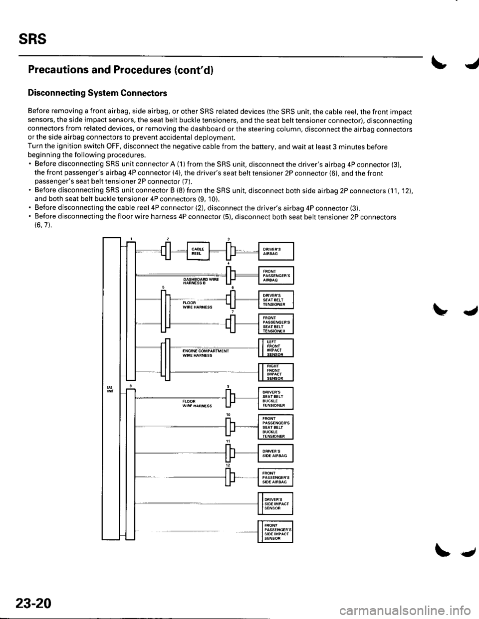
Before removing a front airbag. side airbag, or other SRS related devices {the SRS unit, the cable reel, the front impact
sensors, the side impact sensors, the seat belt buckle tensioners, and the seat belt tensioner connector), disconnectingconnectors from related devices, or removing the dashboard or the steering column, disconnect the airbag connectorsor the side airbag connectors to prevent accidental deploVment.
Turn the ignition switch OFF, disconnect the negative cable from the battery, and wait at least 3 minutes before
beginning the following procedures.'BeforedisconnectingSRSunitconnectorA(1)fromtheSRSunit,disconnectthedriver'sairbag4Pconnector(3).
the front passenger's airbag 4P connector (4), the driver's seat belt tensioner 2P connector (6), and the frontpassenger's seat belt tensioner 2P connector (7).
. Before disconnecting SRS unit connector B (8) from the SRS unit, disconnect both side airbag 2P connectors (11. '12),
and both seat belt buckle tensioner 4P connectors (9, 10).. Before disconnecting the cable reel 4P connector (2), disconnect the driver's airbag 4P connector (3).'Beforedisconnectingthefloorwireharness4Pconnector(5),disconnectbothseatbelttensioner2Pconnectors
(6.7).
23-20
\.
Page 1028 of 1139
1. Disconnect the battery negative cable, and wait at
least 3 minutes.
Driver's Airbag
2. Remove the access panel (A) from the steering
wheel, then disconnecl the driver's airbag 4P
connector (B)from the cable reer.
Front Passenger's Airbag
3. Disconnect the front passenger's airbag 4P
connector (A)from dashboard wire harness B.
Side Airbag
4. Disconnect both side airbag 2P connectors (Alfrom
the floor wire harness.
(cont'd)
23-21
Page 1029 of 1139
sRs
Precautions and Procedures (cont'd)
Seat Belt Tensioner
5. Disconnect both seat belt tensioner 2P connectors
(A) from the floor wire harness
Seat Belt Buckle Tensioner
6. Disconnect both seat belt buckle tensioner 4P
connectors (A).
23-22
\J
4
SRS Unit
7. Disconnect SRS unit connector A, SRS unit
connector B, and/or SRS unit connector C from the
SRS unit.
Page 1030 of 1139
General Troubleshooting Information
DTC (Diagnostic Trouble Codesl
The self-diagnostic function of the SRS system allows it
to locate the causes of system problems and then store
this information in memory. For easier troubleshooting,
this data can be retrieved via a data link circuit.
. When you turn the ignition switch ON (ll), the SRS
indicator will come on. lf it goes off after 6 seconds,
the system is normal.. lf there is an abnormality, the svstem locates and
defines the problem, stores this information in
memory, and turns the SRS indicator on. The data
will remain in the memory even when the ignition
switch is turned off or if the battery is disconnected.. When you connect the Honda PG lM Tester to the 16P
data link connector (DLC)to short the SCS terminal,
and turn the ignition switch ON (ll). the SRS indicator
will indicate the diagnostic trouble code (DTC) by the
number of blinks.. When you connect the Honda PGM Tester to the 16P
data link Connector (DLC), you can retrieve the DTC in
the Honda Systems "SRS" menu.. After reading and recording the DTC, proceed with
the troubleshooting procedure for th is code.
Precautions. Use only a digital multimeter to check the system. lf
it's not a Honda multimeter, make sure its output is
10 mA (0.01A) or less when switched to the smallest
value in the ohmmeter range, A tester with a higher
output could damage the airbag circuit or cause
accidental airbag deployment and possible injury.. Whenever the ignition switch is ON (ll), or has been
turned OFF for less than 3 minutes, be careful not to
bump the SRS uniU the airbags could accidentally
deploy and cause damage or injuries.. Before you remove the SRS harness, disconnect the
driver's airbag connector. the front passenger's
airbag connector, both side airbag connectors, both
seat belt buckle tensioner connectors, and both seat
belt tensioner connectors.. Make sure the battery is sufficiently charged. lf the
battery is dead or low, measuring values won't be
correct.. Do not touch a tester probe to the terminals in the
SRS unit or harness connectors, and do not connect
the terminals with a jumper wire. Use only the
backprobe set and the Honda PGM Tester. Backprobe
spring loaded lock type connectors correctly.
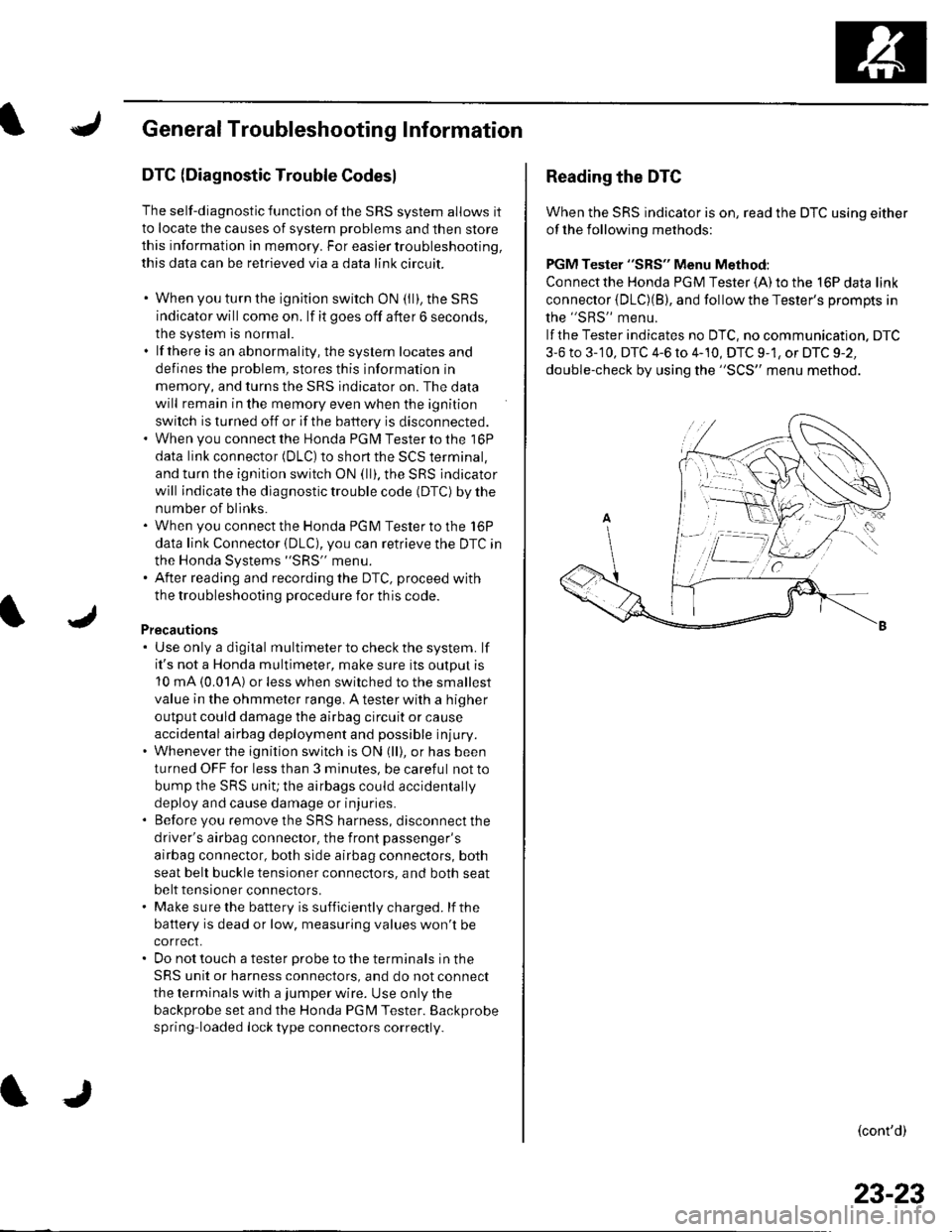
Reading the DTC
When the SRS indicator is on, read the DTC using either
of the following methods:
PGM Tester "SRS" Menu Method:
Connect the Honda PGM Tester {A) to the 16P data link
connector {DLC)(B), and follow the Tester's Drompts in
the "SRS" menu.
lf the Tester indicates no DTC, no communication. DTC
3-6 to 3-'10, DTC 4-6 to 4-10, DTC 9-1, or DTC 9-2,
double-check by using the "SCS" menu method.
(cont'd)
23-23
Page 1033 of 1139
sRs
General Troubleshooting Information (cont'dl
Erasing the DTG Memory
Specisl Tool Required
SCS service connector 07PAz-0010100
To erase the DTC(S)from the SRS unit, use a Honda
PGM Tester {see lhe Honda PGfM Tester SRS Vehicle
System Supplement) or the following procedure.
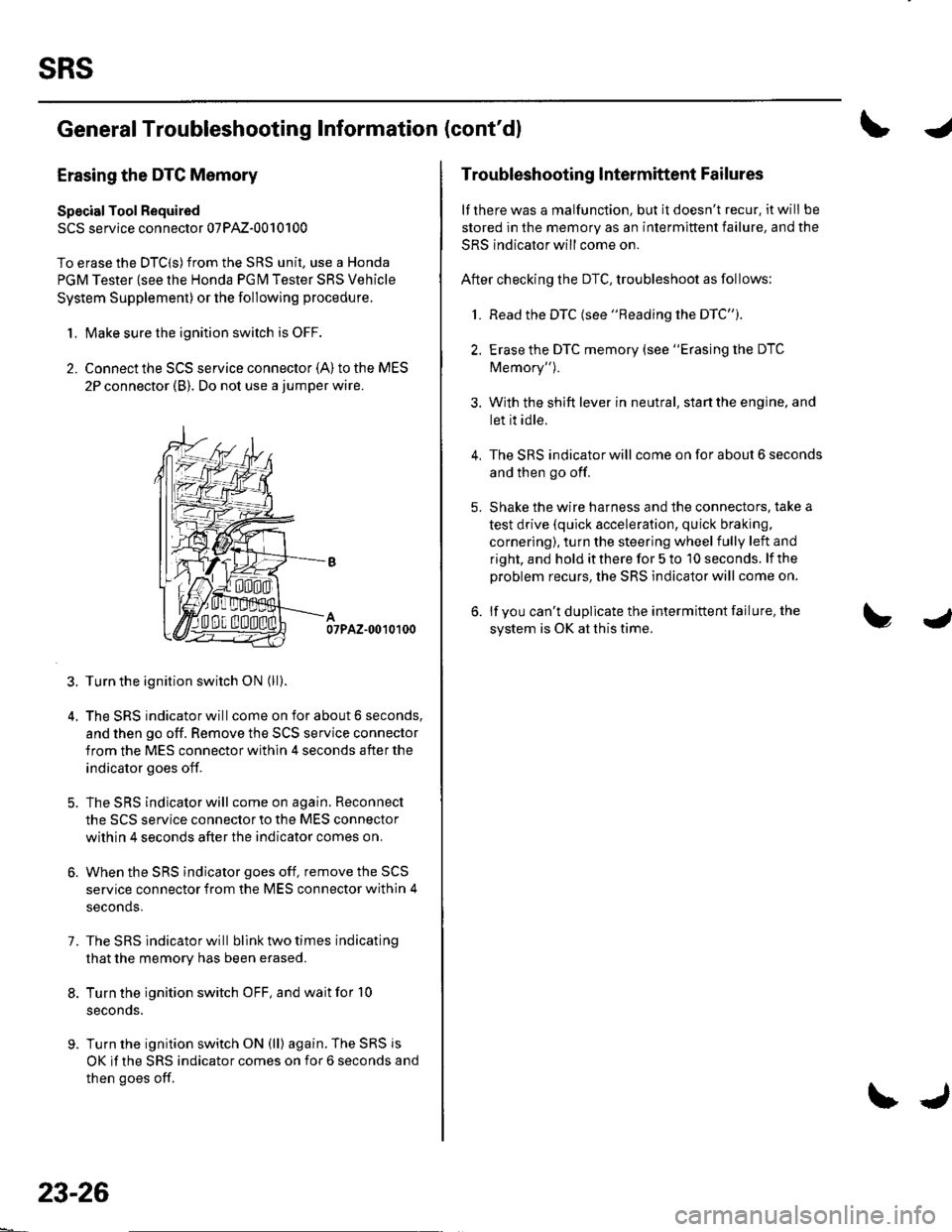
1. Make sure the ignition switch is OFF.
2. Connect the SCS service connector {A) to the MES
2P connector (B). Do not use a jumper wire.
07PAZ-0010100
3. Turn the ignition switch ON (ll).
4. The SRS indicator will come on for about 6 seconds,
and then go off. Remove the SCS service connector
from the MES connector within 4 seconds after the
indicator goes off.
5. The SRS indicator will come on again. Reconnect
the SCS service connector to the MES connector
within 4 seconds after the indicator comes on.
6. When the SRS indicator goes off, remove the SCS
service connector from the MES connector within 4
seconds.
7. The SRS indicator will bllnk two times indicating
that the memory has been erased.
8. Turn the ignition switch OFF, and wait for '10
seconds.
9. Turn the ignition switch ON (ll) again. The SRS js
OK if the SRS indicator comes on for 6 seconds and
then goes off.
23-26
\J
Troubleshooting lntermittent Failures
lf there was a malfunction, but it doesn't recur. it will be
stored in the memory as an intermittent failure, and the
SRS indicator will come on.
After checking the DTC, troubleshoot as follows:
1. Read the DTC (see "Reading the DTC").
2. Erase the DTC memory (see "Erasing the DTC
Memory").
3. With the shift lever in neutral, start the engine, and
let it idle.
The SRS indicator will come on for about 6 seconds
and then go off.
Shake the wire harness and the connectors. take a
test drive (quick acceleration, quick braking,
cornering), turn the steering wheel fully left and
right, and hold it there for 5 to '10 seconds. lf the
problem recurs, the SRS indicator will come on.
lf you can't duplicate the intermittent failure, the
system is OK at this time.
4.
Page 1043 of 1139
sRs
J
a
DTC Troubleshooting
DTC 1-1: Open in Driver's Airbag Inflator
DTC 1-2: Increased Resistance in Driver's
Airbag Inflator
Special Tools Required. SRS inflator simulator 07SAZ-TB4011A. SRS simulator lead F 07XAZ-S230100
1. Erase the DTC memory (see page 23-26).
2. Turn the ignition switch ON {ll), and check that the
SRS indicator comes on for aboul 6 seconds and
then goes off.
Does the SBS indicator stay on?
YES-Go to step 3.
NO Intermittent failure, system is OK at this time.
Go to Troubleshooting Intermittent Failures (see
page 23-26).
3. Turn the ignition switch OFF. Disconnect the
battery negative cable, and wait for 3 minutes.
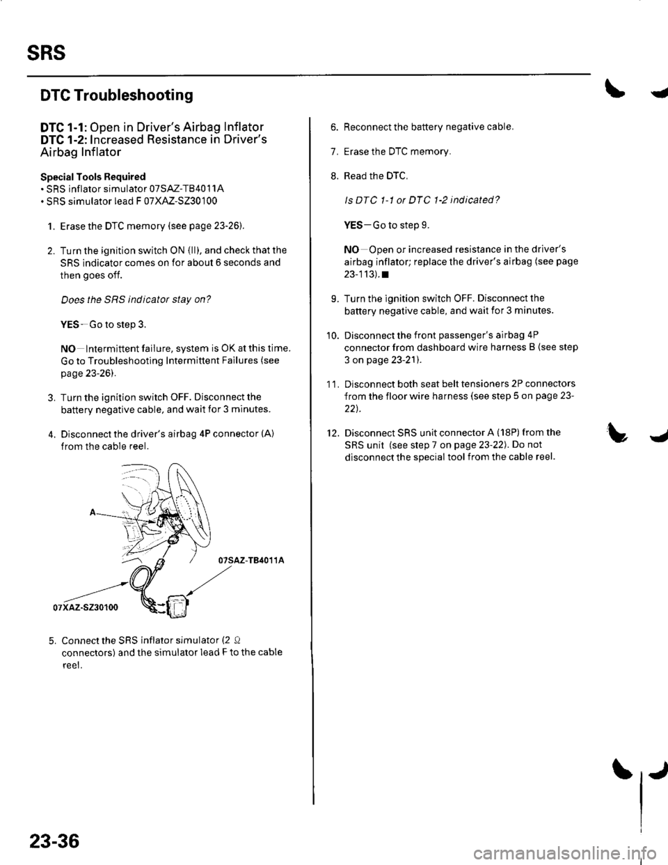
4. Disconnect the driver's airbag 4P connector (A)
from the cable reel.
07sAz-TB4011A
07xaz-s230100
5. Connect the SRS inflator simulator (2 Q
connectors) and the simulator lead F to the cable
reet.
23-36
6. Reconnect the battery negative cable.
7. Erase the DTC memory.
8. Read the DTC,
ls DTC 1-1 or DTC 1-2 indicated?
YES-Go to step 9.
NO Open or increased resistance in the driver's
airbag inflator; replace the driver's airbag (see page
23-113).t
9. Turn the ignition switch OFF. Disconnect the
battery negative cable, and wait ior 3 minutes.
10. Disconnect the front passenger's airbag 4P
connector from dashboard wire harness B (see step
3 on page 23-21).
1 1. Disconnect both seat belt tensioners 2P connectors
from the floor wire harness (see step 5 on page 23-
22t.
12. Disconnect SRS unit connector A (18P)from the
SRS unit (see step 7 on page 23-22). Do not
disconnect the special tool from the cable reel.
Page 1044 of 1139
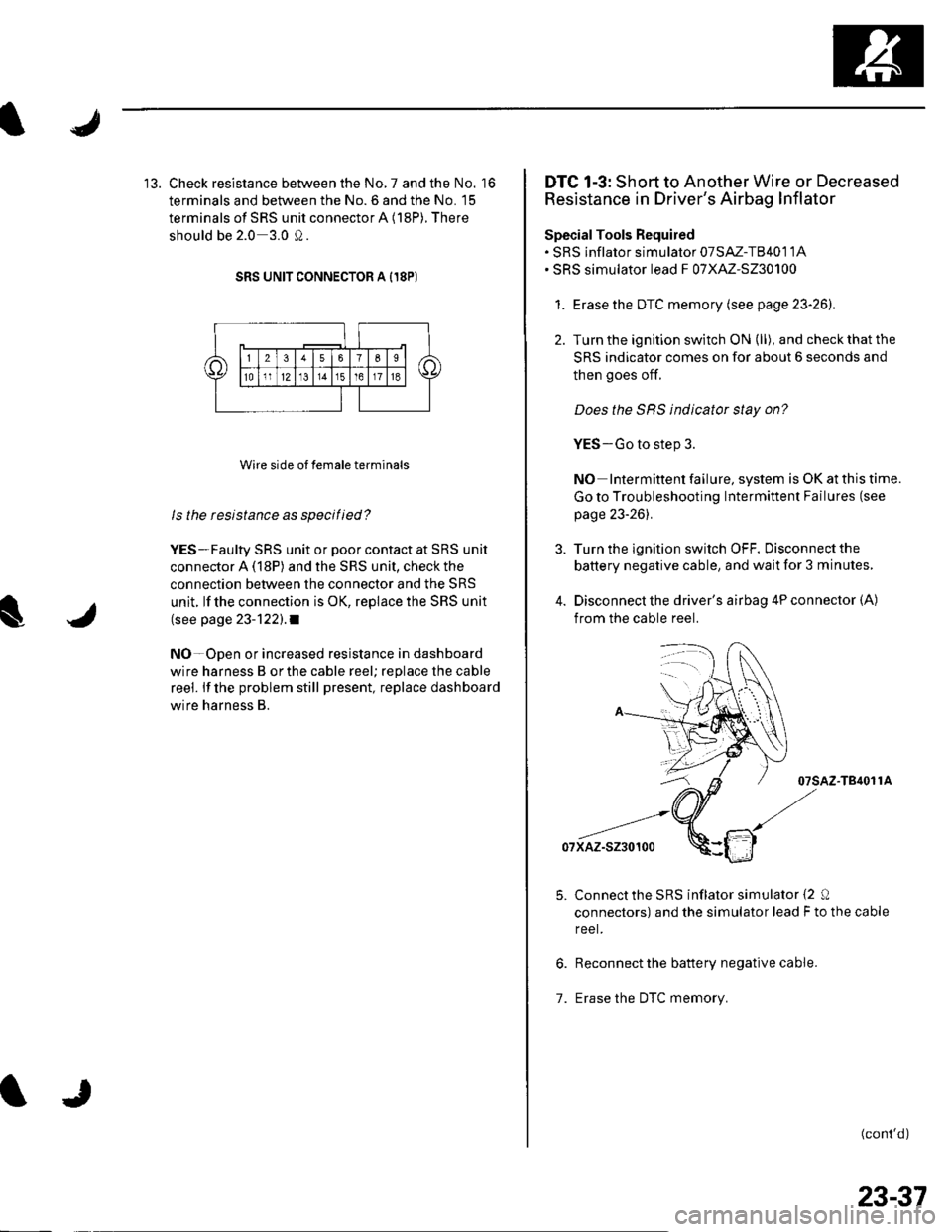
13. Check resistance between the No. 7 and the No. '16
terminals and between the No. 6 and the No. 15
terminals of SRS unit connector A (18P). There
should be 2.0 3.0 0.
SRS UNIT CONNECTOR A I18P)
Wire side of female terminals
ls the resistance as specilied?
YES-Faulty SRS unit or poor contact at SRS unit
connector A (18P) and the SRS unit, check the
connection between the connector and the SRS
unit. lf the connection is OK, replace the SRS unit
(see page 23-122).1
NO-Open or increased resistance in dashboard
wire harness B orthe cable reel; replace the cable
reel. lf the problem still present, replace dashboard
wire harness B.
DTC 1-3: Short to Another Wire or Decreased
Resistance in Driver's Airbag Inflator
SpecialTools Required. SRS inflator simulator 07SAZ-T8401 1A. SRS simulator lead F 07XAZ-S230100
1. Erasethe DTC memory (see page 23-26).
2. Turn the ignition switch ON (ll), and check that the
SRS indicator comes on for about 6 seconds and
then goes of{.
Does the SRS indicator stay on?
YES-Go to step 3.
NO Intermittent failure, system is OK at this time.
Go to Troubleshooting Intermittent Failures (see
page 23-261.
Turn the ignition switch OFF. Disconnect the
battery negative cable, and wait for 3 minutes,
Disconnect the driver's airbag 4P connector (A)
from the cable reel.
07sAz-T84011A
07xAz-s230100
Connectthe SRS inflator simulator {2 0
connectors) and the simulator lead F to the cable
reel.
Reconnect the battery negative cable.
Erase the DTC memory.1.
(cont'd)
23-37