Page 853 of 4378

9. Install the valve covers.
Valve Train Analysis— Engine Running, Camshaft Lobe Lift— Push Rod Engine
Check the lift of each lobe in consecutive order and make a note of the readings. 1. Remove the valve covers.
2. Remove the rocker arm seat bolts, rocker arm seat (6A528) and rocker arms.
Typical Engine With Push Rods
3. Make sure the valve tappet is seated against camshaft (6250). Install (1) Dial Indicator Gauge with Holding Fixture so the ball socket adapter of the indicator is on top of the valve tappet or (2)
Dial Indicator Gauge Adapter is on top of push rod and in same plane as valve tappet push rod
movement.
4. Remove the spark plugs.
5. Connect an auxiliary starter switch in the starting circuit. Crank the engine with ignition switch in OFF position. Bump crankshaft over until valve tappet is on base circle of camshaft lobe. At this
point, valve tappet will be in its lowest position. If checking during engine assembly, turn
crankshaft using a socket or ratchet.
6. Zero the dial indicator. Continue to rotate crankshaft slowly until valve tappet is in fully- raised
position (highest indicator reading).
7. NOTE: If lift on any lobe is below specified service limits, install a new camshaft, and new valve
tappets.
Remove the Dial Indicator with Holding Fixture, Dial Indicator Gauge Adapter, and auxiliary
starter switch.
8. Install rocker arm seats, rocker arms and rocker arm seat bolts.
9. Install valve covers.
10. Install spark plugs.
Valve Train Analysis— Engine Running, Valve Tappet
Valve tappet noise can be caused by any of the following:
�zexcessive valve tappet gap (collapsed) �K�l�j . 16 �b�a
172003 Mustang Workshop Manual
17. 11. 2011file:///C:/Ford/2000 - 2004/tsocache/SHEF_4464/S3B~us~en~ ...
Page 936 of 4378

Valve seat angle 44.75 degrees
Valve spring free length —
Valve spring squareness —
Valve spring compression pressure —
valve
open (without damper) 1000 N (224 lbs) @ 29.2 mm (1.16 in)
Valve spring compression pressure —
valve
closed (without damper) 350 N (79 lbs) @ 40.7 mm (1.62 in)
Valve spring installed height 40.7 mm (1.62 in)
Valve spring installed pressure —
Rocker arm ratio 1.73
Hydraulic Lash Adjuster
Diameter 22.195-
22.212 mm (0.8738- 0.8745 in) Clearance-
to-bore 0.018-
0.068 mm (0.0007- 0.0027 in) Service limit 0.127 mm (0.005 in)
Hydraulic leakdown rate a
Collapsed lash adjuster gap —
Camshaft
Theoretical valve lift @ 0 lash —
intake 11.30 mm (0.45 in)
Theoretical valve lift @ 0 lash —
exhaust 11.47 mm (0.45 in)
Lobe lift —
intake 6.53 mm (0.257 in)
Lobe lift —
exhaust 6.57 mm (0.259 in)
Allowable lobe lift loss 0.127 mm (0.005 in)
Journal diameter 52.082-
52.108 mm (2.0505- 2.0515 in) Camshaft journal bore inside diameter —
No. 1 55.689-
55.664 mm (2.192- 2.191 in) Camshaft journal bore inside diameter —
No. 2
and No. 3 55.308-
55.283 mm (2.177- 2.176 in) Camshaft journal bore inside diameter —
No. 4 55.684-
55.664 mm (2.192- 2.191 in) Camshaft journal-
to-bearing clearance 0.025-
0.076 mm (0.001- 0.003 in) Runout 0.05 mm (0.002 in) runout of No. 2 or No. 3
relative to No. 1 and No. 4 End play 0.025-
0.150 mm (0.001- 0.006 in) Cylinder Block
Cylinder bore diameter 96.813 mm (3.81 in)
Cylinder bore maximum taper 0.050 mm (0.002 in)
Cylinder bore maximum out-of-
round 0.050 mm (0.002 in)
Main bearing bore inside diameter 68.905 mm (2.713 in)
68.885 mm (2.712 in)
Camshaft bearing bore inside diameter —
intake 47.097 mm (1.8542 in) max. 47.072 mm (1.8532
in) min. Camshaft bearing bore inside diameter —
exhaust 39.739 mm (1.5645 in) max. 39.714 mm (1.5635
in) min. Head gasket surface flatness 0.08 mm (0.003 in) in 152.0 mm (6.00 in)
Crankshaft
Main bearing journal diameter 63.983-
64.003 mm (2.5190- 2.5198 in) �K�l�j . 2 �b�a
62003 Mustang Workshop Manual
17. 11. 2011file:///C:/Ford/2000 - 2004/tsocache/SHEF_4464/S3B~us~en~ ...
Page 1066 of 4378
DISASSEMBLY
Engine
1. Remove the bolts and the LH engine support insulator.
SECTION 303-
01A: Engine — 3.8L 2003 Mustang Workshop Manual Special Tool(s)
Service Set, Camshaft
303-
017 (T65L-6250- A) Remover, Crankshaft Vibration
Damper
303-
009 (T58P-6316- D) Lifting Bracket Set, Engine
303-
D095 (D94L-6001- A) or
equivalent Remover, Power Steering
Pump Pulley
211-
016 (T69L-10300- B) Remover, Oil Seal
303-
409 (T92C-6700- CH) Remover, Crankshaft Vibration
Damper
303-
176 (T82L-6316- B) �K�l�j . 1 �b�a
212003 Mustang Workshop Manual
17. 11. 2011file:///C:/Ford/2000 - 2004/tsocache/SHEF_4464/S3B~us~en~ ...
Page 1084 of 4378
Remove the four main bearing caps and lower crankshaft main bearings.
1. Remove the stud bolts.
2. Remove the main bearing cap and the lower crankshaft main bearing.
66. Repeat the main bearing cap and the lower bearing removal steps for the remaining main bearing caps and the crankshaft lower main bearings.
67. CAUTION: The crankshaft journals must be protected from damage when the
crankshaft is removed.
Remove the crankshaft and the crankshaft rear seal.
68. NOTE: For ease in assembly, record the location of the crankshaft upper thrust bearing.
Remove the crankshaft upper main bearings and the crankshaft upper thrust bearing.
69. Using the camshaft bearing service set, remove the camshaft bearings. �K�l�j . 19 �b�a
212003 Mustang Workshop Manual
17. 11. 2011file:///C:/Ford/2000 - 2004/tsocache/SHEF_4464/S3B~us~en~ ...
Page 1085 of 4378
70. Using the camshaft bearing service set, remove the engine dynamic balance shaft bearings.
71. If equipped, remove the engine block heater. For additional information, refer to
Section 303 -
03A .
72. NOTE: For cleaning purposes, the plugs should be removed.
If necessary, remove the following: 1. the cylinder block dowels.
2. the oil gallery plugs.
3. the water jacket plugs. �K�l�j . 20 �b�a
212003 Mustang Workshop Manual
17. 11. 2011file:///C:/Ford/2000 - 2004/tsocache/SHEF_4464/S3B~us~en~ ...
Page 1093 of 4378

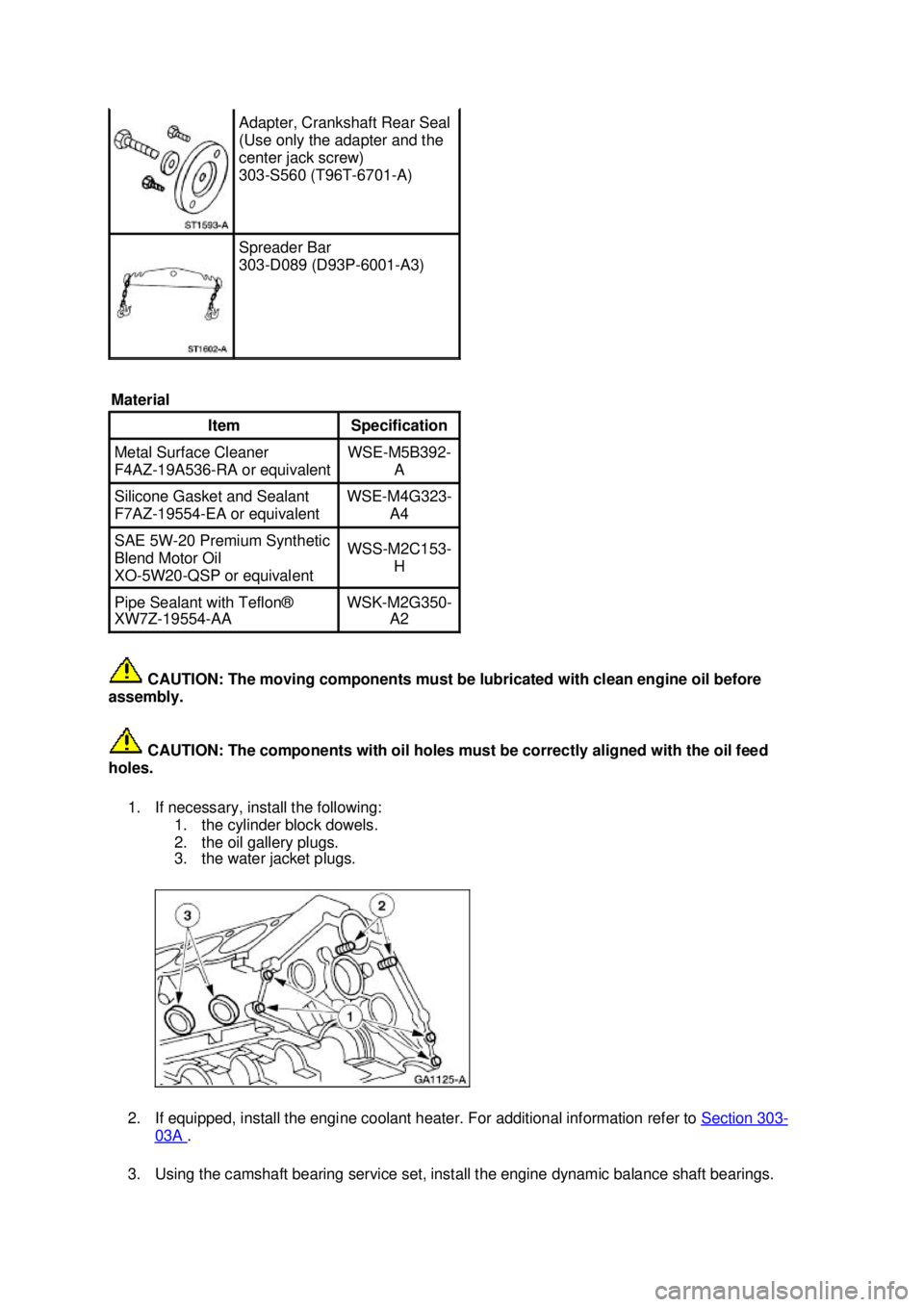
CAUTION: The moving components must be lubricated with clean engine oil before
assembly.
CAUTION: The components with oil holes must be correctly aligned with the oil feed
holes.
1. If necessary, install the following: 1. the cylinder block dowels.
2. the oil gallery plugs.
3. the water jacket plugs.
2. If equipped, install the engine coolant heater. For additional information refer to Section 303 -
03A .
3. Using the camshaft bearing service set, install the engine dynamic balance shaft bearings. Adapter, Crankshaft Rear Seal
(Use only the adapter and the
center jack screw)
303-
S560 (T96T-6701- A) Spreader Bar
303-
D089 (D93P-6001- A3)
Material Item Specification
Metal Surface Cleaner
F4AZ-
19A536- RA or equivalent WSE-
M5B392-
A Silicone Gasket and Sealant
F7AZ-
19554- EA or equivalent WSE-
M4G323-
A4 SAE 5W-
20 Premium Synthetic
Blend Motor Oil
XO- 5W20-QSP or equivalent WSS-
M2C153-
H Pipe Sealant with Teflon®
XW7Z-19554-
AA WSK-
M2G350-
A2 �K�l�j . 2 �b�a
282003 Mustang Workshop Manual
17. 11. 2011file:///C:/Ford/2000 - 2004/tsocache/SHEF_4464/S3B~us~en~ ...
Page 1094 of 4378
4. Using the camshaft bearing service set, install the camshaft bearings.
5. Install the following:
1. the engine dynamic balance shaft bearing cover.
2. the camshaft bearing cover.
6. CAUTION: Do not damage the camshaft lobes when installing the camshaft.
Install the camshaft and the camshaft spacer. �K�l�j . 3 �b�a
282003 Mustang Workshop Manual
17. 11. 2011file:///C:/Ford/2000 - 2004/tsocache/SHEF_4464/S3B~us~en~ ...
Page 1131 of 4378

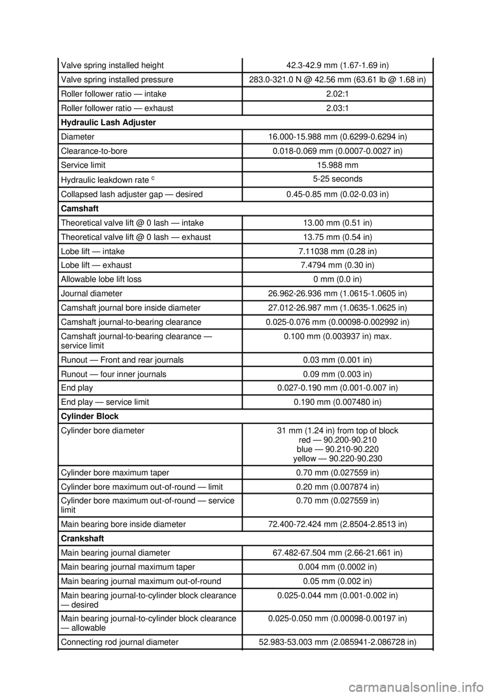
Valve spring installed height 42.3-
42.9 mm (1.67- 1.69 in) Valve spring installed pressure 283.0-
321.0 N @ 42.56 mm (63.61 lb @ 1.68 in) Roller follower ratio —
intake 2.02:1
Roller follower ratio —
exhaust 2.03:1
Hydraulic Lash Adjuster
Diameter 16.000-
15.988 mm (0.6299- 0.6294 in) Clearance-
to-bore 0.018-
0.069 mm (0.0007- 0.0027 in) Service limit 15.988 mm
Hydraulic leakdown rate
c 5-
25 seconds Collapsed lash adjuster gap —
desired 0.45-
0.85 mm (0.02- 0.03 in) Camshaft
Theoretical valve lift @ 0 lash —
intake 13.00 mm (0.51 in)
Theoretical valve lift @ 0 lash —
exhaust 13.75 mm (0.54 in)
Lobe lift —
intake 7.11038 mm (0.28 in)
Lobe lift —
exhaust 7.4794 mm (0.30 in)
Allowable lobe lift loss 0 mm (0.0 in)
Journal diameter 26.962-
26.936 mm (1.0615- 1.0605 in) Camshaft journal bore inside diameter 27.012-
26.987 mm (1.0635- 1.0625 in) Camshaft journal-
to-bearing clearance 0.025-
0.076 mm (0.00098- 0.002992 in) Camshaft journal-
to-bearing clearance —
service limit 0.100 mm (0.003937 in) max.
Runout —
Front and rear journals 0.03 mm (0.001 in)
Runout —
four inner journals 0.09 mm (0.003 in)
End play 0.027-
0.190 mm (0.001- 0.007 in) End play —
service limit 0.190 mm (0.007480 in)
Cylinder Block
Cylinder bore diameter 31 mm (1.24 in) from top of block
red — 90.200-90.210
blue — 90.210-90.220
yellow — 90.220-90.230 Cylinder bore maximum taper 0.70 mm (0.027559 in)
Cylinder bore maximum out-of-
round —limit 0.20 mm (0.007874 in)
Cylinder bore maximum out-of-
round —service
limit 0.70 mm (0.027559 in)
Main bearing bore inside diameter 72.400-
72.424 mm (2.8504- 2.8513 in) Crankshaft
Main bearing journal diameter 67.482-
67.504 mm (2.66- 21.661 in) Main bearing journal maximum taper 0.004 mm (0.0002 in)
Main bearing journal maximum out-of-
round 0.05 mm (0.002 in)
Main bearing journal-
to-cylinder block clearance
— desired 0.025-
0.044 mm (0.001- 0.002 in) Main bearing journal-
to-cylinder block clearance
— allowable 0.025-
0.050 mm (0.00098- 0.00197 in) Connecting rod journal diameter 52.983-
53.003 mm (2.085941- 2.086728 in) �K�l�j . 2 �b�a
62003 Mustang Workshop Manual
17. 11. 2011file:///C:/Ford/2000 - 2004/tsocache/SHEF_4464/S3B~us~en~ ...