Page 777 of 4378

4 N805572-
S36 Air bag module retaining screws (2 req'd)
5 3L518 Steering wheel spoke cover
(2 req'd)
6 — Lock tabs
7 14A664 Clockspring
8 13318 Turn indicator cancel cam
9 3C610 Snap ring
10 3520 Bearing spring
11 3518 Upper bearing sleeve
12 3517 Upper bearing (small)
13 3517 Lower bearing (large)
14 3524 Shaft assembly
15 390345-
S36 Screw
16 13K359 Multi-
function switch 17 3E695 Lock cam
18 3F609 Tilt wheel handle
19 N806157 Lock cam pivot pin
20 3530 Lower shroud
21 55929 Shroud retaining screws
22 3D544 Release lever
23 3B661 Lock actuator lever (RH)
24 N805856 Lock actuator lever pin
25 3D653 Lock actuator lever (LH)
26 3B664 Lock lever spring (2 req'd)
27 14A099 Wiring shield
28 3D655 Lock lever spring return
29 3E715 Lock lever upper actuator
30 3E696 Lock spring (shaft)
31 11572 Ignition switch
32 N806423-
S56 Steering column mounting lower nuts
33 N806584 Screw
34 3E660 Mounting bracket
35 3D681 Bearing retaining
36 3518 Bearing sleeve
37 3517 Lower bearing
38 3L539 Lower bearing tolerance ring
39 3C131 Sensor ring
40 3520 Bearing spring
41 N808349 Bolt —
flange yoke 42 3N725 Coupling
43 3C611 Tube boot
44 3B676 Intermediate shaft �K�l�j . 2 �b�a
42003 Mustang Workshop Manual
17. 11. 2011file:///C:/Ford/2000 - 2004/tsocache/SHEF_4464/S3B~us~en~ ...
Page 2037 of 4378

DIAGNOSIS AND TESTING
Starting System
Refer to Wiring Diagrams Cell
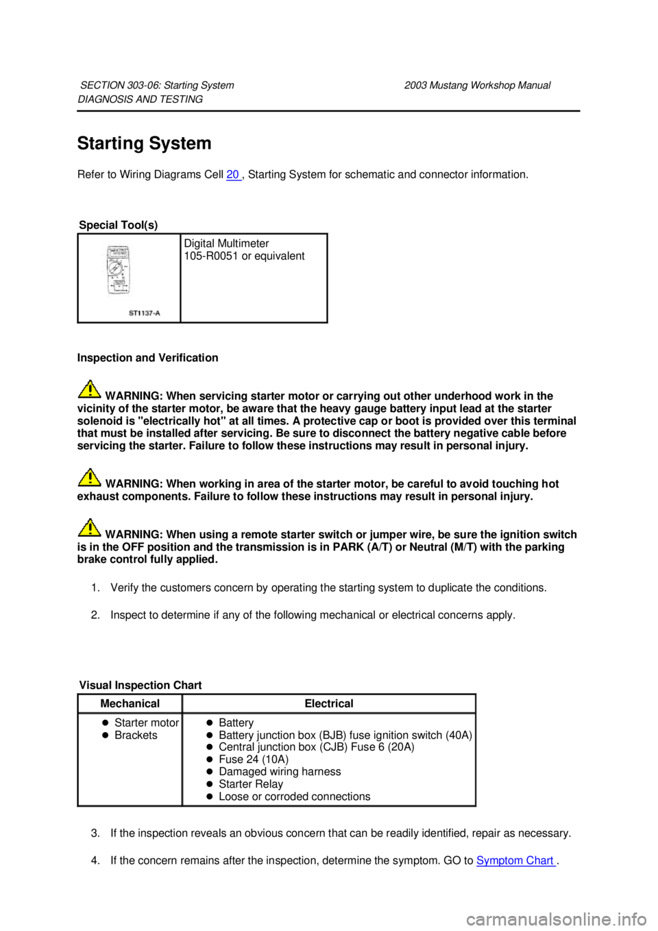
20 , Starting System for schematic and connector information.
Inspection and Verification WARNING: When servicing starter motor or carrying out other underhood work in the
vicinity of the starter motor, be aware that the heavy gauge battery input lead at the starter
solenoid is "electrically hot" at all times. A protective cap or boot is provided over this terminal
that must be installed after servicing. Be sure to disconnect the battery negative cable before
servicing the starter. Failure to follow these instructions may result in personal injury.
WARNING: When working in area of the starter motor, be careful to avoid touching hot
exhaust components. Failure to follow these instructions may result in personal injury.
WARNING: When using a remote starter switch or jumper wire, be sure the ignition switch
is in the OFF position and the transmission is in PARK (A/T) or Neutral (M/T) with the parking
brake control fully applied.
1. Verify the customers concern by operating the starting system to duplicate the conditions.
2. Inspect to determine if any of the following mechanical or electrical concerns apply.
3. If the inspection reveals an obvious concern that can be readily identified, repair as necessary.
4. If the concern remains after the inspection, determine the symptom. GO to Symptom Chart .
SECTION 303-
06: Starting System 2003 Mustang Workshop Manual Special Tool(s)
Digital Multimeter
105-
R0051 or equivalent Visual Inspection Chart
Mechanical Electrical
�z
Starter motor
�z Brackets �z
Battery
�z Battery junction box (BJB) fuse ignition switch (40A)
�z Central junction box (CJB) Fuse 6 (20A)
�z Fuse 24 (10A)
�z Damaged wiring harness
�z Starter Relay
�z Loose or corroded connections �K�l�j . 1 �b�a
112003 Mustang Workshop Manual
18. 11. 2011file:///C:/Ford/2000 - 2004/tsocache/SHEF_4464/S3B~us~en~ ...
Page 2044 of 4378

Component Tests
Starter Motor —Voltage Drop Test
WARNING: When servicing starter motor or carrying out other underhood work in the
vicinity of the starter motor, be aware that the heavy gauge battery input lead at the starter
solenoid is "electrically hot" at all times. A protective cap or boot is provided over this terminal
that must be installed after servicing. Be sure to disconnect the battery negative cable before
servicing the starter. Failure to follow these instructions may result in personal injury.
WARNING: When using a remote starter switch or jumper wire, be sure the ignition switch
is in the OFF position and the transmission is in PARK (A/T) or Neutral (M/T) with the parking
brake control fully applied.
Always make the Digital Multimeter connections at the component terminal rather than at the wiring
end connector. Making a connection at the wiring end connector could result in false readings because
the meter will not pick up a high resistance between the wiring connector and the component.
Starter Motor— Motor Feed Circuit
1. Make sure the battery is fully charged. Perform a battery load test. For additional information, refer to Section 414 - 00 .
2. Disconnect the inertia fuel shut off (IFS) switch.
3. Connect a remote starter switch between the starter solenoid S- terminal and the battery positive
(+) terminal.
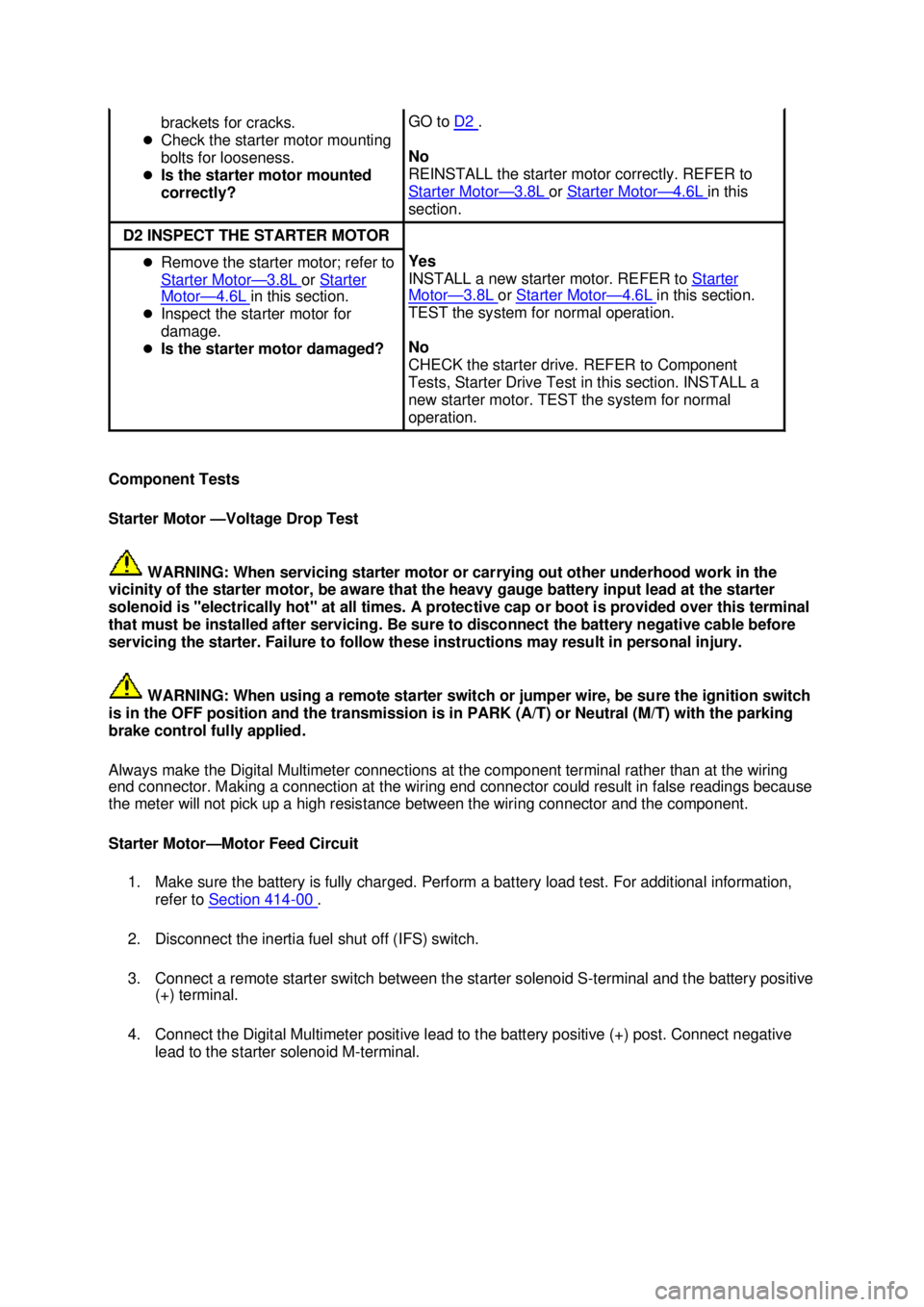
4. Connect the Digital Multimeter positive lead to the battery positive (+) post. Connect negative lead to the starter solenoid M- terminal. brackets for cracks.
�z Check the starter motor mounting
bolts for looseness.
�z Is the starter motor mounted
correctly? GO to
D2 .
No
REINSTALL the starter motor correctly. REFER to
Starter Motor — 3.8L or
Starter Motor — 4.6L in this
section. D2 INSPECT THE STARTER MOTOR
�z
Remove the starter motor; refer to
Starter Motor — 3.8L or
Starter Motor — 4.6L in this section.
�z Inspect the starter motor for
damage.
�z Is the starter motor damaged? Yes
INSTALL a new starter motor. REFER to
Starter Motor — 3.8L or
Starter Motor — 4.6L in this section.
TEST the system for normal operation.
No
CHECK the starter drive. REFER to Component
Tests, Starter Drive Test in this section. INSTALL a
new starter motor. TEST the system for normal
operation. �K�l�j . 8 �b�a
112003 Mustang Workshop Manual
18. 11. 2011file:///C:/Ford/2000 - 2004/tsocache/SHEF_4464/S3B~us~en~ ...
Page 2052 of 4378

REMOVAL AND INSTALLATION
Starter Motor —
3.8L
Removal
WARNING: When servicing starter motor (11002) or carrying out other underhood work in
the vicinity of the starter motor, be aware that the heavy gauge battery input lead at the starter
solenoid (11390) is "electrically hot" at all times. A protective cap or boot is provided over this
terminal that must be installed after servicing. Be sure to disconnect the battery negative cable
before servicing the starter. Failure to follow these instructions may result in personal injury.
WARNING: When working in area of the starter motor, be careful to avoid touching hot
exhaust components. Failure to follow these instructions may result in personal injury.
NOTE: When working on the starter system, make sure the anti- theft system is deactivated (if
equipped.)
1. Disconnect the battery ground cable. For additional information, refer to Section 414 - 01 .
2. Raise and support the vehicle. For additional information, refer to Section 100 - 02 .
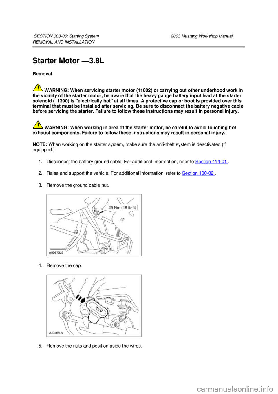
3. Remove the ground cable nut.
4. Remove the cap.
5. Remove the nuts and position aside the wires.
SECTION 303-
06: Starting System 2003 Mustang Workshop Manual �K�l�j . 1 �b�a
22003 Mustang Workshop Manual
18. 11. 2011file:///C:/Ford/2000 - 2004/tsocache/SHEF_4464/S3B~us~en~ ...
Page 2054 of 4378

REMOVAL AND INSTALLATION
Starter Motor —
4.6L
Removal
WARNING: When servicing starter motor (11002) or carrying out other underhood work in
the vicinity of the starter motor, be aware that the heavy gauge battery input lead at the starter
solenoid (11390) is "electrically hot" at all times. A protective cap or boot is provided over this
terminal that must be installed after servicing. Be sure to disconnect the battery negative cable
before servicing the starter. Failure to follow these instructions can result in personal injury.
WARNING: When working in area of the starter motor, be careful to avoid touching hot
exhaust components. Failure to follow these instructions can result in personal injury.
NOTE: When working on the starter system, make sure the anti- theft system is deactivated (if
equipped.)
1. Disconnect the battery ground cable. For additional information, refer to Section 414 - 01 .
2. Raise and support the vehicle. For additional information, refer to Section 100 - 02 .
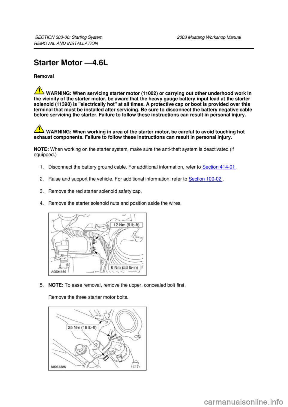
3. Remove the red starter solenoid safety cap.
4. Remove the starter solenoid nuts and position aside the wires.
5. NOTE: To ease removal, remove the upper, concealed bolt first.
Remove the three starter motor bolts.
SECTION 303-
06: Starting System 2003 Mustang Workshop Manual �K�l�j . 1 �b�a
32003 Mustang Workshop Manual
18. 11. 2011file:///C:/Ford/2000 - 2004/tsocache/SHEF_4464/S3B~us~en~ ...
Page 2062 of 4378
5. Remove the bolts and the ignition coil (12029).
6.
NOTE: Apply silicone brake caliper grease and dielectric compound to the inside of the spark
plug wire coil boot.
NOTE: Be sure to reinstall the radio ignition interference capacitor (18801) under the correct
mounting bolt.
To install, reverse the removal procedure. �K�l�j . 2 �b�a
22003 Mustang Workshop Manual
18. 11. 2011file:///C:/Ford/2000 - 2004/tsocache/SHEF_4464/S3B~us~en~ ...
Page 2063 of 4378
REMOVAL AND INSTALLATION
Spark Plug Wire
Removal and Installation
CAUTION: It is important to twist the spark plug wire boots while pulling upward to avoid
possible damage to the spark plug wire.
CAUTION: Spark plug wires must be connected to the correct ignition coil terminal. Mark
spark plug wire (12286) locations before removing them.
1. Using the special tool, remove the spark plug wire from the spark plug using a twisting motion.
2. Twist while pulling upward to disconnect the spark plug wires from the ignition coil (12029).
SECTION 303-
07A: Engine Ignition — 3.8L 2003 Mustang Workshop Manual Special Tool(s)
Remover, Spark Plug Wire
303-
106 (T74P- 6666A)
Material Item Specification
Silicone Brake Caliper Grease
and Dielectric Compound
D7AZ-
19A331-A or equivalent ESE-
M1C171-
A �K�l�j . 1 �b�a
22003 Mustang Workshop Manual
18. 11. 2011file:///C:/Ford/2000 - 2004/tsocache/SHEF_4464/S3B~us~en~ ...
Page 2064 of 4378
3.
CAUTION: Be sure to orient the spark plug boots so the spark plug wires do not
contact the exhaust manifold.
NOTE: Apply silicone brake caliper grease and dielectric compound to the inside of spark plug
and ignition coil boots of the spark plug wire.
To install, reverse the removal procedure. �K�l�j . 2 �b�a
22003 Mustang Workshop Manual
18. 11. 2011file:///C:/Ford/2000 - 2004/tsocache/SHEF_4464/S3B~us~en~ ...