Page 759 of 4378
REMOVAL AND INSTALLATION
Pulley —
CIII Pump
Removal 1. Remove the drive belt. For additional information, refer to Section 303 - 05 .
2. Raise and support the vehicle. For additional information, refer to Section 100 - 02 .
3. Using the special tool, remove the pulley. zInspect the pulley for paint marks in the web area near the hub. If there are two paint
marks, discard and install a new pulley. If there is no paint or one paint mark, use a paint
pencil to mark the web area of the pulley near the hub.
Installation 1. Using the special tool, install a new pulley.
SECTION 211-
02: Power Steering 2003 Mustang Workshop Manual Special Tool(s)
Pump Pulley Replacer
211-
185 (T91P-3A733- A) Pump Pulley Remover
211-
016 (T69L-10300- B) �K�l�j . 1 �b�a
22003 Mustang Workshop Manual
17. 11. 2011file:///C:/Ford/2000 - 2004/tsocache/SHEF_4464/S3B~us~en~ ...
Page 761 of 4378
REMOVAL AND INSTALLATION
Hose
Removal and Installation
CAUTION: While servicing the power steering system, make sure to plug all open hoses,
line fittings, and fluid ports to prevent the entry of contaminants or premature failure of the
power steering components can result.
1. Refer to the System View illustration in Description and Operation for the hose routing and retention points.
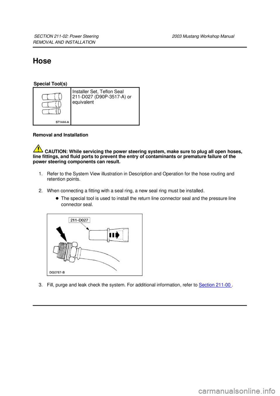
2. When connecting a fitting with a seal ring, a new seal ring must be installed. zThe special tool is used to install the return line connector seal and the pressure line
connector seal.
3. Fill, purge and leak check the system. For additional information, refer to Section 211 - 00 .
SECTION 211-
02: Power Steering 2003 Mustang Workshop Manual Special Tool(s)
Installer Set, Teflon Seal
211-
D027 (D90P-3517- A) or
equivalent �K�l�j . 1 �b�a
22003 Mustang Workshop Manual
17. 11. 2011file:///C:/Ford/2000 - 2004/tsocache/SHEF_4464/S3B~us~en~ ...
Page 763 of 4378
REMOVAL AND INSTALLATION
Cooler —
Fluid
Removal 1. Raise and support the vehicle. For additional information, refer to Section 100 - 02 .
2. Disconnect the power steering hoses.
3. Remove the bolt and routing bracket.
4. Remove the bolts and the power steering fluid cooler.
Installation 1. To install, reverse the removal procedure.
2. Fill and leak check the power steering system. For additional information, refer to Section 211 -SECTION 211-
02: Power Steering 2003 Mustang Workshop Manual �K�l�j . 1 �b�a
22003 Mustang Workshop Manual
17. 11. 2011file:///C:/Ford/2000 - 2004/tsocache/SHEF_4464/S3B~us~en~ ...
Page 765 of 4378
REMOVAL AND INSTALLATION
Gear
Removal
1. Turn the steering wheel as necessary to position the wheels in the straight- ahead position. Do
not lock the steering column.
2. Raise and support the vehicle. For additional information, refer to Section 100 - 02 .
3. Remove the front wheels and tires. For additional information, refer to Section 204 - 04 .
4. Remove the cotter pin and nut. Discard the cotter pin.
5. Using the special tool, disconnect the tie- rod end.
SECTION 211-
02: Power Steering 2003 Mustang Workshop Manual Special Tool(s)
Teflon Seal Replacer Set
211-
D027 (D90P-3517- A) or
Equivalent Tie Rod End Remover
211-
001 (TOOL- 3290-D) �K�l�j . 1 �b�a
42003 Mustang Workshop Manual
17. 11. 2011file:///C:/Ford/2000 - 2004/tsocache/SHEF_4464/S3B~us~en~ ...
Page 769 of 4378

DISASSEMBLY AND ASSEMBLY
Gear
Disassembly
NOTE:
The steering gear is serviceable as either a long or short rack assembly. This procedure covers
the removal and installation of the components not supplied with a short rack assembly. On short rack
assembly only the front wheel spindle tie- rods and front suspension steering ball stud dust seals are
serviced separately.
All steering gears
1. Remove the steering gear mounting bracket housing insulators. zDiscard worn or damaged steering gear mounting bracket housing insulators.
SECTION 211-
02: Power Steering 2003 Mustang Workshop Manual Special Tool(s)
Head Mounting Fixture
303-
D041 (D83L-500- B1) or
Equivalent Inner Tie Rod Socket Tool
211-
D025 (D90P-3290- A) or
Equivalent Steering Gear Holding Fixture
211-
D011 (D87P-3504- B) or
Equivalent
Material Item Specification
Multi-
Purpose Grease
XG- 4 ESR-
M1C159-
A Silicone Brake Caliper Grease
and Dielectric Compound
D7AZ-
19A331- A ESE-
M1C171-
A �K�l�j . 1 �b�a
62003 Mustang Workshop Manual
17. 11. 2011file:///C:/Ford/2000 - 2004/tsocache/SHEF_4464/S3B~us~en~ ...
Page 775 of 4378
SPECIFICATIONS
SECTION 211-
04: Steering Column 2003 Mustang Workshop Manual General Specifications
Item Specification
Lubricant
Ignition Lock Grease FOAZ-19584-
A ESA-
M1C232- A
Torque Specifications Description Nm lb-
ft lb-
in Lock cylinder housing screws 22 17 —
Steering column lower bearing retainer bolts 9 — 80
Ignition switch screws 6 — 53
Multi-
function switch screws 3 — 27
Steering wheel bolt 38 28 —
Steering column retaining nuts 15 12 —
Intermediate shaft coupler-
to-steering column shaft bolt 25 19 — �K�l�j . 1 �b�a
12003 Mustang Workshop Manual
17. 11. 2011file:///C:/Ford/2000 - 2004/tsocache/SHEF_4464/S3B~us~en~ ...
Page 776 of 4378
DESCRIPTION AND OPERATION
Steering Column
SECTION 211-
04: Steering Column 2003 Mustang Workshop Manual Item Part Number Description
1 043B13 Driver air bag module
2 N804385-
S100 Steering wheel bolt
3 3600 Steering wheel �K�l�j . 1 �b�a
42003 Mustang Workshop Manual
17. 11. 2011file:///C:/Ford/2000 - 2004/tsocache/SHEF_4464/S3B~us~en~ ...
Page 780 of 4378

GENERAL PROCEDURES
Supplemental Restraint System (SRS) Deactivation and
Reactivation
Deactivation
WARNING: Always wear safety glasses when repairing an air bag supplemental restraint
system (SRS) vehicle and when handling an air bag module. This will reduce the risk of injury
in the event of an accidental deployment.
WARNING: After deployment, the air bag surface can contain deposits of sodium
hydroxide, a product of the gas generant combustion that is irritating to the skin. Wash your
hands with soap and water afterwards.
WARNING: Never probe the connectors on the air bag module. Doing so can result in air
bag deployment, which can result in personal injury.
WARNING: Air bag modules with discolored or damaged trim covers must be installed
new, not repainted.
WARNING: The restraint system diagnostic tool is for restraint system service only.
Remove from vehicle prior to road use. Failure to remove could result in injury and possible
violation of vehicle safety standards.
1. WARNING: To avoid accidental deployment and possible personal injury, the
backup power supply must be depleted before repairing or replacing any front or side air
bag supplemental restraint system (SRS) components and before servicing, replacing,
adjusting or striking components near the front or side air bag sensors, such as doors,
instrument panel, console, door latches, strikers, seats and hood latches.
Please refer to the appropriate vehicle shop manual to determine location of the front air
bag sensors.
The side air bag sensors are located at or near the base of the B- pillar.
To deplete the backup power supply energy, disconnect the battery ground cable and
wait at least one minute. Be sure to disconnect auxiliary batteries and power supplies (if equipped). SECTION 211-
04: Steering Column 2003 Mustang Workshop Manual Special Tool(s)
Diagnostic Tool, Restraint
System (2 Req'd)
418-
F088 (105- R0012) �K�l�j . 1 �b�a
62003 Mustang Workshop Manual
17. 11. 2011file:///C:/Ford/2000 - 2004/tsocache/SHEF_4464/S3B~us~en~ ...