Page 1200 of 4378

IN-
VEHICLE REPAIR
Valve Seals
Removal and Installation 1. Remove the roller followers. For additional information, refer to Camshaft Roller Follower in this
section.
2. Remove the spark plug (12405) from the applicable cylinder.
3. Position the piston (6102) of the cylinder being serviced at the bottom of the stroke.
4. CAUTION: If air pressure has forced the piston to the bottom of the cylinder, any
loss of air pressure will allow the valve to fall into the cylinder. If air pressure must be
removed, support the valve prior to removal.
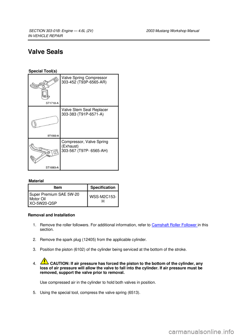
Use compressed air in the cylinder to hold both valves in position. 5. Using the special tool, compress the valve spring (6513). SECTION 303-
01B: Engine — 4.6L (2V) 2003 Mustang Workshop Manual Special Tool(s)
Valve Spring Compressor
303-
452 (T93P-6565- AR) Valve Stem Seal Replacer
303-
383 (T91P-6571- A) Compressor, Valve Spring
(Exhaust)
303-
567 (T97P- 6565- AH)
Material Item Specification
Super Premium SAE 5W-20
Motor Oil
XO- 5W20- QSP WSS-
M2C153-
H �K�l�j . 1 �b�a
22003 Mustang Workshop Manual
17. 11. 2011file:///C:/Ford/2000 - 2004/tsocache/SHEF_4464/S3B~us~en~ ...
Page 1214 of 4378
IN-
VEHICLE REPAIR
Oil Filter Adapter
Removal and Installation 1. Drain the cooling system. For additional information, refer to Section 303 - 03A or
Section 303 -
03B .
2. Disconnect the lower radiator hose.
3. Raise and support the vehicle. For additional information, refer to Section 100 - 02 .
4. Drain the engine oil.
5. Disconnect the oil pressure sensor electrical connector.
SECTION 303-
01B: Engine — 4.6L (2V) 2003 Mustang Workshop Manual Material
Item Specification
Super Premium SAE 5W-20
Motor Oil
XO- 5W20 QSP or equivalent WSS-
M2C153-
H Premium Engine Coolant
VC-
4A (In Canada CXC- 10; In
Oregon VC- 5) or equivalent ESE-
M97B44-
A �K�l�j . 1 �b�a
32003 Mustang Workshop Manual
17. 11. 2011file:///C:/Ford/2000 - 2004/tsocache/SHEF_4464/S3B~us~en~ ...
Page 1245 of 4378
14. Disconnect the vacuum line from the fuel pressure sensor. Item Part Number Description
1 — To crankshaft position sensor
2 — To A/C compressor
3 — To radio ignition interference capacitor (2)
4 — To fuel injectors (8)
5 — To ignition coils (8)
6 — To engine coolant temperature sensor
7 — To throttle position sensor
8 — To idle air control valve
9 — To EGR vacuum regulator
10 — To differential pressure feedback EGR
11 — To fuel pressure regulator
12 — Fuel injection ground
13 — To generator
14 — To camshaft position sensor
15 — To body
16 — To heated oxygen sensor (2)
17 — Engine bulkhead connector
18 — To low coolant sensor
19 — To body
20 — To power distribution box
21 — To body �K�l�j . 5 �b�a
212003 Mustang Workshop Manual
17. 11. 2011file:///C:/Ford/2000 - 2004/tsocache/SHEF_4464/S3B~us~en~ ...
Page 1260 of 4378

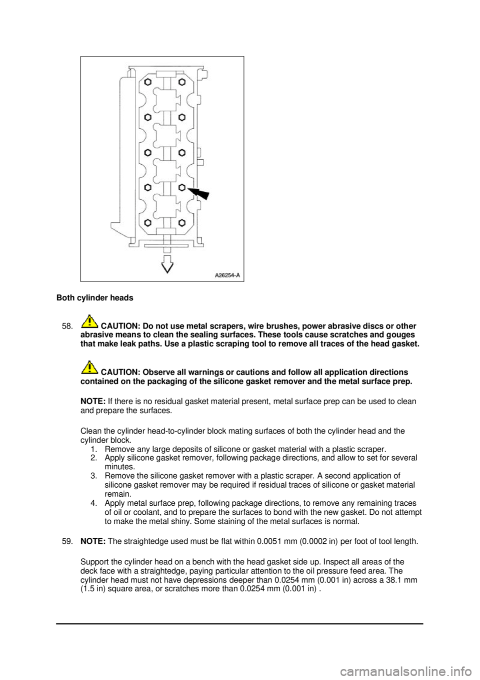
Both cylinder heads
58. CAUTION: Do not use metal scrapers, wire brushes, power abrasive discs or other
abrasive means to clean the sealing surfaces. These tools cause scratches and gouges
that make leak paths. Use a plastic scraping tool to remove all traces of the head gasket.
CAUTION: Observe all warnings or cautions and follow all application directions
contained on the packaging of the silicone gasket remover and the metal surface prep.
NOTE: If there is no residual gasket material present, metal surface prep can be used to clean
and prepare the surfaces.
Clean the cylinder head- to-cylinder block mating surfaces of both the cylinder head and the
cylinder block. 1. Remove any large deposits of silicone or gasket material with a plastic scraper.
2. Apply silicone gasket remover, following package directions, and allow to set for several minutes.
3. Remove the silicone gasket remover with a plastic scraper. A second application of silicone gasket remover may be required if residual traces of silicone or gasket material
remain.
4. Apply metal surface prep, following package directions, to remove any remaining traces of oil or coolant, and to prepare the surfaces to bond with the new gasket. Do not attempt
to make the metal shiny. Some staining of the metal surfaces is normal.
59. NOTE: The straightedge used must be flat within 0.0051 mm (0.0002 in) per foot of tool length.
Support the cylinder head on a bench with the head gasket side up. Inspect all areas of the
deck face with a straightedge, paying particular attention to the oil pressure feed area. The
cylinder head must not have depressions deeper than 0.0254 mm (0.001 in) across a 38.1 mm
(1.5 in) square area, or scratches more than 0.0254 mm (0.001 in) . �K�l�j . 20 �b�a
212003 Mustang Workshop Manual
17. 11. 2011file:///C:/Ford/2000 - 2004/tsocache/SHEF_4464/S3B~us~en~ ...
Page 1279 of 4378
16. Disconnect the vacuum line to the fuel pressure sensor. Item Part Number Description
1 — To crankshaft position sensor
2 — To A/C compressor
3 — To radio ignition interference capacitor (2)
4 — To fuel injectors (8)
5 — To ignition coils (8)
6 — To engine coolant temperature sensor
7 — To throttle position sensor
8 — To idle air control valve
9 — To EGR vacuum regulator
10 — To differential pressure feedback EGR
11 — To fuel pressure regulator
12 — Fuel injection ground
13 — To generator
14 — To camshaft position sensor
15 — To body
16 — To heated oxygen sensor (2)
17 — Engine bulkhead connector
18 — To low coolant sensor
19 — To body
20 — To power distribution box
21 — To body �K�l�j . 6 �b�a
242003 Mustang Workshop Manual
17. 11. 2011file:///C:/Ford/2000 - 2004/tsocache/SHEF_4464/S3B~us~en~ ...
Page 1338 of 4378
96. Install the RH and LH special tools.
97. Using the special tool, remove the engine from the stand.
98. Using the special tool, install the crankshaft rear main seal.
�zLubricate the oil seal using clean engine oil. 5 — To ignition coils (8)
6 — To engine coolant temperature sensor
7 — To throttle position sensor
8 — To idle air control valve
9 — To EGR vacuum regulator
10 — To differential pressure feedback EGR
11 — To fuel pressure regulator
12 — Fuel injection ground
13 — To generator
14 — To camshaft position sensor
15 — To body
16 — To heated oxygen sensor (2)
17 — Engine bulkhead connector
18 — To low coolant sensor
19 — To body
20 — To power distribution box
21 — To body �K�l�j . 34 �b�a
362003 Mustang Workshop Manual
17. 11. 2011file:///C:/Ford/2000 - 2004/tsocache/SHEF_4464/S3B~us~en~ ...
Page 1386 of 4378

�z
are positioned so that their tips direct fuel just ahead of the engine intake valves.
�z are connected in series with the fuel pressure sensor.
�z supply fuel from the fuel tank with a fuel pump mounted in the fuel tank.
A constant fuel pressure drop is maintained across the fuel injectors by the fuel pressure sensor. The
fuel pressure sensor:
�zis positioned upstream from the fuel injectors on the fuel injection supply manifold.
Valve Train
The valve train operates as follows:
�zball- tip hydraulic lash adjusters provide automatic lash adjustment.
�z roller followers ride on the camshaft lobes, transferring the up-and- down motion of the
camshafts to the valves in the cylinder heads.
Positive Crankcase Ventilation System
All engines are equipped with a closed- type positive crankcase ventilation system recycling the
crankcase vapors to the upper intake manifold.
Lubrication System
The engine lubrication system operates as follows:
�zoil is drawn into the oil pump through the oil pump screen cover and tube in the sump of the oil
pan.
�z oil is pumped through the oil bypass filter on the left front side of the cylinder block.
�z oil enters the main oil gallery where it is distributed to the crankshaft main journals and to both
cylinder heads.
�z From the main journals, the oil is routed through cross- drilled passages in the crankshaft to
lubricate the connecting rod bearings. Controlled leakage through the crankshaft main bearings
and connecting rod bearings is slung radially outward to cool and lubricate the cylinder walls as
well as the entire connecting rod, piston and piston rings assembly.
�z The left cylinder head is fed from a drilling into the supply passage feeding the main gallery at
the front of the cylinder block. The right cylinder head is fed from a drilling into the rear of the
main gallery. Main gallery pressure is reduced as it enters the cylinder head galleries through
fixed serviceable orifices located at the upper part of the feed passages. It is this reduced
pressure in the cylinder head galleries which feeds the camshaft journals, the hydraulic lash
adjusters and the primary and secondary timing chain tensioners.
�z The camshaft lobe and roller followers are lubricated by splash created through valve train
operation.
Oil Pump
The lubrication system of the 4.6L (4V) engine is designed to provide optimum oil flow to critical
components of the engine through its entire operating range. The heart of the system is a positive
displacement internal gear oil pump using top seal rotors. Generically this design is known as a gerotor
pump, which operates as follows.
�zThe oil pump is mounted on the front face of the cylinder block. �K�l�j . 2 �b�a
162003 Mustang Workshop Manual
17. 11. 2011file:///C:/Ford/2000 - 2004/tsocache/SHEF_4464/S3B~us~en~ ...
Page 1387 of 4378

�z
The inner rotor is piloted on the crankshaft post and is driven through flats on the crankshaft.
�z System pressure is limited by an integral, internally- vented relief valve which directs the
bypassed oil back to the inlet side of the oil pump.
�z Oil pump displacement has been selected to provide adequate volume to ensure correct oil
pressure both at hot idle and maximum speed.
�z The relief valve calibration protects the system from excessive pressure during high viscosity
conditions.
�z The relief valve is designed to provide adequate connecting rod bearing lubrication under high-
temperature and high- speed conditions.
Cooling System
The engine cooling system includes the following:
�zradiator
�z water pump
�z the electric cooling fan motor and fan blade, activated by the variable control module
�z the degas bottle, which aids in maintaining the correct volume of engine coolant
�z water thermostat
�z upper radiator hose
�z lower radiator hose
�z heater water hoses
Drive Belt System
The 4.6L (4V) DOHC engine is equipped with a serpentine drive belt. To ensure maximum life, a
replacement drive belt should be of the same type as originally installed.
�zThe accessories mounted on the front of the engine are belt- driven by the crankshaft.
�z The serpentine drive belt is routed over each accessory pulley, driven by the crankshaft pulley
bolted to the crankshaft.
For service procedures, including tensioning, refer to Section 303 - 05 . �K�l�j . 3 �b�a
162003 Mustang Workshop Manual
17. 11. 2011file:///C:/Ford/2000 - 2004/tsocache/SHEF_4464/S3B~us~en~ ...