Page 739 of 4378

GENERAL PROCEDURES
Fill
1. WARNING: Do not mix oil types, any mixture or any unapproved oil can lead to seal
deterioration and leaks. A leak can ultimately cause loss of fluid, which can result in a
loss of power steering assist.
Check the fluid level. If necessary, fill the reservoir to the correct level.
�zUse Motorcraft MERCON® Multi-Purpose ATF XT -2-QDX or MERCON® equivalent.
2. Remove the fuel pump fuse from the battery junction box.
3. Raise the front wheels off the floor. For additional information, refer to Section 100 - 02 .
4. CAUTION: Do not crank the engine for more than 15 seconds at a time. Allow the
starter to cool for 1 minute before cranking again. Premature starter failure can occur.
CAUTION: Do not hold the steering wheel against the stops for more than three to
five seconds at a time. Damage to the power steering pump will occur.
Turn the steering wheel from stop- to-stop while cranking the engine.
5. Lower the vehicle.
6. CAUTION: Do not overfill the reservoir.
Check the fluid level. If necessary, fill the reservoir to the correct level. �zUse Motorcraft MERCON® Multi-Purpose ATF XT -2-QDX or MERCON® equivalent.
7. Install the fuel pump fuse.
SECTION 211-
00: Steering System — General Information 2003 Mustang Workshop Manual �K�l�j . 1 �b�a
22003 Mustang Workshop Manual
17. 11. 2011file:///C:/Ford/2000 - 2004/tsocache/SHEF_4464/S3B~us~en~ ...
Page 821 of 4378

DIAGNOSIS AND TESTING
Steering Column Switches
Refer to Wiring Diagrams Cell
13 , Power Distribution for schematic and connector information.
Refer to Wiring Diagrams Cell 81 , Interval Wiper/Washer for schematic and connector information.
Refer to Wiring Diagrams Cell 85 , Headlamps for schematic and connector information.
Refer to Wiring Diagrams Cell 90 , Turn/Stop/Hazard Lamps for schematic and connector information.
Inspection and Verification 1. Verify the customer concern by operating the multifunction or ignition switch.
2. Visually inspect for obvious signs of mechanical and electrical damage.
3. If the concern remains after the inspection, connect the scan tool to the data link connector (DLC) located beneath the instrument panel and select the vehicle to be tested from the scan
tool menu. If the scan tool does not communicate with the vehicle:
�zcheck that the program card is correctly installed.
SECTION 211-
05: Steering Column Switches 2003 Mustang Workshop Manual Special Tool(s)
Worldwide Diagnostic System
(WDS)
418-
F224,
New Generation STAR (NGS)
Tester
418- F052, or equivalent scan
tool 73 Digital Multimeter
105-
R0051 or equivalent
Visual Inspection Chart Mechanical Electrical
�z
Ignition key
�z Ignition switch
�z Multifunction switch
�z Turn signal switch
�z Hazard/flasher switch �z
Battery junction box (BJB) Fuses:
�„(3) IGN (40A)
�z Central junction box (CJB) Fuses:
�„6 (25A)
�„ 39 (5A)
�z Damaged wiring harness
�z Loose or corroded connections �K�l�j . 1 �b�a
82003 Mustang Workshop Manual
17. 11. 2011file:///C:/Ford/2000 - 2004/tsocache/SHEF_4464/S3B~us~en~ ...
Page 824 of 4378

Symptom Chart
Pinpoint Tests
PINPOINT TEST A: NO COMMUNICATION WITH THE GENERIC
ELECTRONIC MODULE Circuit Failure
B2488 RF Side Repeater Lamp Output
Circuit Failure GEM REFER to
Section 417 - 01 .
C1189 Brake Fluid Level Sensor Input
Short Circuit to Ground GEM REFER to
Section 413 - 01 .
C1223 Lamp Brake Warning Output
Circuit Failure GEM REFER to
Section 413 - 01 .
C1225 Lamp Brake Warning Output
Circuit Short to Battery GEM REFER to
Section 413 - 01 .
Symptom Chart Condition
Possible Sources Action
�z No communication with
the generic electronic
module �z
CJB Fuse 39
(5A).
�z Circuitry.
�z GEM. �z
Go To Pinpoint Test A .
�z The ignition switch is
inoperative �z
BJB Fuse IGN
SW (40A).
�z Ignition switch.
�z Circuitry. �z
Go To Pinpoint Test B .
�z No power in ACC �zIgnition switch.
�z Circuitry. �z
Go To Pinpoint Test C .
�z No power in RUN �zIgnition switch.
�z Circuitry. �z
Go To Pinpoint Test D .
�z No power in START �zIgnition switch.
�z Circuitry. �z
Go To Pinpoint Test E .
�z The multifunction
switch/hazard switch
does not operate
correctly �z
Multifunction
switch. �z
Carry out the multifunction
switch component test.
REFER to Wiring Diagrams,
Cell 149, Component
Testing. Test Step Result / Action to Take
CAUTION: Use the correct probe adapter(s) when making measurements. Filaure to
use the correct probe adapter(s) may damage the connector. A1 CHECK THE GENERIC ELECTRONIC MODULE (GEM)
POWER SUPPLY �z
Key in OFF position.
�z Disconnect: Generic Electronic Module (GEM) C201a. Yes
GO to
A2 . �K�l�j . 4 �b�a
82003 Mustang Workshop Manual
17. 11. 2011file:///C:/Ford/2000 - 2004/tsocache/SHEF_4464/S3B~us~en~ ...
Page 931 of 4378
7. Inspect for fused deposits, identified by melted or spotty deposits resembling bubbles or
blisters. These are caused by sudden acceleration.
�zClean the spark plug. �K�l�j . 3 �b�a
32003 Mustang Workshop Manual
17. 11. 2011file:///C:/Ford/2000 - 2004/tsocache/SHEF_4464/S3B~us~en~ ...
Page 1266 of 4378
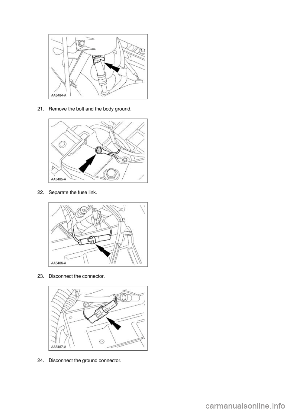
21. Remove the bolt and the body ground.
22. Separate the fuse link.
23. Disconnect the connector.
24. Disconnect the ground connector. �K�l�j . 5 �b�a
122003 Mustang Workshop Manual
17. 11. 2011file:///C:/Ford/2000 - 2004/tsocache/SHEF_4464/S3B~us~en~ ...
Page 1373 of 4378
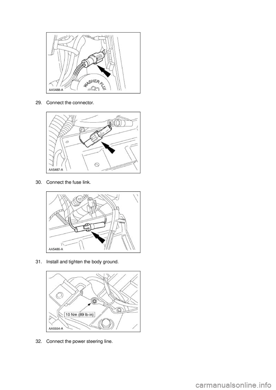
29. Connect the connector.
30. Connect the fuse link.
31. Install and tighten the body ground.
32. Connect the power steering line. �K�l�j . 8 �b�a
132003 Mustang Workshop Manual
17. 11. 2011file:///C:/Ford/2000 - 2004/tsocache/SHEF_4464/S3B~us~en~ ...
Page 2037 of 4378

DIAGNOSIS AND TESTING
Starting System
Refer to Wiring Diagrams Cell
20 , Starting System for schematic and connector information.
Inspection and Verification WARNING: When servicing starter motor or carrying out other underhood work in the
vicinity of the starter motor, be aware that the heavy gauge battery input lead at the starter
solenoid is "electrically hot" at all times. A protective cap or boot is provided over this terminal
that must be installed after servicing. Be sure to disconnect the battery negative cable before
servicing the starter. Failure to follow these instructions may result in personal injury.
WARNING: When working in area of the starter motor, be careful to avoid touching hot
exhaust components. Failure to follow these instructions may result in personal injury.
WARNING: When using a remote starter switch or jumper wire, be sure the ignition switch
is in the OFF position and the transmission is in PARK (A/T) or Neutral (M/T) with the parking
brake control fully applied.
1. Verify the customers concern by operating the starting system to duplicate the conditions.
2. Inspect to determine if any of the following mechanical or electrical concerns apply.
3. If the inspection reveals an obvious concern that can be readily identified, repair as necessary.
4. If the concern remains after the inspection, determine the symptom. GO to Symptom Chart .
SECTION 303-
06: Starting System 2003 Mustang Workshop Manual Special Tool(s)
Digital Multimeter
105-
R0051 or equivalent Visual Inspection Chart
Mechanical Electrical
�z
Starter motor
�z Brackets �z
Battery
�z Battery junction box (BJB) fuse ignition switch (40A)
�z Central junction box (CJB) Fuse 6 (20A)
�z Fuse 24 (10A)
�z Damaged wiring harness
�z Starter Relay
�z Loose or corroded connections �K�l�j . 1 �b�a
112003 Mustang Workshop Manual
18. 11. 2011file:///C:/Ford/2000 - 2004/tsocache/SHEF_4464/S3B~us~en~ ...
Page 2038 of 4378

Symptom Chart
Pinpoint Tests
PINPOINT TEST A: THE ENGINE DOES NOT CRANK AND THE
RELAY DOES CLICK
SYMPTOM CHART Condition
Possible Sources Action
�z The engine does
not crank and the
relay does click �z
Battery.
�z Fuse.
�z Starter
motor/solenoid.
�z Ignition switch.
�z Circuit. �z
Go To Pinpoint Test A .
�z The engine does
not crank and the
relay does not
click �z
Fuse.
�z Battery.
�z Starter relay.
�z Ignition switch.
�z Digital transmission
range (TR) sensor.
�z Starter solenoid.
�z Clutch pedal
position (CPP)
switch.
�z Circuit. �z
Go To Pinpoint Test B .
�z The engine
cranks slowly �z
Battery.
�z Starter
motor/solenoid.
�z Circuit. �z
Go To Pinpoint Test C .
�z Unusual starter
noise �z
Starter motor
mounting.
�z Starter motor.
�z Incorrect starter
drive engagement. �z
Go To Pinpoint Test D .
�z The starter spins
but the engine
does not crank �z
Starter Motor �zINSPECT the starter motor
mounting and engagement.
REPAIR as necessary.
�z Damaged
flywheel/ring gear
teeth. �z
INSPECT the flywheel/ring
gear for damaged, missing or
worn teeth. REPAIR as
necessary. Test Step Result / Action to Take
A1 CHECK THE VOLTAGE TO THE STARTER RELAY
�z
Measure the voltage between the starter relay pin 30,
circuit 1050 (LG/VT) and ground. Yes
GO to
A2 .
No
REPAIR circuit 1050 (LG/VT) �K�l�j . 2 �b�a
112003 Mustang Workshop Manual
18. 11. 2011file:///C:/Ford/2000 - 2004/tsocache/SHEF_4464/S3B~us~en~ ...