Page 2677 of 4378
6. Disconnect the brake pedal-
to-power brake booster push rod.
1. Remove the self- locking pin.
2. Remove the BPP switch from the brake master cylinder push rod.
3. Remove the brake master cylinder push rod spacers (2B129).
4. Remove the brake master cylinder push rod bushing (2474).
7. Disconnect the clutch pedal position (CPP) switch electrical connector.
8. Disconnect the deactivation switch connector from the wiring harness. �K�l�j . 2 �b�a
62003 Mustang Workshop Manual
18. 11. 2011file:///C:/Ford/2000 - 2004/tsocache/SHEF_2308/S3B~us~en~ ...
Page 2704 of 4378
13. Disconnect the reversing lamp switch electrical connector. Disconnect the wiring harness from
the transmission.
14. Remove the starter motor (11001). For additional information, refer to Section 303 - 06 .
15. Disconnect the output shaft speed sensor (OSS) electrical connector. Disconnect the wiring harness from the transmission.
16. Remove the bolt and the clutch release lever cover. �K�l�j . 3 �b�a
62003 Mustang Workshop Manual
18. 11. 2011file:///C:/Ford/2000 - 2004/tsocache/SHEF_2308/S3B~us~en~ ...
Page 2777 of 4378
Remove the driveshaft. For additional information, refer to
Section 205 - 01 .
8. Disconnect the reversing lamp switch electrical connector. Disconnect the wiring harness from the transmission.
9. Remove the starter motor. For additional information, refer to Section 303 - 06 .
10. Remove the bolts.
11. Remove the starter solenoid nuts and position the wires aside. �K�l�j . 2 �b�a
52003 Mustang Workshop Manual
18. 11. 2011file:///C:/Ford/2000 - 2004/tsocache/SHEF_2308/S3B~us~en~ ...
Page 2778 of 4378
12. Remove the starter motor.
13. Disconnect the OSS sensor electrical connector. Disconnect the wiring harness from the
transmission.
14. Remove the bolt and the clutch release lever cover.
15. CAUTION: To prevent component damage, do not depress the clutch pedal with the
transmission removed.
Disengage the clutch release cable from the clutch release fork.
16. Remove the clutch cable retainer and remove the clutch cable from the transmission. �K�l�j . 3 �b�a
52003 Mustang Workshop Manual
18. 11. 2011file:///C:/Ford/2000 - 2004/tsocache/SHEF_2308/S3B~us~en~ ...
Page 2854 of 4378
14. Disengage the clutch release cable from the clutch release fork.
15. Disconnect the wiring harness from the transmission.
16. Disconnect the output shaft speed (OSS) sensor electrical connector.
17. Disconnect the reverse lamp electrical connector. �K�l�j . 4 �b�a
52003 Mustang Workshop Manual
18. 11. 2011file:///C:/Ford/2000 - 2004/tsocache/SHEF_2308/S3B~us~en~ ...
Page 2927 of 4378
4. Connect the wiring harness to the transmission.
5. Connect the clutch release cable to the clutch release fork.
6. Install the clutch release lever cover and bolt.
7. Install the transmission crossmember and the bolts. �K�l�j . 2 �b�a
52003 Mustang Workshop Manual
18. 11. 2011file:///C:/Ford/2000 - 2004/tsocache/SHEF_2308/S3B~us~en~ ...
Page 2932 of 4378

DESCRIPTION AND OPERATION
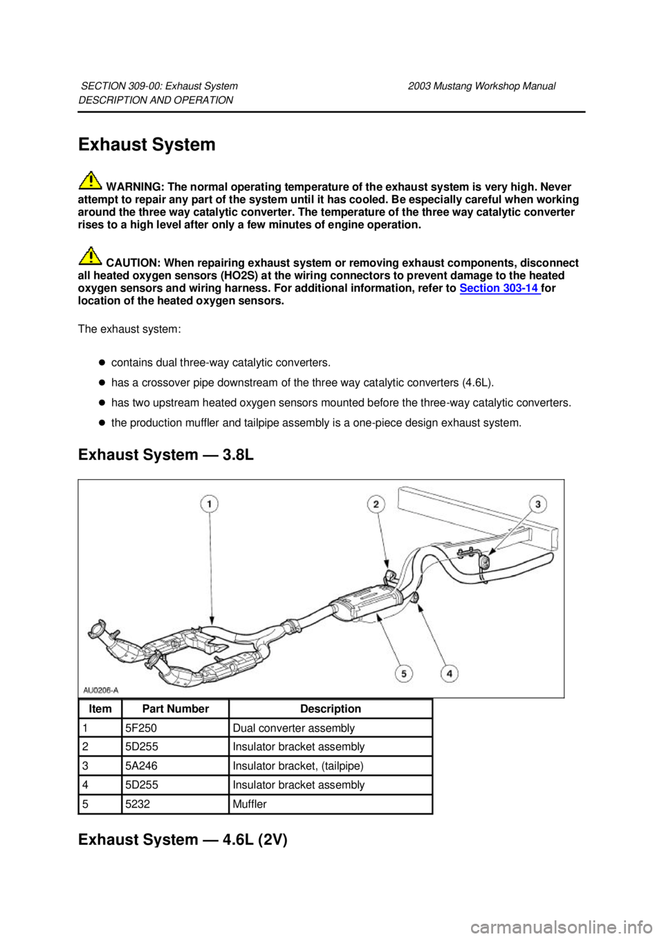
Exhaust System
WARNING: The normal operating temperature of the exhaust system is very high. Never
attempt to repair any part of the system until it has cooled. Be especially careful when working
around the three way catalytic converter. The temperature of the three way catalytic converter
rises to a high level after only a few minutes of engine operation.
CAUTION: When repairing exhaust system or removing exhaust components, disconnect
all heated oxygen sensors (HO2S) at the wiring connectors to prevent damage to the heated
oxygen sensors and wiring harness. For additional information, refer to Section 303 - 14 for
location of the heated oxygen sensors.
The exhaust system:
�zcontains dual three- way catalytic converters.
�z has a crossover pipe downstream of the three way catalytic converters (4.6L).
�z has two upstream heated oxygen sensors mounted before the three- way catalytic converters.
�z the production muffler and tailpipe assembly is a one- piece design exhaust system.
Exhaust System — 3.8L Exhaust System — 4.6L (2V) SECTION 309-
00: Exhaust System 2003 Mustang Workshop Manual Item Part Number Description
1 5F250 Dual converter assembly
2 5D255 Insulator bracket assembly
3 5A246 Insulator bracket, (tailpipe)
4 5D255 Insulator bracket assembly
5 5232 Muffler �K�l�j . 1 �b�a
32003 Mustang Workshop Manual
18. 11. 2011file:///C:/Ford/2000 - 2004/tsocache/SHEF_2308/S3B~us~en~ ...
Page 2946 of 4378
REMOVAL AND INSTALLATION
Dual Converter Y-
Pipe —3.8L
Removal
NOTE: The RH and LH catalytic converters are serviceable separately.
1. Raise and support the vehicle. For additional information, refer to Section 100 - 02 .
2. CAUTION: When repairing the exhaust system or removing exhaust components,
disconnect all heated oxygen sensors (HO2S) (9F472) and catalyst monitor sensors at
the wiring connectors to prevent damage to the sensors and wiring harnesses.
Disconnect the RH and LH HO2S connectors.
3. Disconnect the RH and LH catalyst monitor sensor connectors.
4. Remove the dual converter assembly nuts.
SECTION 309-
00: Exhaust System 2003 Mustang Workshop Manual �K�l�j . 1 �b�a
52003 Mustang Workshop Manual
18. 11. 2011file:///C:/Ford/2000 - 2004/tsocache/SHEF_2308/S3B~us~en~ ...