Page 1382 of 4378

b
P=Primary, S=Secondary, E=Exhaust
c Time necessary for plunger to leak down 1.6 mm of travel with 222 N force and leak down fluid in
tappet.
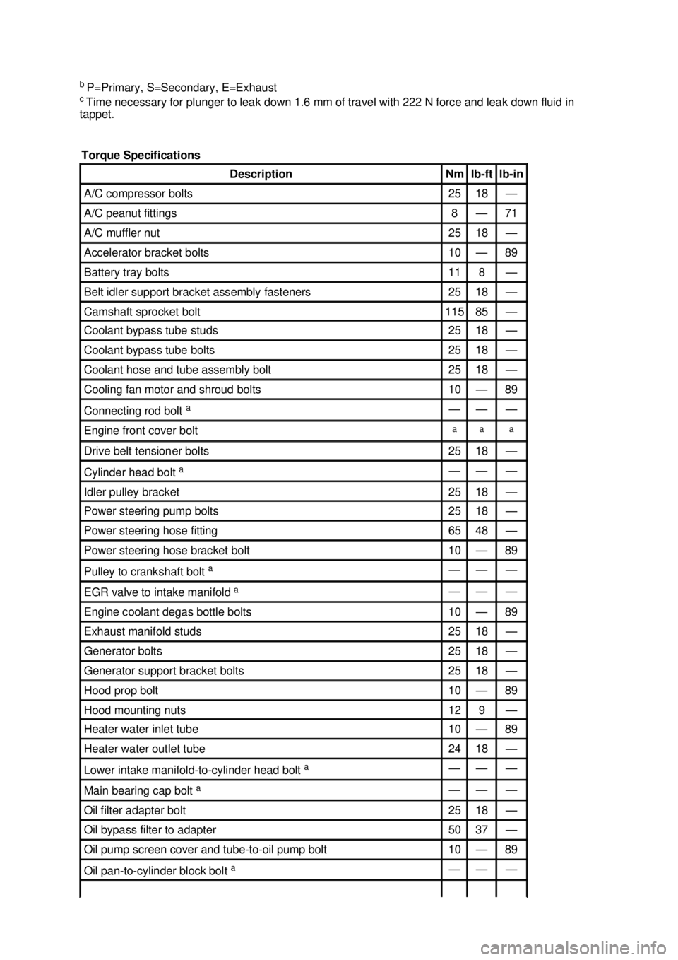
Torque Specifications Description Nm lb-
ft lb-
in A/C compressor bolts 25 18 —
A/C peanut fittings 8 — 71
A/C muffler nut 25 18 —
Accelerator bracket bolts 10 — 89
Battery tray bolts 11 8 —
Belt idler support bracket assembly fasteners 25 18 —
Camshaft sprocket bolt 115 85 —
Coolant bypass tube studs 25 18 —
Coolant bypass tube bolts 25 18 —
Coolant hose and tube assembly bolt 25 18 —
Cooling fan motor and shroud bolts 10 — 89
Connecting rod bolt
a — — —
Engine front cover bolt a a a
Drive belt tensioner bolts 25 18 —
Cylinder head bolt
a — — —
Idler pulley bracket 25 18 —
Power steering pump bolts 25 18 —
Power steering hose fitting 65 48 —
Power steering hose bracket bolt 10 — 89
Pulley to crankshaft bolt
a — — —
EGR valve to intake manifold
a — — —
Engine coolant degas bottle bolts 10 — 89
Exhaust manifold studs 25 18 —
Generator bolts 25 18 —
Generator support bracket bolts 25 18 —
Hood prop bolt 10 — 89
Hood mounting nuts 12 9 —
Heater water inlet tube 10 — 89
Heater water outlet tube 24 18 —
Lower intake manifold-
to-cylinder head bolt a — — —
Main bearing cap bolt
a — — —
Oil filter adapter bolt 25 18 —
Oil bypass filter to adapter 50 37 —
Oil pump screen cover and tube-
to-oil pump bolt 10 — 89
Oil pan-to-
cylinder block bolt a — — — �K�l�j . 4 �b�a
62003 Mustang Workshop Manual
17. 11. 2011file:///C:/Ford/2000 - 2004/tsocache/SHEF_4464/S3B~us~en~ ...
Page 1557 of 4378
NOTE:
Lubricate the piston rings, cylinder walls and connecting rod bearings with clean engine
oil.
Using the special tool push the pistons through the top of the cylinder block.
14. CAUTION: Do not scratch the cylinder walls or the crankshaft journals with the
connecting rod.
NOTE: Make sure the crankshaft is at top dead center (TDC).
Using the special tool, install the connecting rod assemblies.
15. NOTE: The rod bearing cap bolts are torque- to-yield. Install new bolts, each time they are
serviced.
Install the connecting rod bearing caps and bolts. and tighten in three stages.
�zStage 1: Tighten to 25 Nm (18 lb- ft).
�z Stage 2: Tighten to 45 Nm (33 lb- ft).
�z Stage 3: Tighten an additional 90 degrees. �K�l�j . 8 �b�a
352003 Mustang Workshop Manual
17. 11. 2011file:///C:/Ford/2000 - 2004/tsocache/SHEF_4464/S3B~us~en~ ...
Page 1606 of 4378

i
Measured at 42 mm from piston dome, at 90 degrees to the piston pin.
j Piston pin outer diameter is larger than piston pin bore, providing a possible interference fit.
k Specification in 90.200 mm diameter gauge.
l With installation of a new filter.
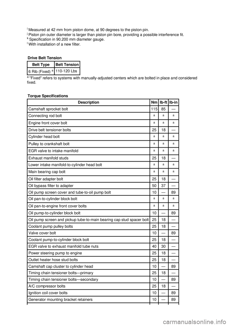
a "Fixed" refers to systems with manually- adjusted centers which are bolted in place and considered
fixed. Drive Belt Tension Belt Type Belt Tension
6 Rib (Fixed)
a 110-
120 Lbs
Torque Specifications Description Nm lb-
ft lb-
in Camshaft sprocket bolt 115 85 —
Connecting rod bolt a a a
Engine front cover bolt a a a
Drive belt tensioner bolts 25 18 —
Cylinder head bolt a a a
Pulley to crankshaft bolt a a a
EGR valve to intake manifold a a a
Exhaust manifold studs 25 18 —
Lower intake manifold-
to-cylinder head bolt a a a
Main bearing cap bolt a a a
Oil filter adapter bolt 25 18 —
Oil bypass filter to adapter 50 37 —
Oil pump screen cover and tube-
to-oil pump bolt 10 — 89
Oil pan-to-
cylinder block bolt a a a
Oil pan-to-
engine front cover bolts a a a
Oil pump-
to-cylinder block bolt 10 — 89
Oil pump screen and pickup tube-
to-main bearing cap stud spacer bolt 25 18 —
Coolant pump pulley bolts 25 18 —
Valve cover bolt 10 — 89
Coolant pump-
to-cylinder block bolt 25 18 —
EGR valve to exhaust manifold tube nuts 40 30 —
Power steering pump to engine 25 18 —
Outlet heater hose stud bolts 25 18 —
Camshaft cap cluster to cylinder head 10 — 89
Timing chain tensioner bolts—
primary 25 18 —
Timing chain tensioner bolts—
secondary 10 — 89
A/C compressor bolts 25 18 —
Ignition coil cover bolts 10 — 89
Generator mounting bracket retainers 10 — 89 �K�l�j . 5 �b�a
62003 Mustang Workshop Manual
17. 11. 2011file:///C:/Ford/2000 - 2004/tsocache/SHEF_4464/S3B~us~en~ ...
Page 1607 of 4378
a
Refer to the procedure. Flexplate bolts 80 59 —
Flywheel bolts 85 63 —
Torque converter nuts 36 27 —
Oil level indicator tube retainer 10 — 89
Primary timing chain guide-
to-engine bolts 10 — 89
Oil pump screen and pickup tube spacer to main bearing stud 25 18 —
Accelerator cable bracket 10 — 89
Belt idler pulley bolt 25 18 —
Sub-
frame brace nuts 41 30 —
Air intake scoop bolts 25 18 —
Air intake scoop bracket bolt 25 18 —
Air intake scoop bracket nuts 25 18 —
Air intake scoop bracket throttle body nut 9 — 80
Exhaust gas recirculation (EGR) vacuum regulator solenoid bolts 10 — 89 �K�l�j . 6 �b�a
62003 Mustang Workshop Manual
17. 11. 2011file:///C:/Ford/2000 - 2004/tsocache/SHEF_4464/S3B~us~en~ ...
Page 1747 of 4378
43. Remove the three bolts and the starter.
Automatic transmission vehicles 44. Remove the flywheel inspection cover.
45. Remove the torque converter nuts. All vehicles �K�l�j . 11 �b�a
192003 Mustang Workshop Manual
17. 11. 2011file:///C:/Ford/2000 - 2004/tsocache/SHEF_4464/S3B~us~en~ ...
Page 1797 of 4378
13.
CAUTION: Do not scratch the cylinder walls or crankshaft journals with the
connecting rod.
NOTE: Make sure that the piston arrow is facing forward.
NOTE: Lubricate the piston rings, cylinder walls and connecting rod bearings with clean engine
oil.
Using the special tool push the pistons through the top of the cylinder block.
14. CAUTION: Do not scratch the cylinder walls or the crankshaft journals with the
connecting rod.
NOTE: Make sure the crankshaft is at T.D.C.
Using the special tool, install the connecting rod assemblies.
15. NOTE: The rod bearing cap bolts are torque- to-yield. Install new bolts each time they are
serviced.
Install the connecting rod bearing caps and bolts and tighten in three stages.
�zStage 1: tighten to 25 Nm (18 lb- ft).
�z Stage 2: tighten to 45 Nm (33 lb- ft).
�z Stage 3: tighten an additional 90 degrees. �K�l�j . 7 �b�a
302003 Mustang Workshop Manual
17. 11. 2011file:///C:/Ford/2000 - 2004/tsocache/SHEF_4464/S3B~us~en~ ...
Page 1830 of 4378
32. Install the torque converter nuts.
33. Install the flywheel inspection cover.
34. Install the driveshaft onto the transmission output shaft, aligning the index-
mark in the six
o'clock position.
35. CAUTION: Use new bolts to install the driveshaft. If new bolts are not available,
apply threadlock to the threads of the original bolts.
CAUTION: The driveshaft centering socket yoke fits tightly on the rear axle pinion
flange pilot. To make sure the yoke seats squarely on the flange, tighten the bolts evenly
in the sequence shown.
NOTE: Align the marks made on the flange and driveshaft during removal.
Position the driveshaft and install the driveshaft- to-pinion flange bolts in the sequence shown. �K�l�j . 10 �b�a
182003 Mustang Workshop Manual
17. 11. 2011file:///C:/Ford/2000 - 2004/tsocache/SHEF_4464/S3B~us~en~ ...
Page 1839 of 4378

SPECIFICATIONS
SECTION 303-
03A: Engine Cooling 2003 Mustang Workshop Manual General Specifications
Item Specification
Cooling System Capacity 15.2 L (4.0 gal)
Coolant Type
Motorcraft Premium Gold Engine Coolant VC-7-
A in
(Oregon VC -7-B) (yellow color) WSS-
M97B51- A1 Other Chemicals
Motorcraft Premium Cooling System Flush VC-
1 ESR-
M14P7-A Premium Long Life Grease XG-1-
C ESA-
M1C75- B Cooling System Stop Leak Pellets
VC-
6 ESE-
M99B37- B5 except as noted in ES-
F65E-19A511- AA Gasket Adhesive TA-
6 WSS-
M2G408- A Cooling System Pressure Test Specifications 138 kPa (20 psi)
Radiator Cap Pressure Test Specifications 110 kPa (16 psi)
Thermostat Opening Temperatures
Starts to open (4.6L 2V) 87-
93°C (192- 199°F) Starts to open (3.8L) 86.7-
90.6°C (189- 196°F) Starts to open (Cobra) 80-
83°C (175- 182°F) Fully open 104°C (219°F)
Torque Specifications Description Nm lb-
ft lb-
in Accelerator cable bracket bolts 10 — 89
Cylinder block drain plug 20 15 —
Exhaust manifold to EGR valve tube nut 35 26 —
Fan shroud bolts 10 — 89
Fan motor bolts 10 — 89
Degas bottle nuts 10 — 89
Coolant expansion tank bracket bolts 10 — 89
Radiator support bracket bolts 30 22 —
Transmission fluid cooler fittings 30 22 —
Coolant outlet connection bolts (3.8L) 10 — 89
Bypass tube bracket bolts (3.8L) 10 — 89
Bypass tube bolts (4.6L) 10 — 89
Bypass tube nuts (Supercharged engine) 25 18 —
Coolant hose mounting bolt 25 18 — �K�l�j . 1 �b�a
22003 Mustang Workshop Manual
17. 11. 2011file:///C:/Ford/2000 - 2004/tsocache/SHEF_4464/S3B~us~en~ ...