Page 4117 of 4378

2.
WARNING: Incorrect centralization may result in premature component failure. If in
doubt when centralizing the clockspring, repeat the centralizing procedure. Failure to
follow this instruction may result in personal injury.
CAUTION: Make sure the road wheels are in the straight ahead position.
NOTE: If a clockspring has rotated out of center, follow through with this step.
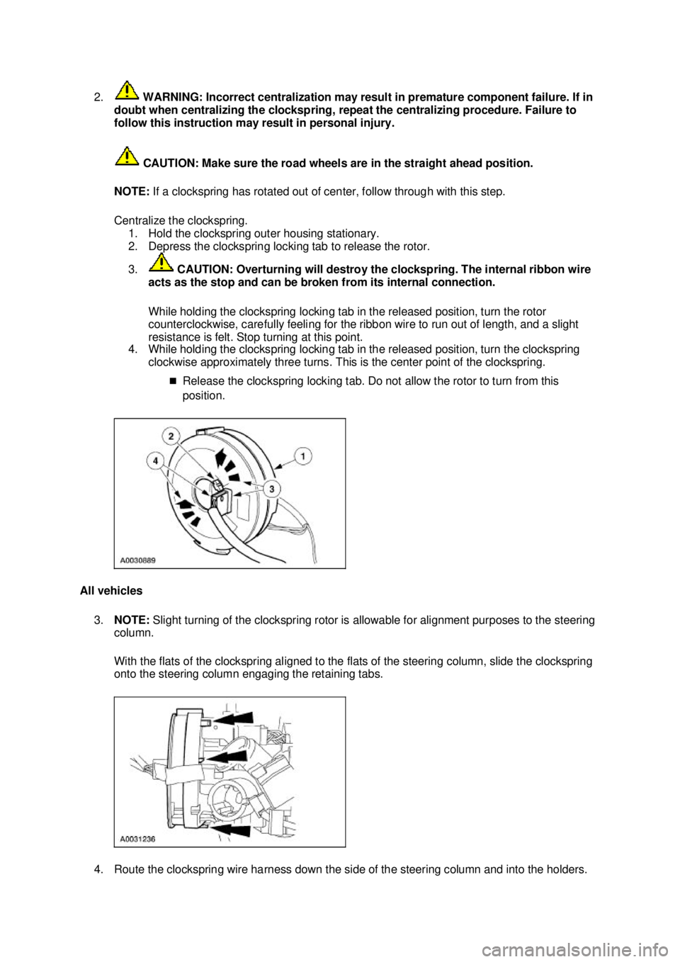
Centralize the clockspring. 1. Hold the clockspring outer housing stationary.
2. Depress the clockspring locking tab to release the rotor.
3. CAUTION: Overturning will destroy the clockspring. The internal ribbon wire
acts as the stop and can be broken from its internal connection.
While holding the clockspring locking tab in the released position, turn the rotor
counterclockwise, carefully feeling for the ribbon wire to run out of length, and a slight
resistance is felt. Stop turning at this point.
4. While holding the clockspring locking tab in the released position, turn the clockspring
clockwise approximately three turns. This is the center point of the clockspring.
�„Release the clockspring locking tab. Do not allow the rotor to turn from this
position.
All vehicles 3. NOTE: Slight turning of the clockspring rotor is allowable for alignment purposes to the steering
column.
With the flats of the clockspring aligned to the flats of the steering column, slide the clockspring
onto the steering column engaging the retaining tabs.
4. Route the clockspring wire harness down the side of the steering column and into the holders. �K�l�j . 6 �b�a
112003 Mustang Workshop Manual
18. 11. 2011file:///C:/Ford/2000 - 2004/tsocache/SHEF_5108/S3B~us~en~ ...
Page 4118 of 4378
5. Remove the restraint system diagnostic tool from the vehicle harness side of the clockspring
electrical connector.
6. Connect the two clockspring electrical connectors. Position the clockspring electrical connectors onto the bracket.
7. Install the key- in-ignition warning indicator switch.
8. Install the passive anti- theft system (PATS) transmitter.
1. Position the PATS transmitter to the steering column.
2. Install the screw. �K�l�j . 7 �b�a
112003 Mustang Workshop Manual
18. 11. 2011file:///C:/Ford/2000 - 2004/tsocache/SHEF_5108/S3B~us~en~ ...
Page 4119 of 4378
9. Reposition the upper steering column shroud.
10. Install the ignition switch lock cylinder.
Vehicle repairs reusing the same clockspring 11. Remove the tape applied during clockspring removal.
All vehicles 12. Install the lower steering column shroud. 1. Position the lower steering column shroud.
2. Install the screws. �K�l�j . 8 �b�a
112003 Mustang Workshop Manual
18. 11. 2011file:///C:/Ford/2000 - 2004/tsocache/SHEF_5108/S3B~us~en~ ...
Page 4120 of 4378

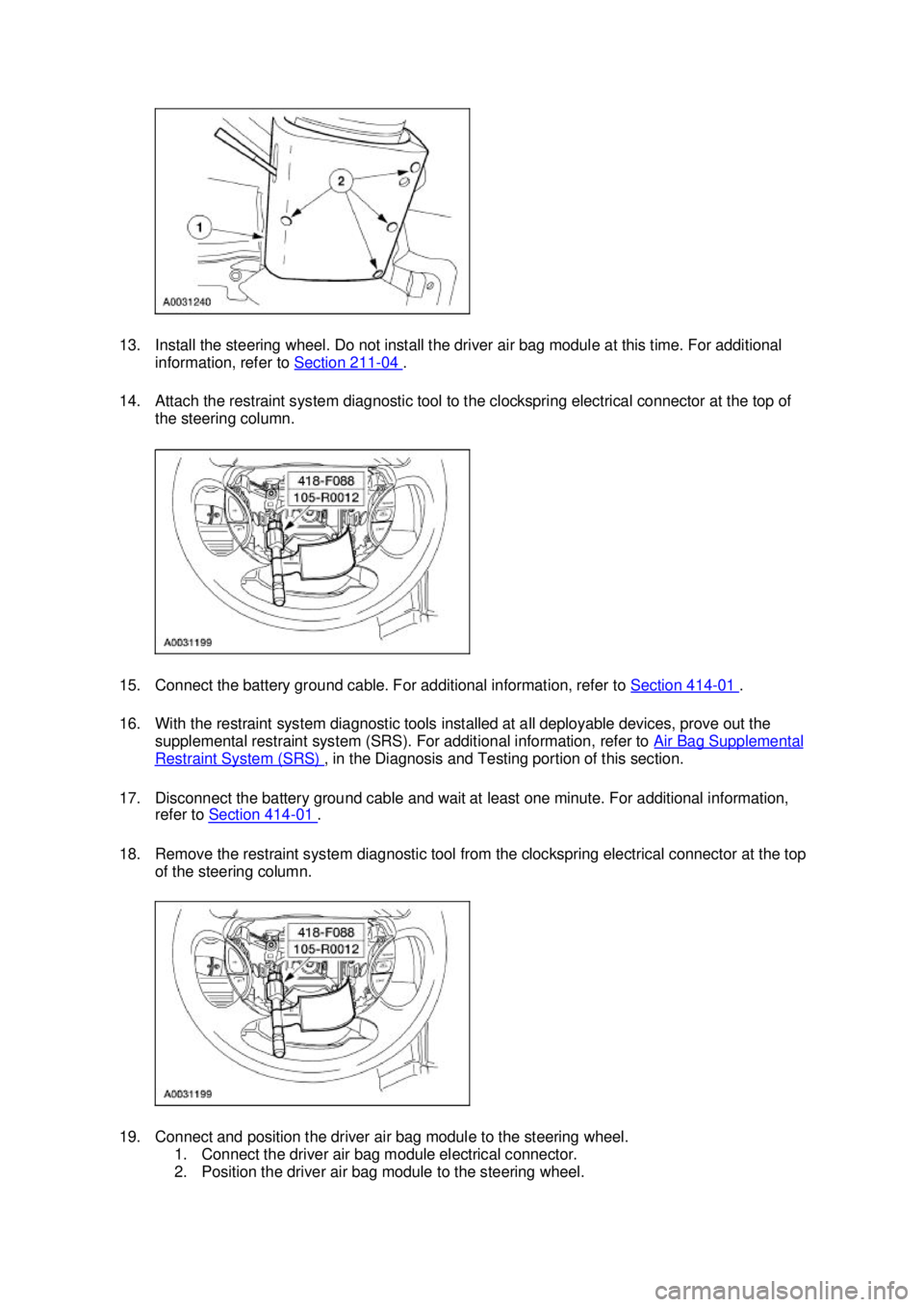
13. Install the steering wheel. Do not install the driver air bag module at this time. For additional
information, refer to Section 211 - 04 .
14. Attach the restraint system diagnostic tool to the clockspring electrical connector at the top of the steering column.
15. Connect the battery ground cable. For additional information, refer to Section 414 - 01 .
16. With the restraint system diagnostic tools installed at all deployable devices, prove out the supplemental restraint system (SRS). For additional information, refer to Air Bag Supplemental Restraint System (SRS) , in the Diagnosis and Testing portion of this section.
17. Disconnect the battery ground cable and wait at least one minute. For additional information, refer to Section 414 - 01 .
18. Remove the restraint system diagnostic tool from the clockspring electrical connector at the top of the steering column.
19. Connect and position the driver air bag module to the steering wheel. 1. Connect the driver air bag module electrical connector.
2. Position the driver air bag module to the steering wheel. �K�l�j . 9 �b�a
112003 Mustang Workshop Manual
18. 11. 2011file:///C:/Ford/2000 - 2004/tsocache/SHEF_5108/S3B~us~en~ ...
Page 4151 of 4378

Camshaft Position (CMP) SensorEngine Performance
Central Control ModuleAnti-Theft System
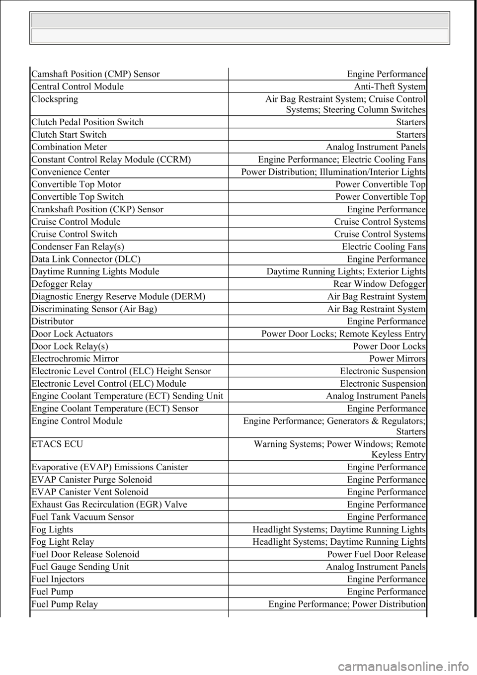
ClockspringAir Bag Restraint System; Cruise Control
Systems; Steering Column Switches
Clutch Pedal Position SwitchStarters
Clutch Start SwitchStarters
Combination MeterAnalog Instrument Panels
Constant Control Relay Module (CCRM)Engine Performance; Electric Cooling Fans
Convenience CenterPower Distribution; Illu mination/Interior Lights
Convertible Top MotorPower Convertible Top
Convertible Top SwitchPower Convertible Top
Crankshaft Position (CKP) SensorEngine Performance
Cruise Control ModuleCruise Control Systems
Cruise Control SwitchCruise Control Systems
Condenser Fan Relay(s)Electric Cooling Fans
Data Link Connector (DLC)Engine Performance
Daytime Running Lights ModuleDaytime Running Lights; Exterior Lights
Defogger RelayRear Window Defogger
Diagnostic Energy Reserve Module (DERM)Air Bag Restraint System
Discriminating Sensor (Air Bag)Air Bag Restraint System
DistributorEngine Performance
Door Lock ActuatorsPower Door Locks; Remote Keyless Entry
Door Lock Relay(s)Power Door Locks
Electrochromic MirrorPower Mirrors
Electronic Level Control (ELC) Height SensorElectronic Suspension
Electronic Level Control (ELC) ModuleElectronic Suspension
Engine Coolant Temper ature (ECT) Sending UnitAnalog Instrument Panels
Engine Coolant Temperature (ECT) SensorEngine Performance
Engine Control ModuleEngine Performance; Ge nerators & Regulators;
Starters
ETACS ECUWarning Systems; Power Windows; Remote Keyless Entry
Evaporative (EVAP) Emissions CanisterEngine Performance
EVAP Canister Purge SolenoidEngine Performance
EVAP Canister Vent SolenoidEngine Performance
Exhaust Gas Recirculation (EGR) ValveEngine Performance
Fuel Tank Vacuum SensorEngine Performance
Fog LightsHeadlight Systems; Daytime Running Lights
Fog Light RelayHeadlight Systems; Daytime Running Lights
Fuel Door Release SolenoidPower Fuel Door Release
Fuel Gauge Sending UnitAnalog Instrument Panels
Fuel InjectorsEngine Performance
Fuel PumpEngine Performance
Fuel Pump RelayEngine Performance; Power Distribution
111
15 ноября 2011 г. 20:18:43Page 6 © 2006 Mitchell Repair Information Company, LLC.
Page 4154 of 4378

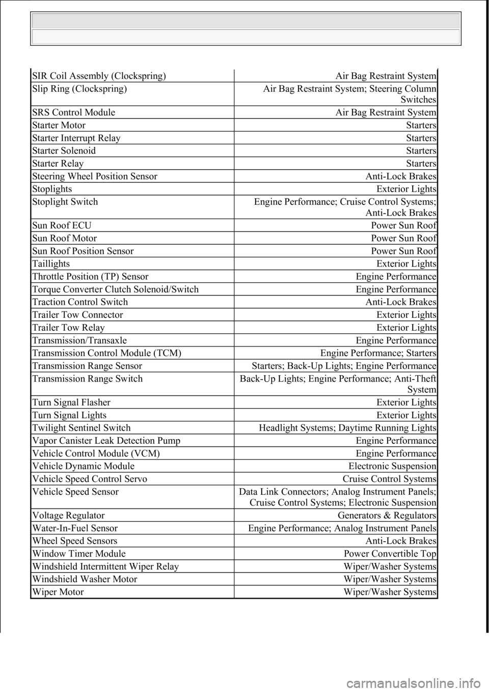
SIR Coil Assembly (Clockspring)Air Bag Restraint System
Slip Ring (Clockspring)Air Bag Restraint System; Steering Column Switches
SRS Control ModuleAir Bag Restraint System
Starter MotorStarters
Starter Interrupt RelayStarters
Starter SolenoidStarters
Starter RelayStarters
Steering Wheel Position SensorAnti-Lock Brakes
StoplightsExterior Lights
Stoplight SwitchEngine Performance; Cruise Control Systems;
Anti-Lock Brakes
Sun Roof ECUPower Sun Roof
Sun Roof MotorPower Sun Roof
Sun Roof Position SensorPower Sun Roof
TaillightsExterior Lights
Throttle Position (TP) SensorEngine Performance
Torque Converter Clutch Solenoid/SwitchEngine Performance
Traction Control SwitchAnti-Lock Brakes
Trailer Tow ConnectorExterior Lights
Trailer Tow RelayExterior Lights
Transmission/TransaxleEngine Performance
Transmission Control Module (TCM)Engine Performance; Starters
Transmission Range SensorStarters; Back-Up Lights; Engine Performance
Transmission Range SwitchBack-Up Lights; Engine Performance; Anti-Theft
System
Turn Signal FlasherExterior Lights
Turn Signal LightsExterior Lights
Twilight Sentinel SwitchHeadlight Systems; Daytime Running Lights
Vapor Canister Le ak Detection PumpEngine Performance
Vehicle Control Module (VCM)Engine Performance
Vehicle Dynamic ModuleElectronic Suspension
Vehicle Speed Control ServoCruise Control Systems
Vehicle Speed SensorData Link Connectors; Analog Instrument Panels;
Cruise Control Systems; Electronic Suspension
Voltage RegulatorGenerators & Regulators
Water-In-Fuel SensorEngine Performance; Analog Instrument Panels
Wheel Speed SensorsAnti-Lock Brakes
Window Timer ModulePower Convertible Top
Windshield Intermittent Wiper RelayWiper/Washer Systems
Windshield Washer MotorWiper/Washer Systems
Wiper MotorWiper/Washer Systems
111
15 ноября 2011 г. 20:18:43Page 9 © 2006 Mitchell Repair Information Company, LLC.