2003 FORD F350 air condition
[x] Cancel search: air conditionPage 1 of 280

Introduction 4
Instrument Cluster 12
Warning and control lights 12
Gauges 16
Entertainment Systems 20
AM/FM stereo 20
AM/FM stereo cassette 22
AM/FM stereo cassette with CD 25
AM/FM stereo with CD 29
CD changer 32
Climate Controls 36
Heater only 36
Manual heating and air conditioning 37
Lights 39
Headlamps 39
Turn signal control 41
Bulb replacement 42
Driver Controls 49
Windshield wiper/washer control 49
Steering wheel adjustment 50
Power windows 53
Mirrors 54
Speed control 57
Message center 60
Table of Contents
1
ProCarManuals.com
Page 12 of 280
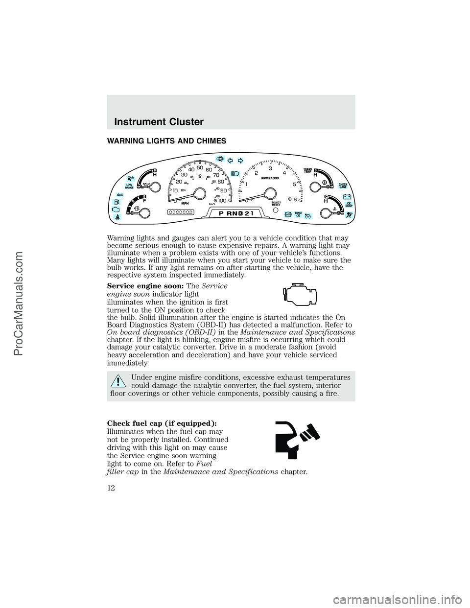
WARNING LIGHTS AND CHIMES
Warning lights and gauges can alert you to a vehicle condition that may
become serious enough to cause expensive repairs. A warning light may
illuminate when a problem exists with one of your vehicle’s functions.
Many lights will illuminate when you start your vehicle to make sure the
bulb works. If any light remains on after starting the vehicle, have the
respective system inspected immediately.
Service engine soon:TheService
engine soonindicator light
illuminates when the ignition is first
turned to the ON position to check
the bulb. Solid illumination after the engine is started indicates the On
Board Diagnostics System (OBD-II) has detected a malfunction. Refer to
On board diagnostics (OBD-II)in theMaintenance and Specifications
chapter. If the light is blinking, engine misfire is occurring which could
damage your catalytic converter. Drive in a moderate fashion (avoid
heavy acceleration and deceleration) and have your vehicle serviced
immediately.
Under engine misfire conditions, excessive exhaust temperatures
could damage the catalytic converter, the fuel system, interior
floor coverings or other vehicle components, possibly causing a fire.
Check fuel cap (if equipped):
Illuminates when the fuel cap may
not be properly installed. Continued
driving with this light on may cause
the Service engine soon warning
light to come on. Refer toFuel
filler capin theMaintenance and Specificationschapter.
Instrument Cluster
12
ProCarManuals.com
Page 13 of 280
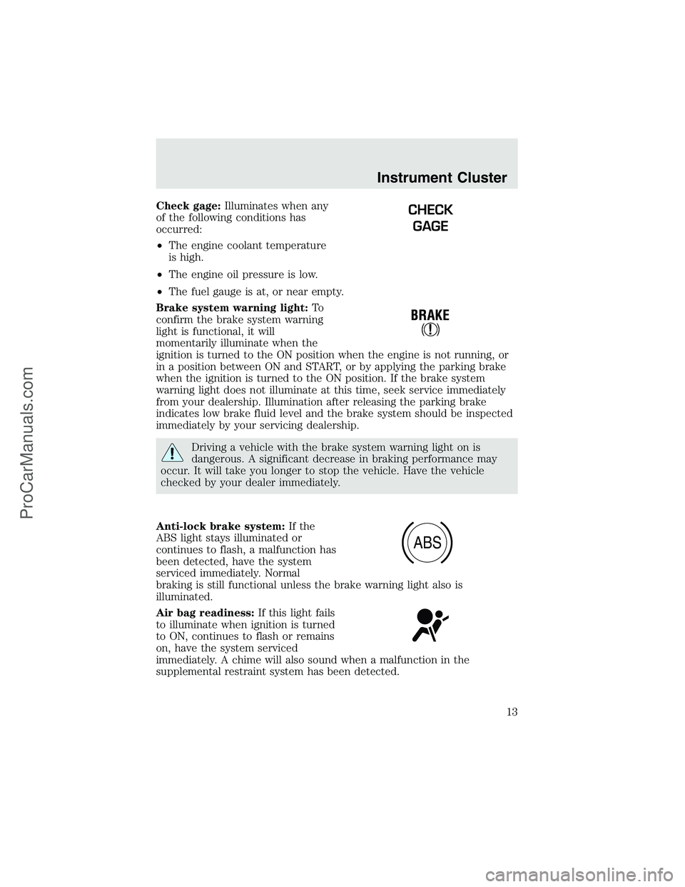
Check gage:Illuminates when any
of the following conditions has
occurred:
•The engine coolant temperature
is high.
•The engine oil pressure is low.
•The fuel gauge is at, or near empty.
Brake system warning light:To
confirm the brake system warning
light is functional, it will
momentarily illuminate when the
ignition is turned to the ON position when the engine is not running, or
in a position between ON and START, or by applying the parking brake
when the ignition is turned to the ON position. If the brake system
warning light does not illuminate at this time, seek service immediately
from your dealership. Illumination after releasing the parking brake
indicates low brake fluid level and the brake system should be inspected
immediately by your servicing dealership.
Driving a vehicle with the brake system warning light on is
dangerous. A significant decrease in braking performance may
occur. It will take you longer to stop the vehicle. Have the vehicle
checked by your dealer immediately.
Anti-lock brake system:If the
ABS light stays illuminated or
continues to flash, a malfunction has
been detected, have the system
serviced immediately. Normal
braking is still functional unless the brake warning light also is
illuminated.
Air bag readiness:If this light fails
to illuminate when ignition is turned
to ON, continues to flash or remains
on, have the system serviced
immediately. A chime will also sound when a malfunction in the
supplemental restraint system has been detected.
CHECK
GAGE
ABS
Instrument Cluster
13
ProCarManuals.com
Page 36 of 280
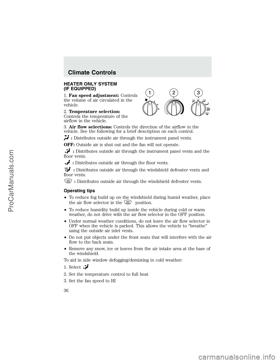
HEATER ONLY SYSTEM
(IF EQUIPPED)
1.Fan speed adjustment:Controls
the volume of air circulated in the
vehicle.
2.Temperature selection:
Controls the temperature of the
airflow in the vehicle.
3.Air flow selections:Controls the direction of the airflow in the
vehicle. See the following for a brief description on each control.
:Distributes outside air through the instrument panel vents.
OFF:Outside air is shut out and the fan will not operate.
:Distributes outside air through the instrument panel vents and the
floor vents.
:Distributes outside air through the floor vents.
:Distributes outside air through the windshield defroster vents and
floor vents.
:Distributes outside air through the windshield defroster vents.
Operating tips
•To reduce fog build up on the windshield during humid weather, place
the air flow selector in the
position.
•To reduce humidity build up inside the vehicle during cold or warm
weather, do not drive with the air flow selector in the OFF position.
•Under normal weather conditions, do not leave the air flow selector in
OFF when the vehicle is parked. This allows the vehicle to“breathe”
using the outside air inlet vents.
•Do not put objects under the front seats that will interfere with the air
flow to the back seats.
•Remove any snow, ice or leaves from the air intake area at the base of
the windshield.
To aid in side window defogging/demisting in cold weather:
1. Select
2. Set the temperature control to full heat
3. Set the fan speed to HI
Climate Controls
36
ProCarManuals.com
Page 37 of 280
4. Direct the outer instrument panel vents towards the side windows
To increase airflow to the outer instrument panel vents, close the vents
located in the middle of the instrument panel.
Do not place objects on top of the instrument panel as these
objects may become projectiles in a collision or sudden stop.
MANUAL HEATING AND AIR
CONDITIONING SYSTEM
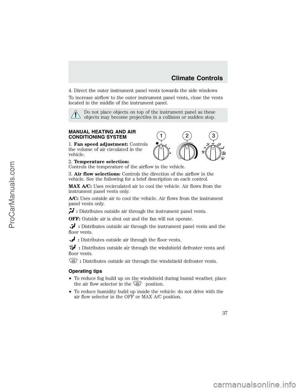
1.Fan speed adjustment:Controls
the volume of air circulated in the
vehicle.
2.Temperature selection:
Controls the temperature of the airflow in the vehicle.
3.Air flow selections:Controls the direction of the airflow in the
vehicle. See the following for a brief description on each control.
MAX A/C:Uses recirculated air to cool the vehicle. Air flows from the
instrument panel vents only.
A/C:Uses outside air to cool the vehicle. Air flows from the instrument
panel vents only.
:Distributes outside air through the instrument panel vents.
OFF:Outside air is shut out and the fan will not operate.
:Distributes outside air through the instrument panel vents and the
floor vents.
:Distributes outside air through the floor vents.
:Distributes outside air through the windshield defroster vents and
floor vents.
:Distributes outside air through the windshield defroster vents.
Operating tips
•To reduce fog build up on the windshield during humid weather, place
the air flow selector in the
position.
•To reduce humidity build up inside the vehicle: do not drive with the
air flow selector in the OFF or MAX A/C position.
Climate Controls
37
ProCarManuals.com
Page 38 of 280
•Under normal weather conditions, do not leave the air flow selector in
MAX A/C or OFF when the vehicle is parked. This allows the vehicle
to“breathe”using the outside air inlet vents.
•Do not put objects under the front seats that will interfere with the
airflow to the back seats.
•Remove any snow, ice or leaves from the air intake area at the base of
the windshield.
To aid in side window defogging/demisting in cold weather:
1. Select
2. Select A/C
3. Modulate the temperature control to maintain comfort.
4. Set the fan speed to HI
5. Direct the outer instrument panel vents towards the side windows
To increase airflow to the outer instrument panel vents, close the vents
located in the middle of the instrument panel.
Do not place objects on top of the instrument panel as these
objects may become projectiles in a collision or sudden stop.
Climate Controls
38
ProCarManuals.com
Page 60 of 280
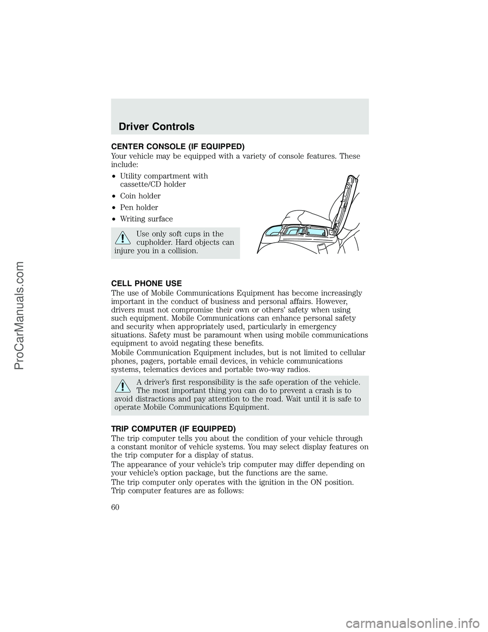
CENTER CONSOLE (IF EQUIPPED)
Your vehicle may be equipped with a variety of console features. These
include:
•Utility compartment with
cassette/CD holder
•Coin holder
•Pen holder
•Writing surface
Use only soft cups in the
cupholder. Hard objects can
injure you in a collision.
CELL PHONE USE
The use of Mobile Communications Equipment has become increasingly
important in the conduct of business and personal affairs. However,
drivers must not compromise their own or others’safety when using
such equipment. Mobile Communications can enhance personal safety
and security when appropriately used, particularly in emergency
situations. Safety must be paramount when using mobile communications
equipment to avoid negating these benefits.
Mobile Communication Equipment includes, but is not limited to cellular
phones, pagers, portable email devices, in vehicle communications
systems, telematics devices and portable two-way radios.
A driver’s first responsibility is the safe operation of the vehicle.
The most important thing you can do to prevent a crash is to
avoid distractions and pay attention to the road. Wait until it is safe to
operate Mobile Communications Equipment.
TRIP COMPUTER (IF EQUIPPED)
The trip computer tells you about the condition of your vehicle through
a constant monitor of vehicle systems. You may select display features on
the trip computer for a display of status.
The appearance of your vehicle’s trip computer may differ depending on
your vehicle’s option package, but the functions are the same.
The trip computer only operates with the ignition in the ON position.
Trip computer features are as follows:
Driver Controls
60
ProCarManuals.com
Page 63 of 280
The compass heading is displayed in average fuel economy modes, fuel
range modes and temperature modes.
The compass reading may be affected when you drive near large
buildings, bridges, power lines and powerful broadcast antennas.
Magnetic or metallic objects placed in or on the vehicle may also affect
compass accuracy. Adjustments may need to be made to the zone and
calibration of the compass.
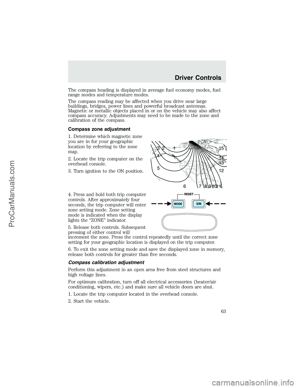
Compass zone adjustment
1. Determine which magnetic zone
you are in for your geographic
location by referring to the zone
map.
2. Locate the trip computer on the
overhead console.
3. Turn ignition to the ON position.
4.
Press and hold both trip computer
controls. After approximately four
seconds, the trip computer will enter
zone setting mode. Zone setting
mode is indicated when the display
lights the“ZONE”indicator.
5.Release both controls. Subsequent
pressing of either control will
increment the zone. Press the control repeatedly until the correct zone
setting for your geographic location is displayed on the trip computer.
6. To exit the zone setting mode and save the displayed zone in memory,
release both controls for greater than five seconds.
Compass calibration adjustment
Perform this adjustment in an open area free from steel structures and
high voltage lines.
For optimum calibration, turn off all electrical accessories (heater/air
conditioning, wipers, etc.) and make sure all vehicle doors are shut.
1. Locate the trip computer located in the overhead console.
2. Start the vehicle.
1 2 3
4
5
6 7 8 9 101112 13 14 15
Driver Controls
63
ProCarManuals.com